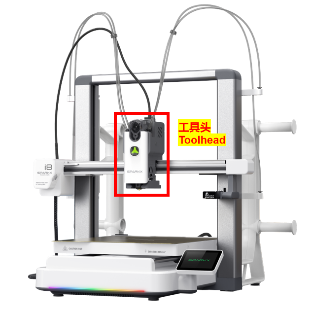
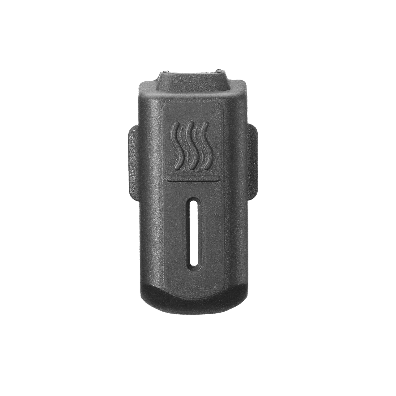
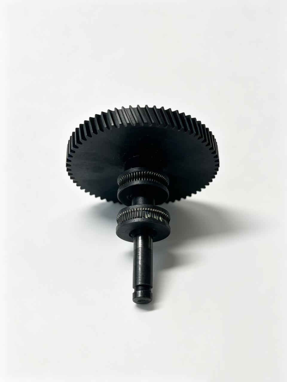
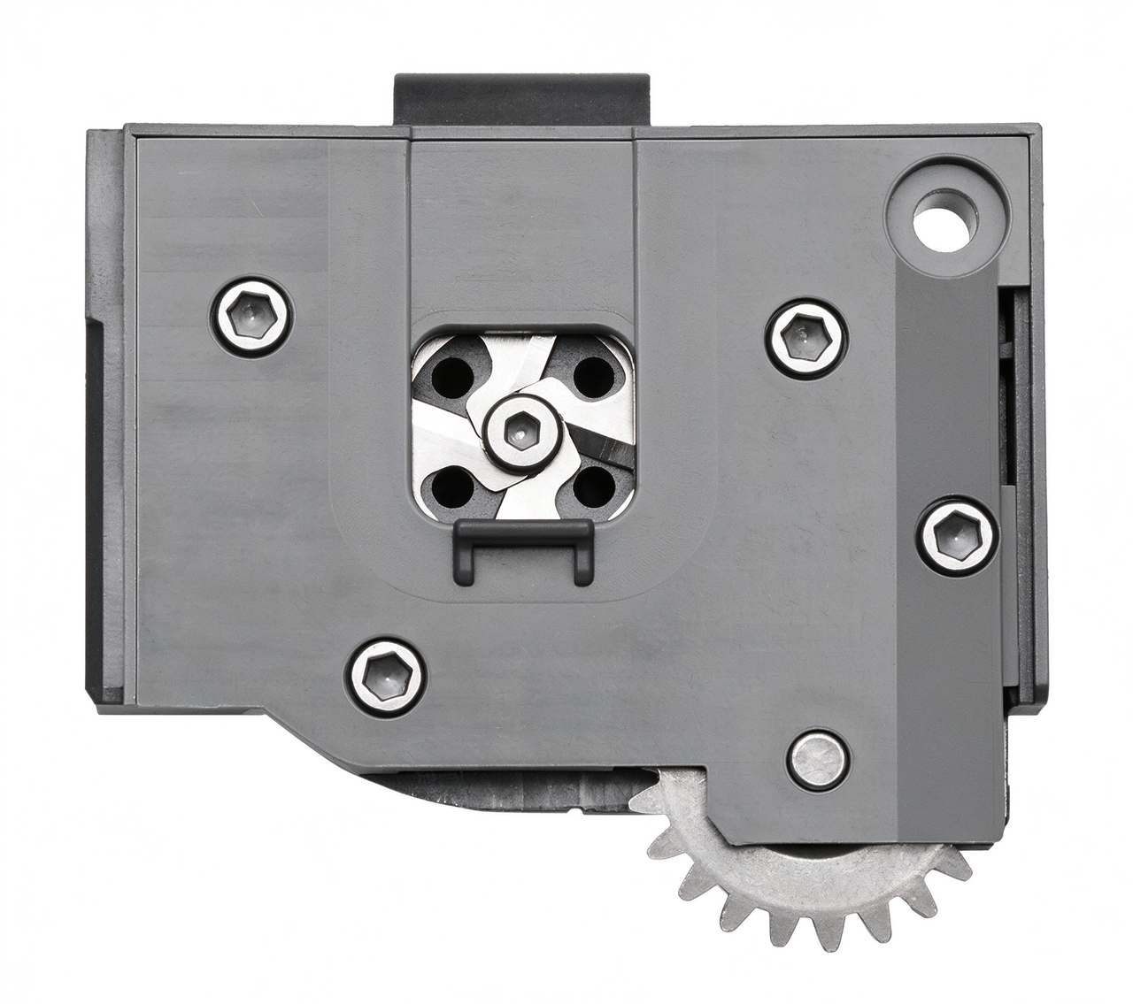
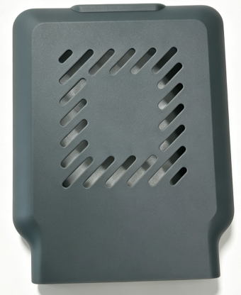
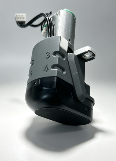
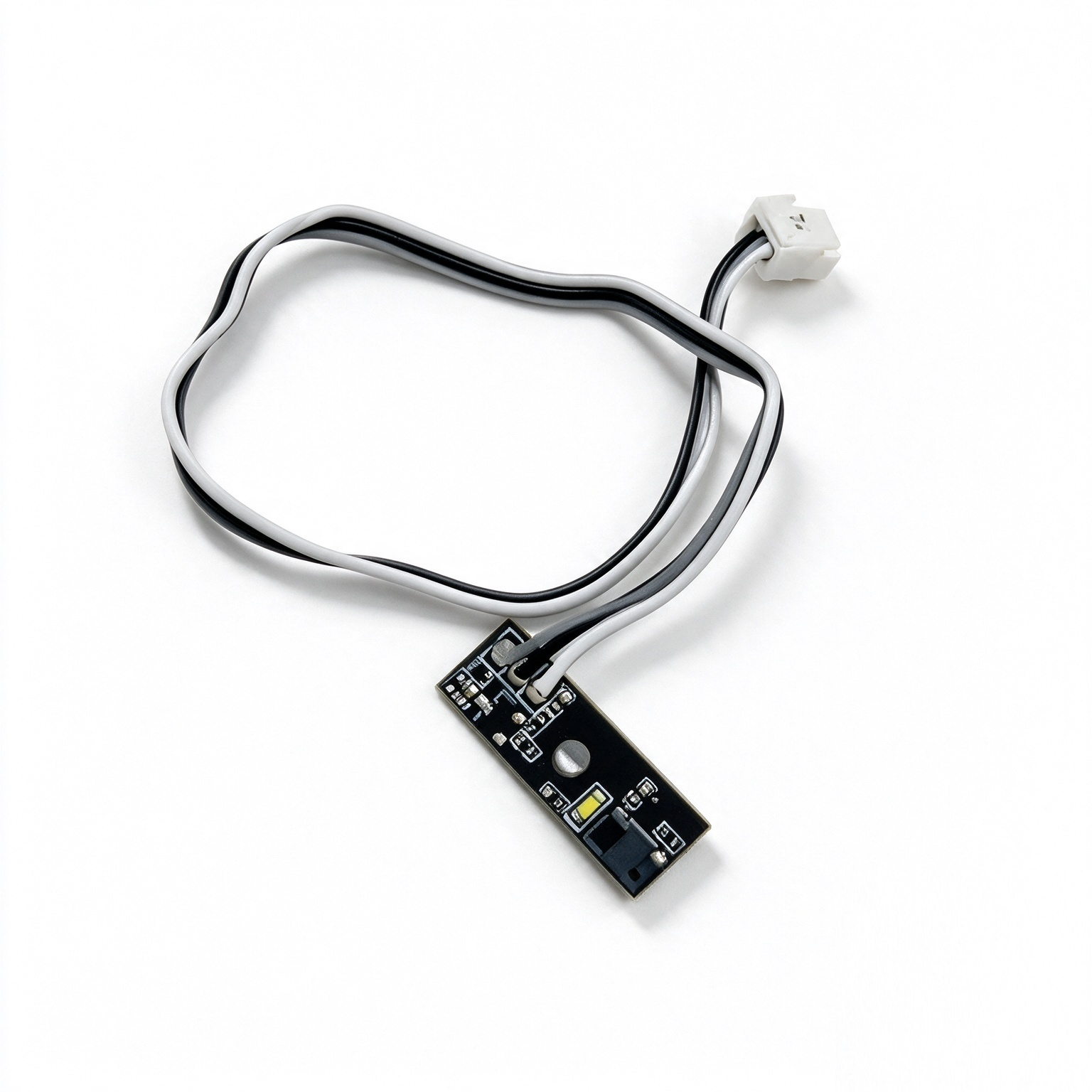
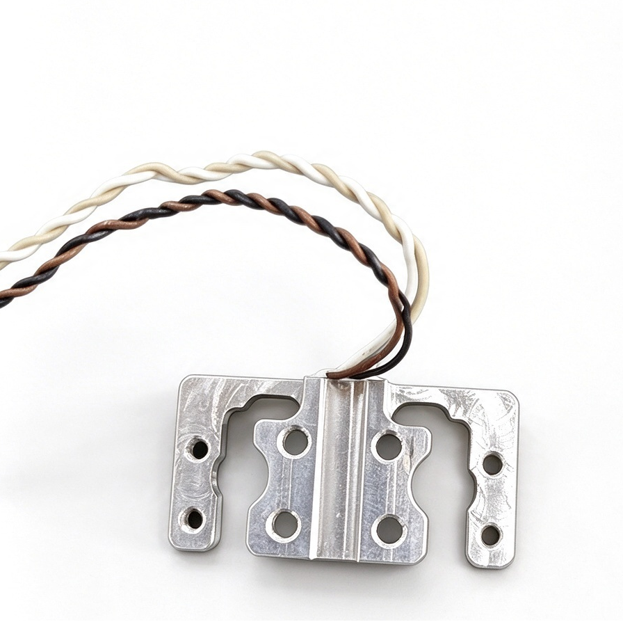
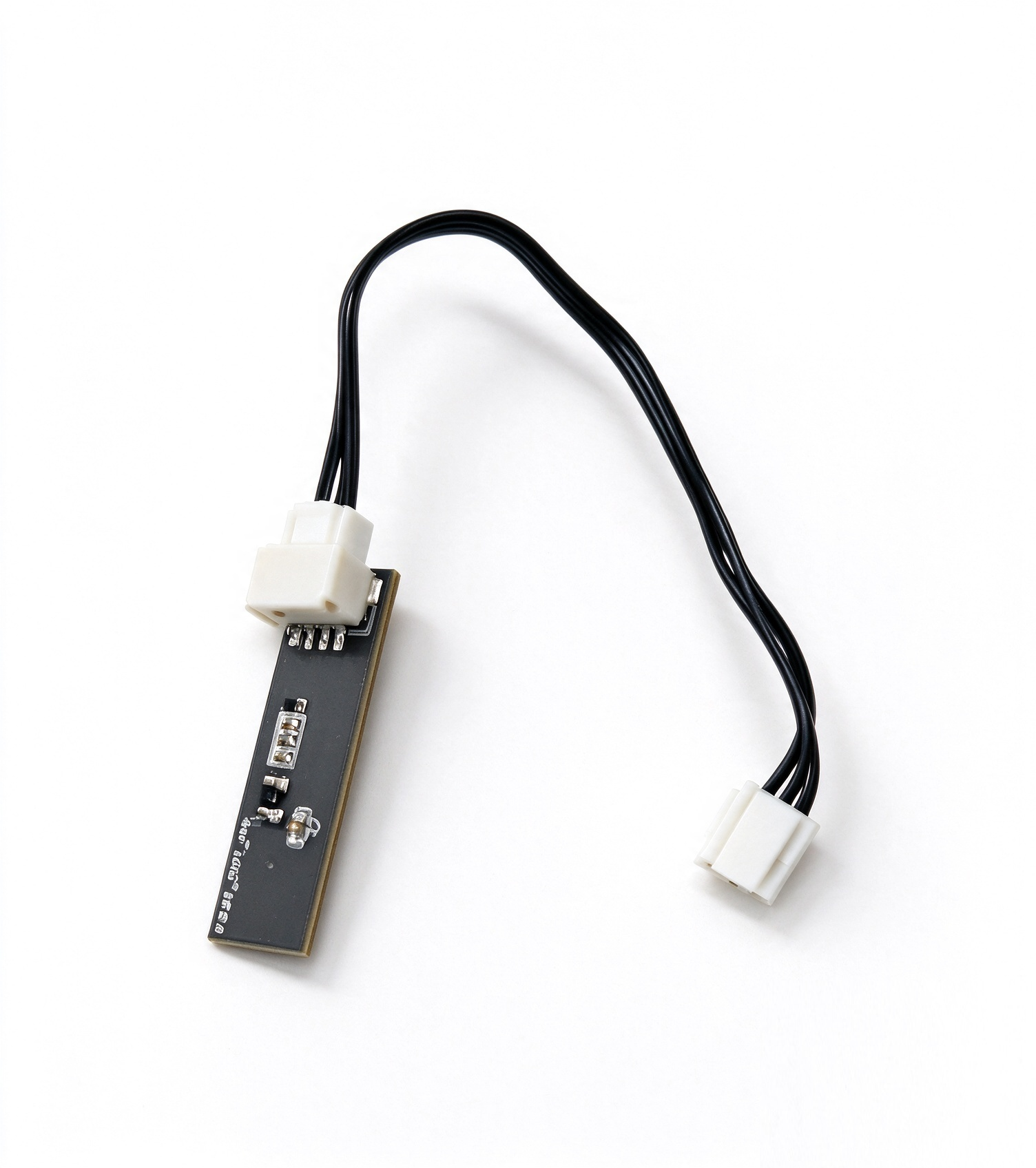
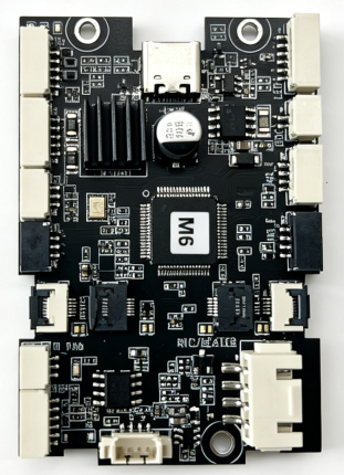
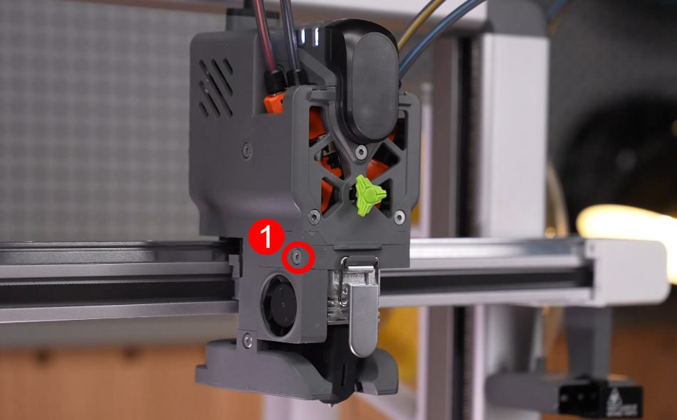
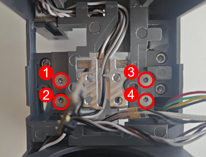
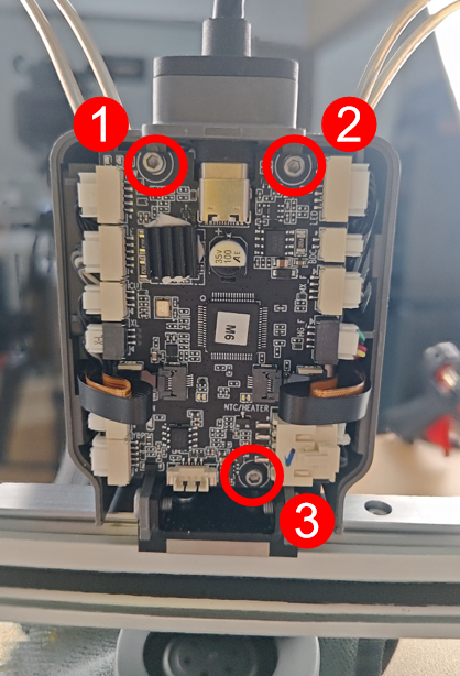
Note: Use a 1.5 mm hex key for the mounting screws of the Z-axis leveling sensor (extruder strain gauge). A 2.0 mm hex key is required for all other screws.
Before servicing the printer or its electronic components, including toolhead cables, turn off the printer and unplug the power cord to prevent short circuits, component damage, and other hazards.
Allow the hotend and heated bed to cool to room temperature before maintenance or troubleshooting. Do not handle hot components directly. If a separate, verified procedure requires working on hot components, wear heat-resistant gloves.
Complete the filament unloading and cutting procedure for all loaded channels on the current spool holder. See the Filament Loading and Unloading Guide for details.
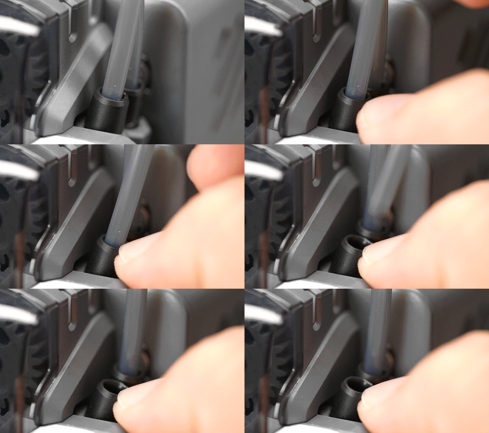
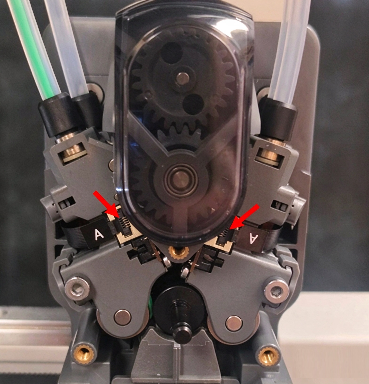
Press the release collar on the tube fitting and pull the PTFE tube upward to remove it.
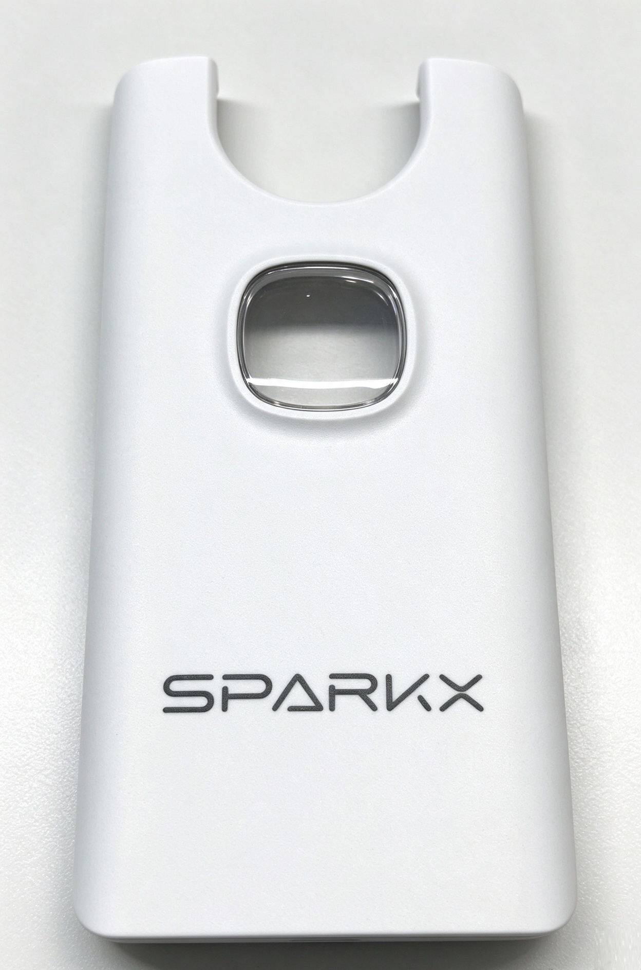
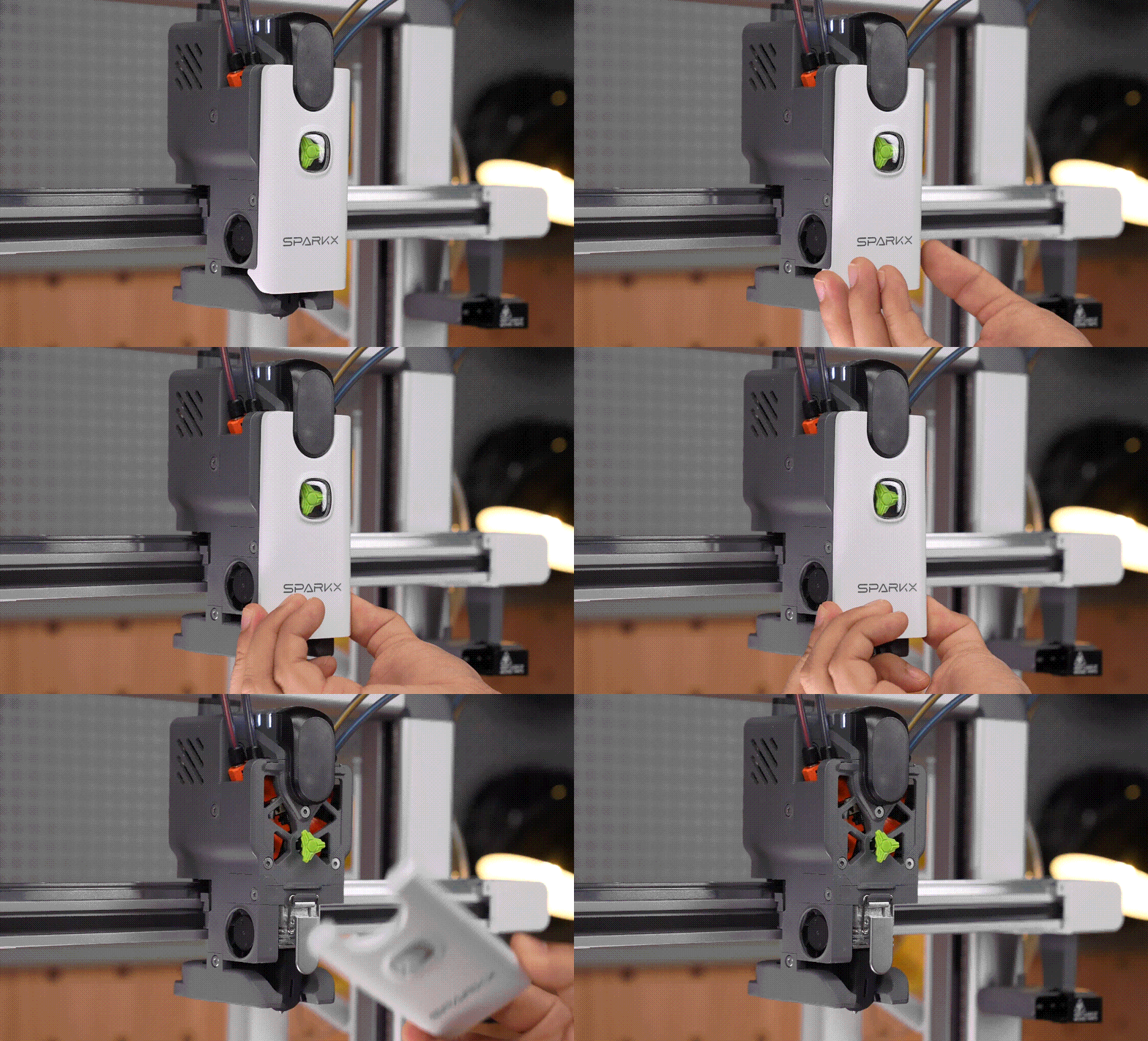
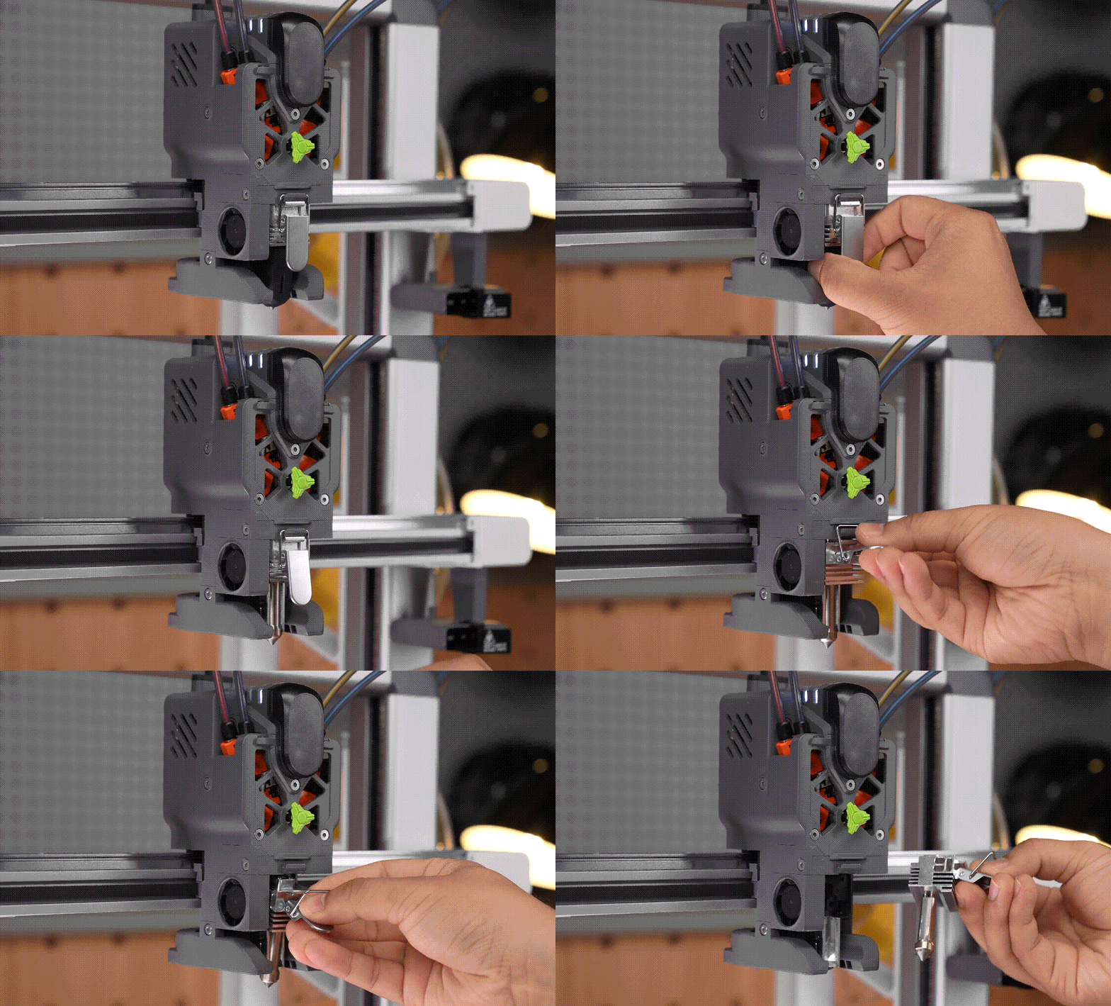
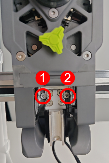
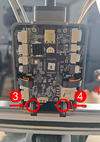
Press both sides of the toolhead front cover to release it, then remove the cover. Keep your fingers clear of the hotend cooling fans on either side. The release points are shown below.
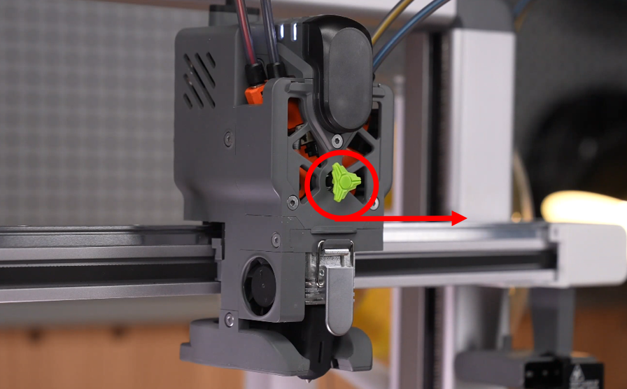
1. Grip the rotating wheel and pull it outward to remove it.
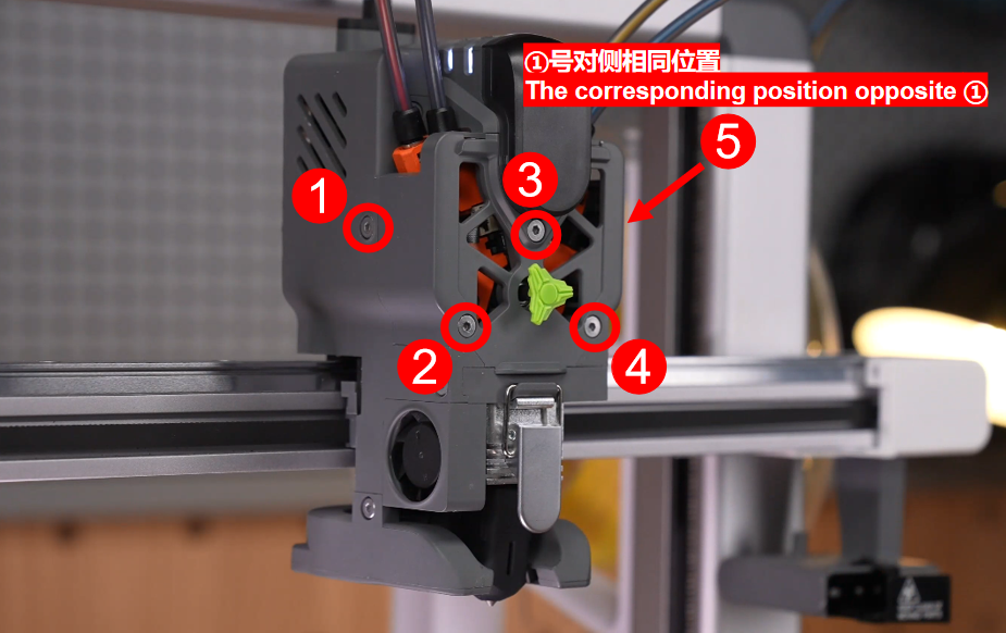
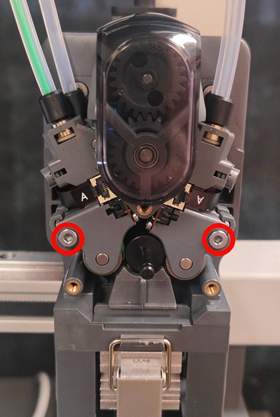
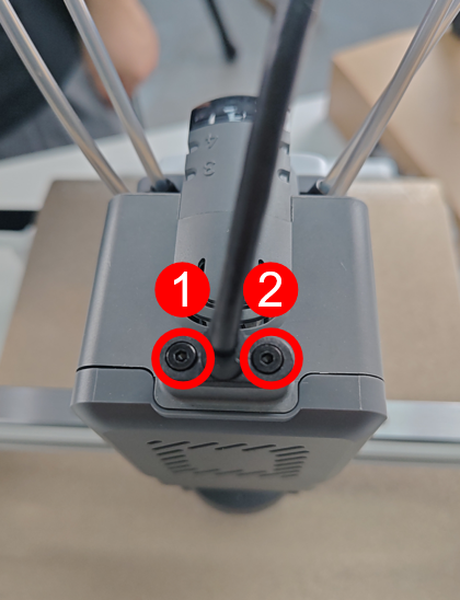
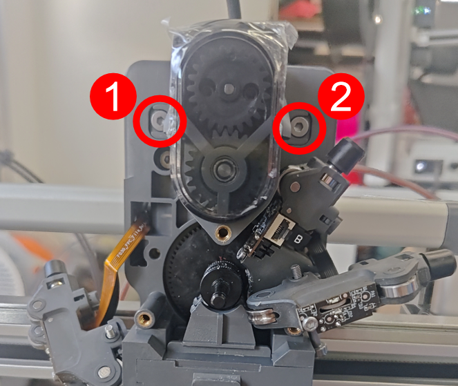
2. Use a 2.0 mm hex key to remove the five extruder cover screws: three at the front and two on the sides in total.
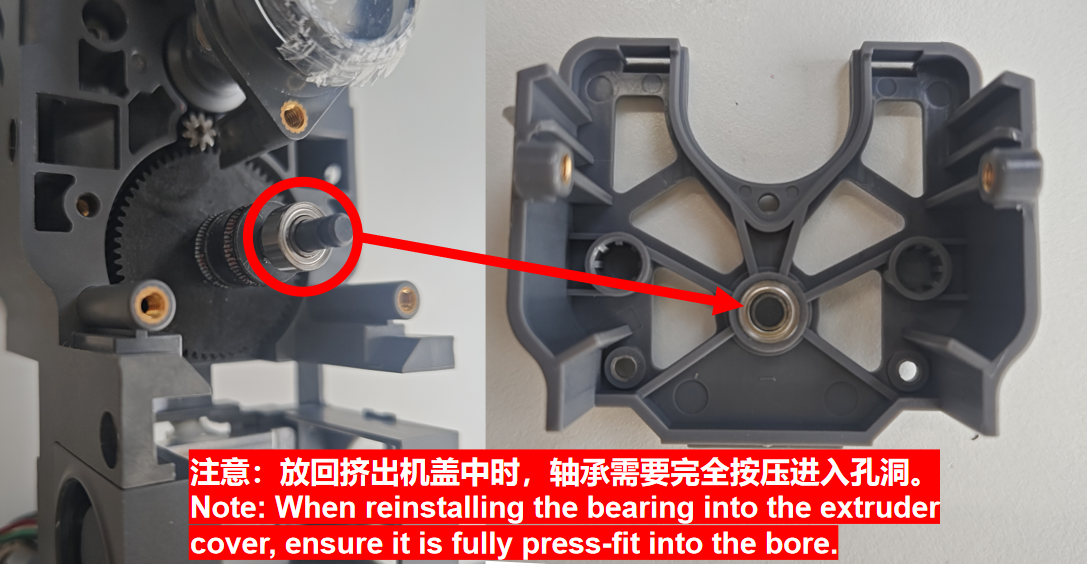
Note: When reinstalling the protective cover, if the bearing falls off and remains on the extruder gear shaft, fit the bearing into the bearing hole of the extruder protective cover as shown in the figure before installing the cover.
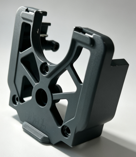
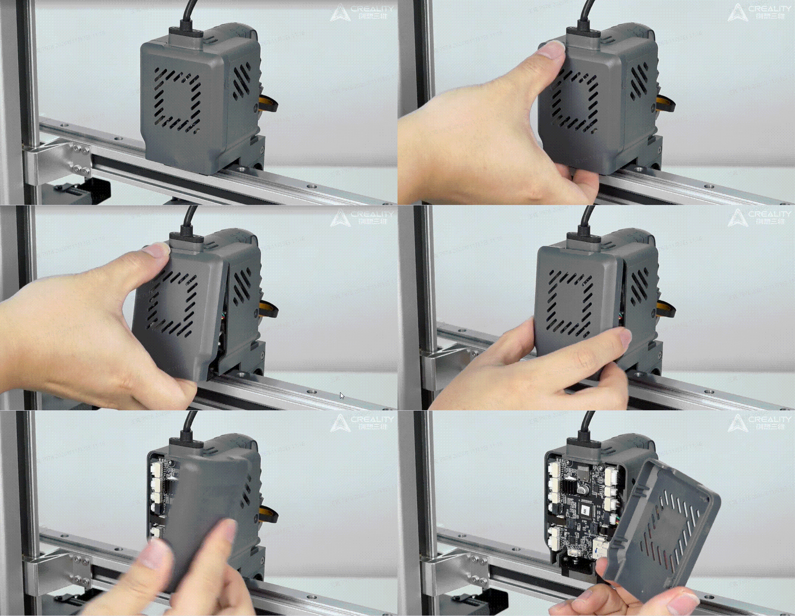
3. Grip both sides of the cover and pull it outward from the front of the toolhead, along the Y-axis, to remove it.
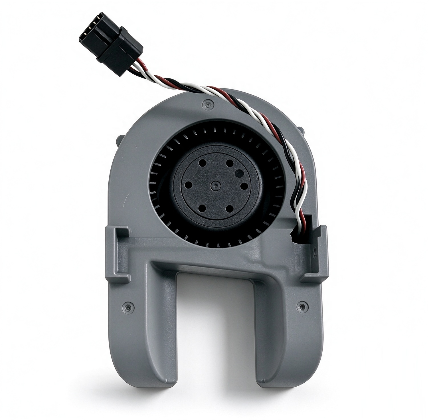
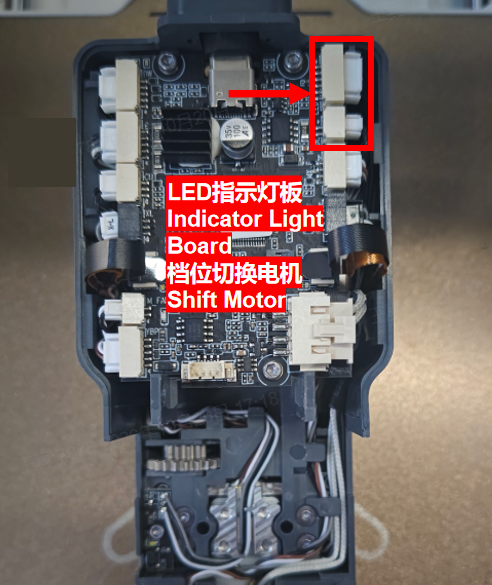
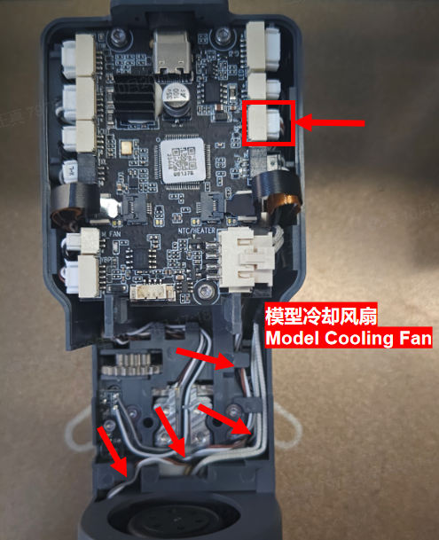
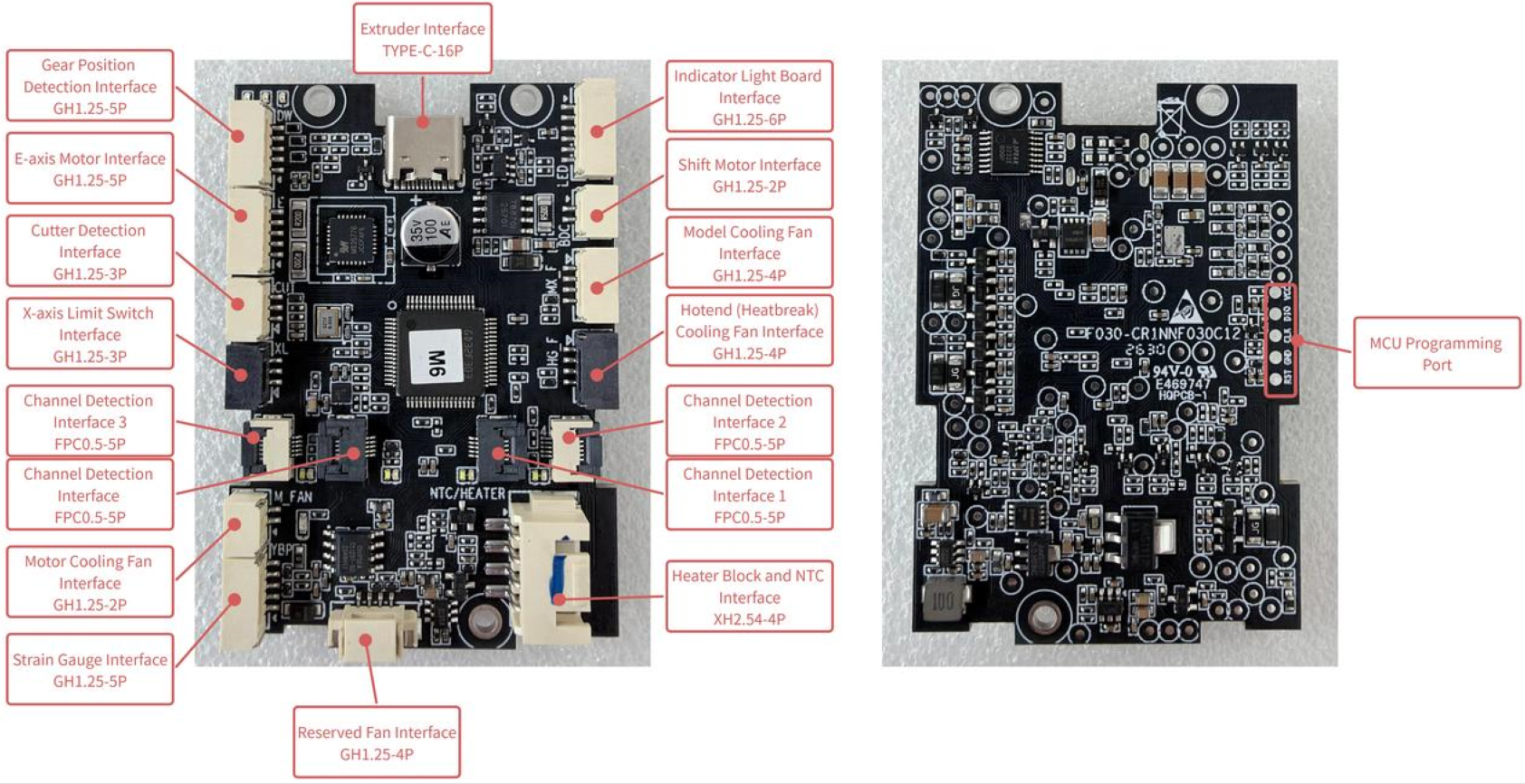
Press the latch on the fan cable connector at the toolhead control board, then pull the connector to the right to disconnect it.
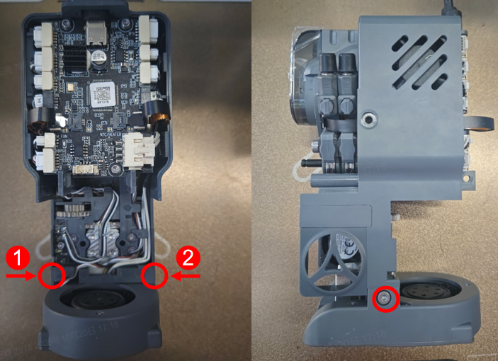
2. Use a 2.0 mm hex key to remove the two retaining screws on the left and right sides, then slide the fan assembly downward along the Z-axis to remove it.
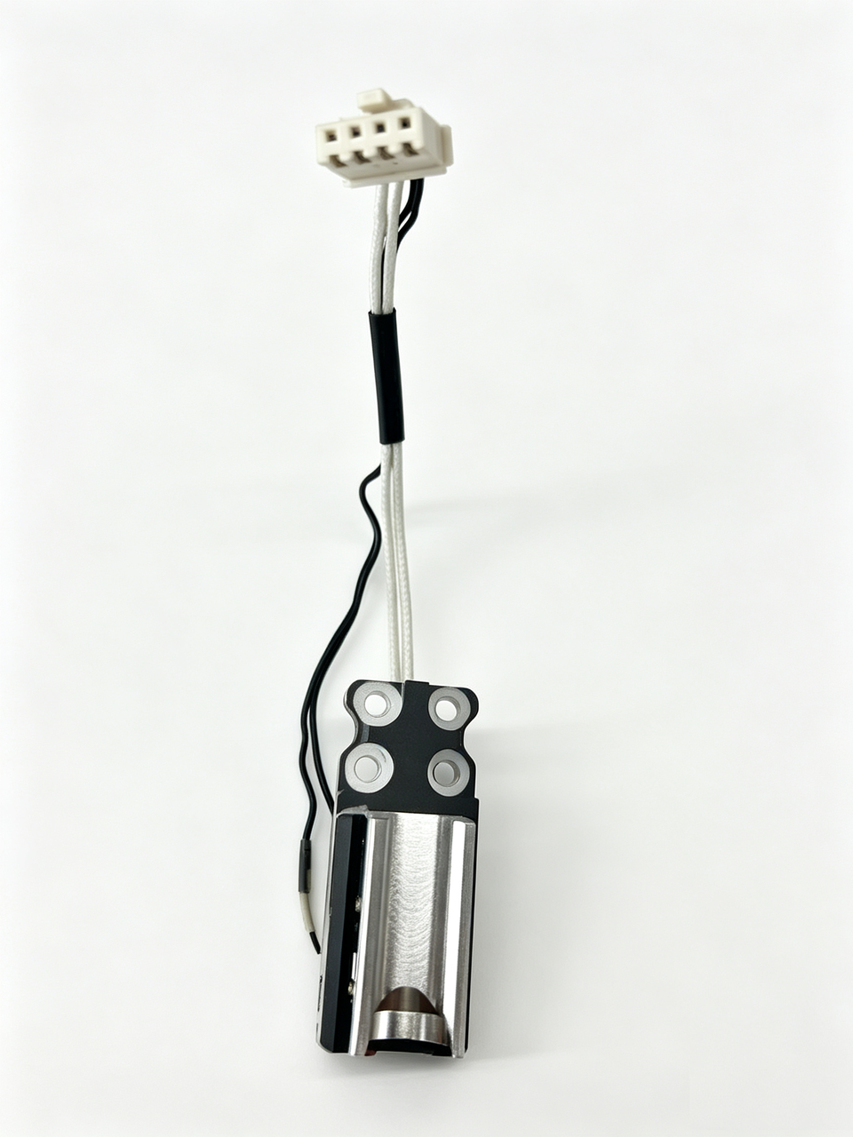
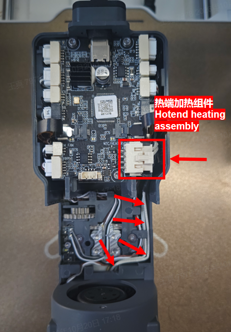
Press the latch on the TH mainboard and unplug the heating assembly terminal. Take the heating wire and thermistor wire out from the cable channel as shown below.
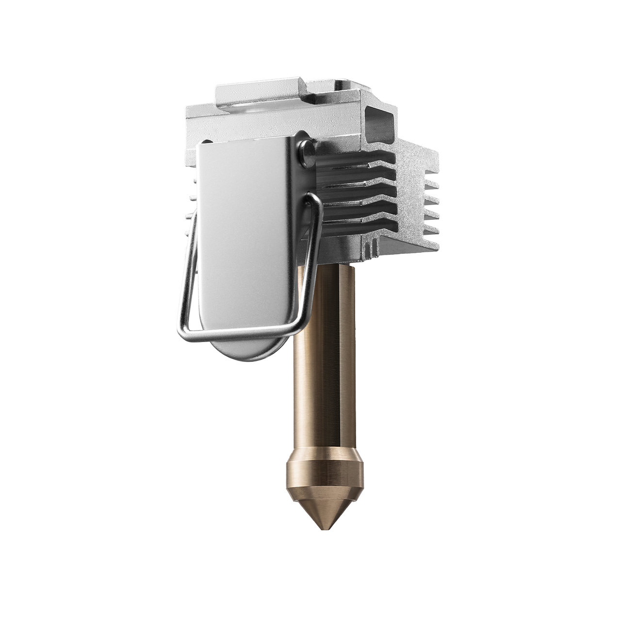
Use a 2.0 mm hex key to remove four retaining screws on the hotend heating module and remove the module.
Note: The part cooling fan must be removed or loosened prior to disassembling the heating assembly.
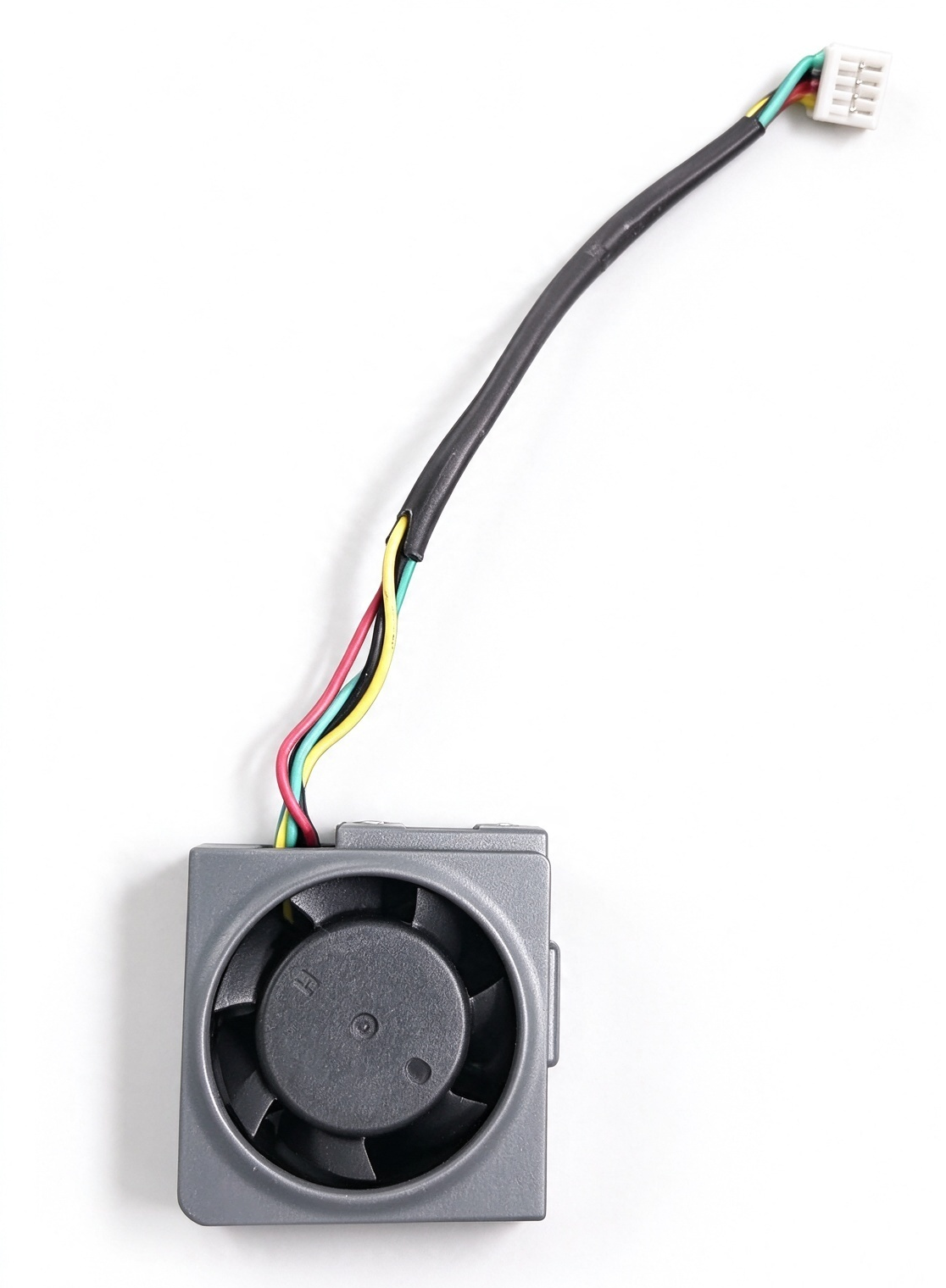
¶ 3.12 Remove the Hotend Heatsink Cooling Fan Assembly
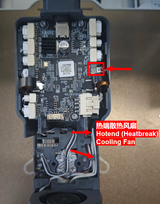
1. Press the latch and unplug the cooling fan terminal, then route the cooling fan wire out of the cable channel as shown in the figure below.
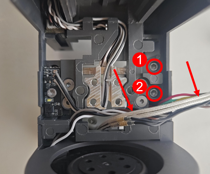
Note: Remove all flat cables from the right-side cable channel before disassembly. (Cable identification: Part cooling fan wire: white/black/brown/grey; Heating assembly wire: white/white/brown/brown; Hotend cooling fan wire: yellow/red/black/green)
2. After removing all flat cables, use a 2.0 mm hex key to remove the two retaining screws, then slide the hotend cooling fan assembly downward to take it out.
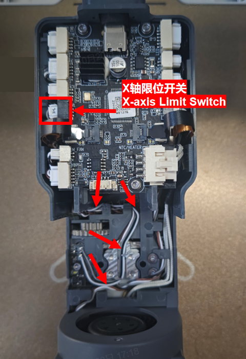
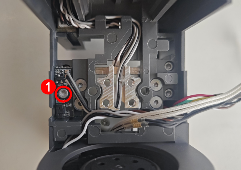
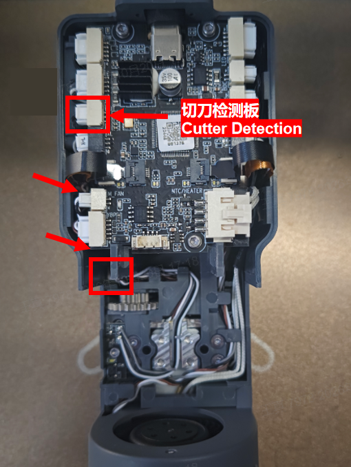
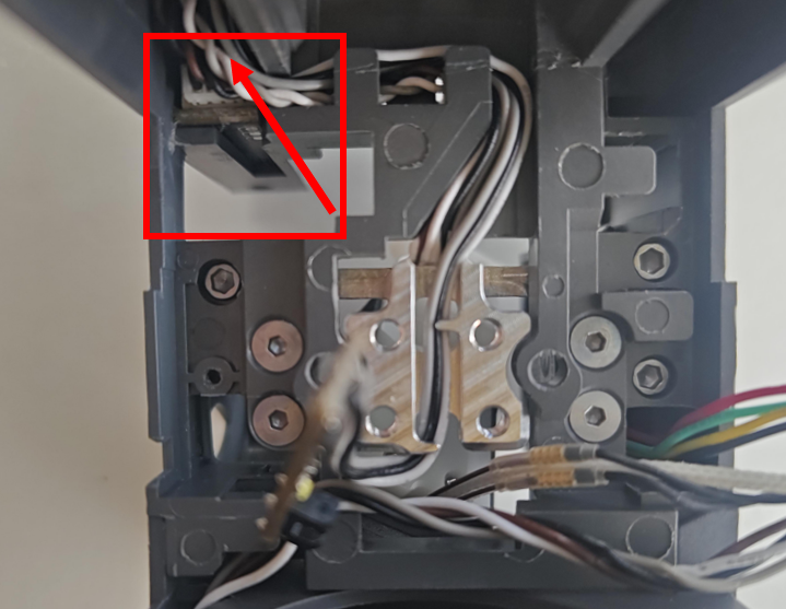
Press the latch and unplug the X-axis limit wire terminal. Use a 2.0 mm hex key to remove the single retaining screw of the limit switch, then pull out the flat cable.
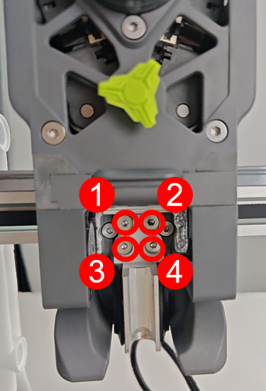
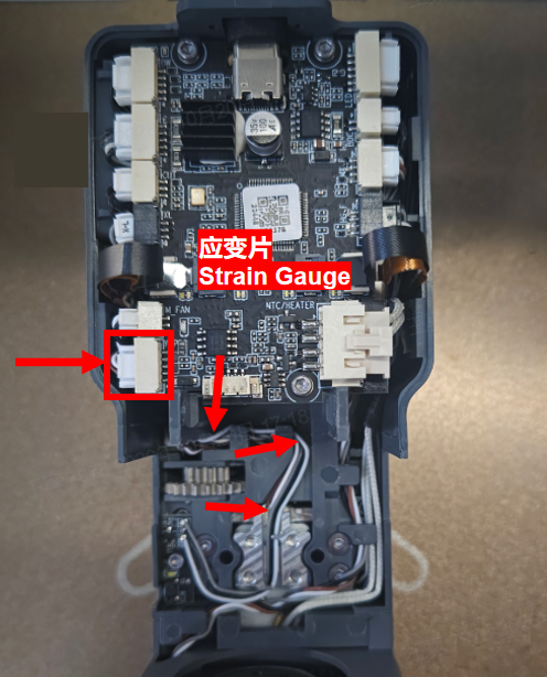
Press the latch and unplug the strain gauge terminal. Use a 1.5 mm hex key to remove the four retaining screws, then remove the strain gauge leveling sensor (Z-axis leveling sensor). The screws to be removed are shown below.