This guide explains how to replace the filament cutter assembly on the SPARKX i8.
¶ 1. i8 Cutter Assembly Overview
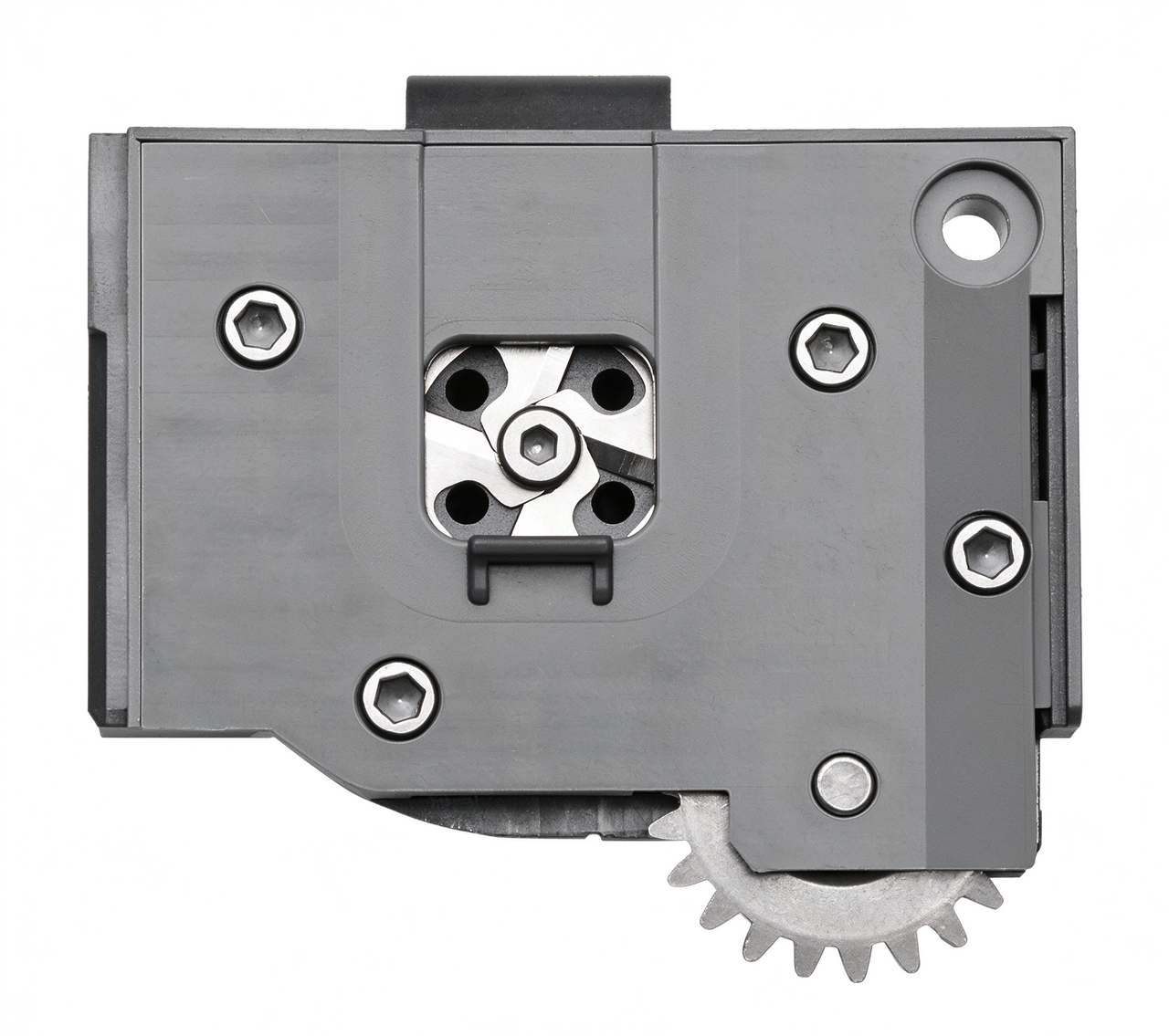
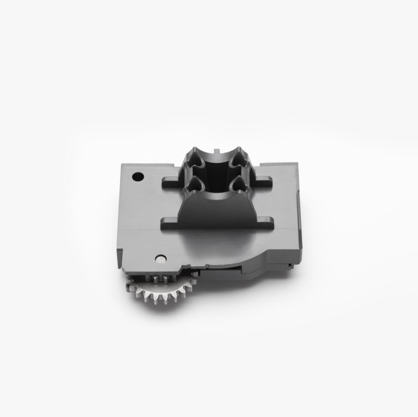
¶ 2. When to Replace the Assembly
Filament may clog the extruder cutter inlet during retraction. The cutting blade will gradually lose sharpness after prolonged cutting. It is recommended to replace the cutter assembly in advance if the following symptoms occur:
- Filament retraction is abnormal or the filament gets stuck during retraction
- The filament is not fully cut, leaving stringing residue at the cut
¶ 2.1 Tools Required
A replacement filament cutter assembly, or the original assembly after cleaning and inspection.
2.0 mm hex key.
¶ 3. Safety Precautions
IMPORTANT
- Before servicing the printer or its toolhead cables, turn off the printer and unplug the power cord to prevent short circuits, equipment damage, and electric shock.
- Allow the hotend and heated bed to cool to room temperature before maintenance or troubleshooting. Do not touch hot components with bare hands. If a separate procedure requires working on hot components, wear heat-resistant gloves to prevent burns.
- If you have questions about this operation guide, please submit a ticket on the Creality Cloud App. We will offer technical support promptly.
¶ 4. Remove the Old Parts
¶ 4.1 Preliminary Tasks
¶ 4.1.1 Unload Filament and Remove the PTFE Tubes
- Complete the filament unloading and cutting procedure for all loaded channels on the current spool holder. See the Filament Loading and Unloading Guide for details.
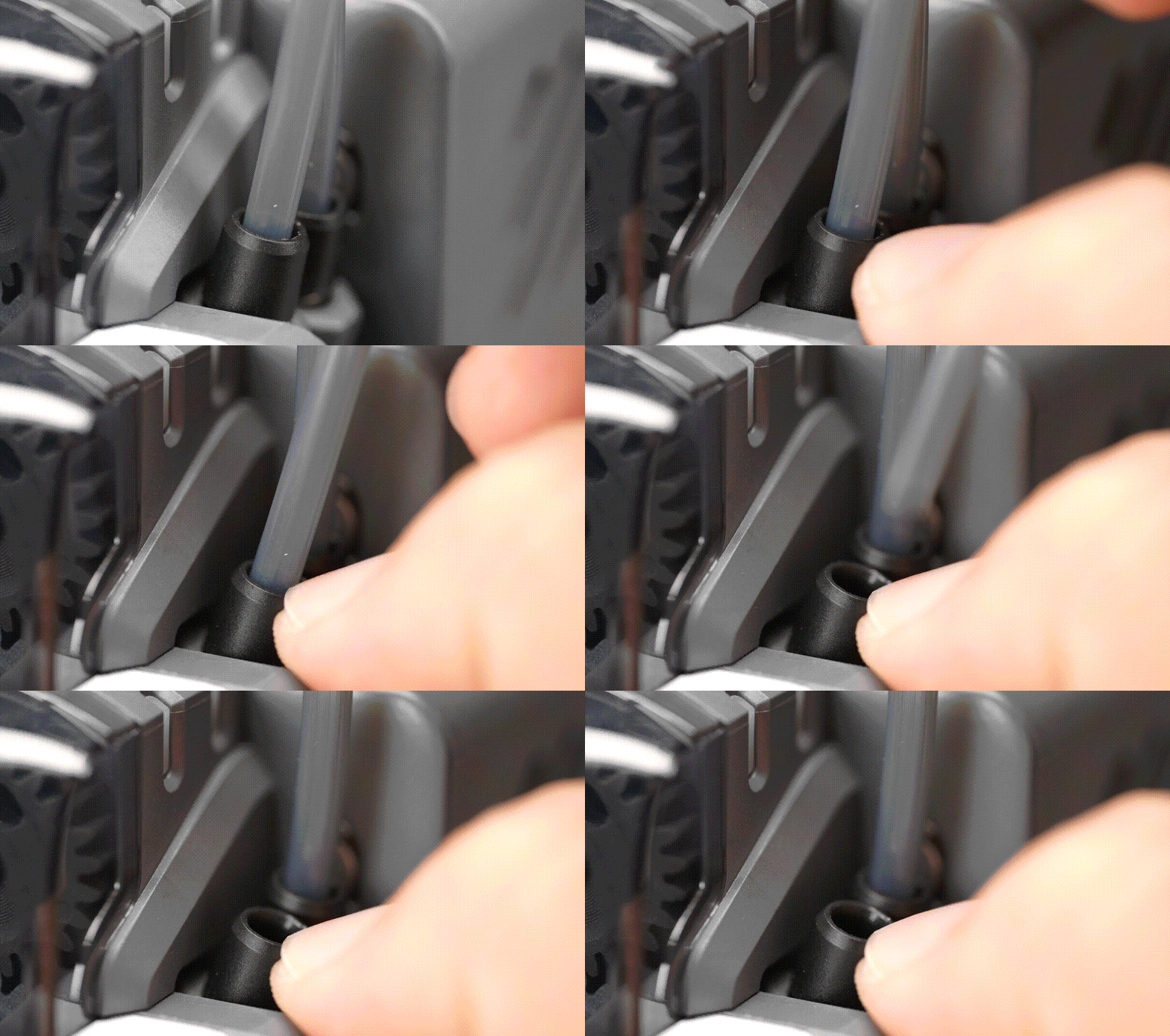
- Press the release collar on the tube fitting and pull the PTFE tube upward to remove it.

¶ 4.1.2 Remove the Toolhead Front Cover
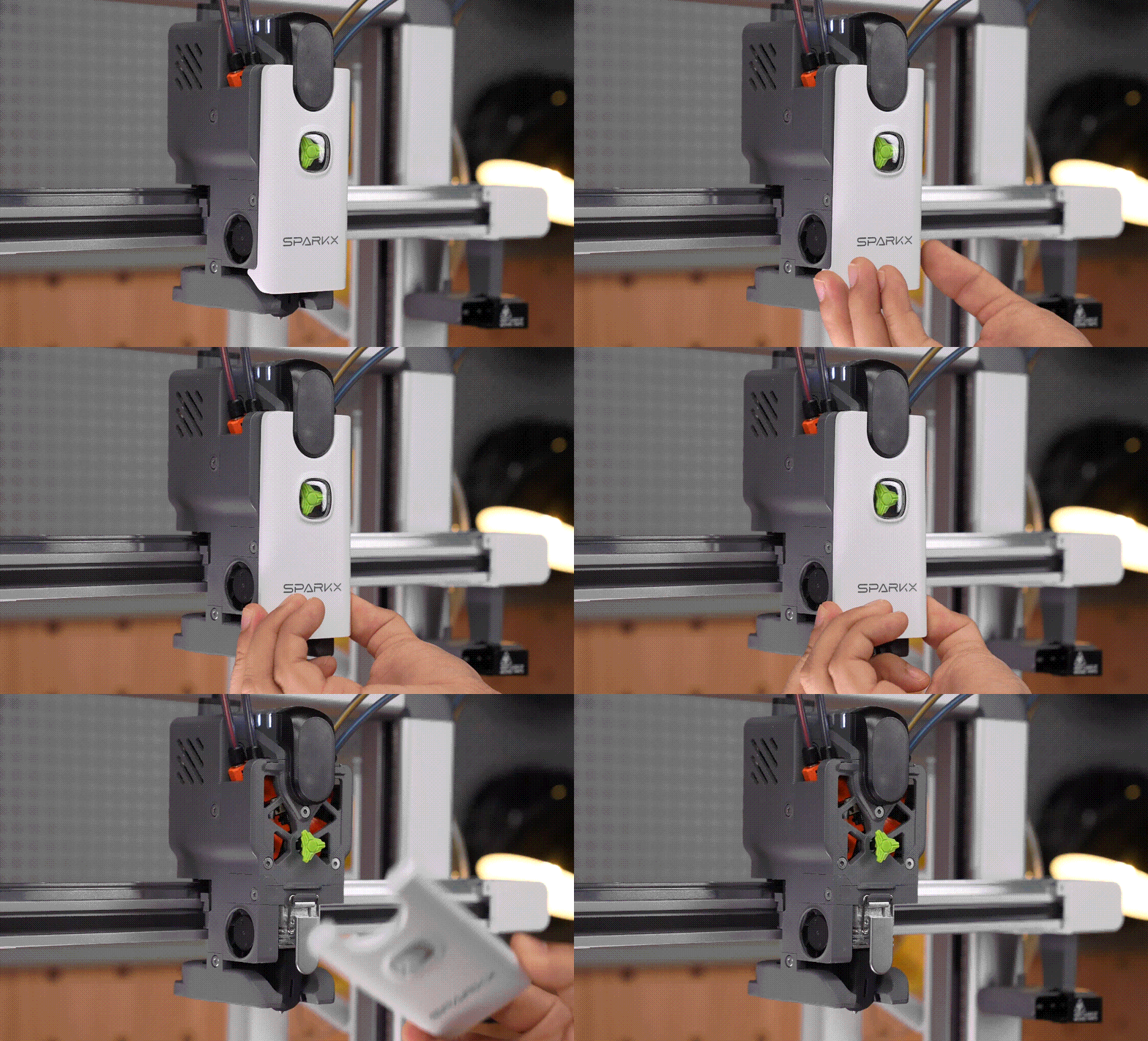
Press both sides of the toolhead front cover to release it, then remove the cover. Keep your fingers clear of the hotend cooling fans on either side. The release points are shown below.
¶ 4.1.3 Remove the Extruder Cover
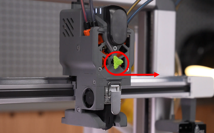
1. Grip the rotating wheel and pull it outward to remove it.
2. Use a 2.0 mm hex key to remove the five extruder cover screws: three at the front and two on the sides in total.
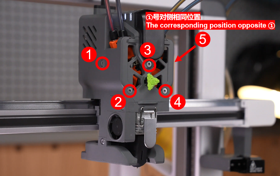
3. Grip both sides of the cover and pull it outward from the front of the toolhead, along the Y-axis, to remove it.
¶ 4.2 Remove the Hotend
1. Remove the hotend silicone sock.
2. Check for filament residue that has melted and solidified around the nozzle.
If residue is present, heat the hotend to 230 °C. Use a cardboard piece, or grip an alcohol-moistened kitchen paper towel with pliers to gently wipe off surface filament residue.
3. Release the hotend retaining clip and push it upward to open a gap between the hotend and the cutter assembly.
4. Pull the hotend straight down to remove it.

¶ 4.3 Loosen Filament Feed Channel Screws
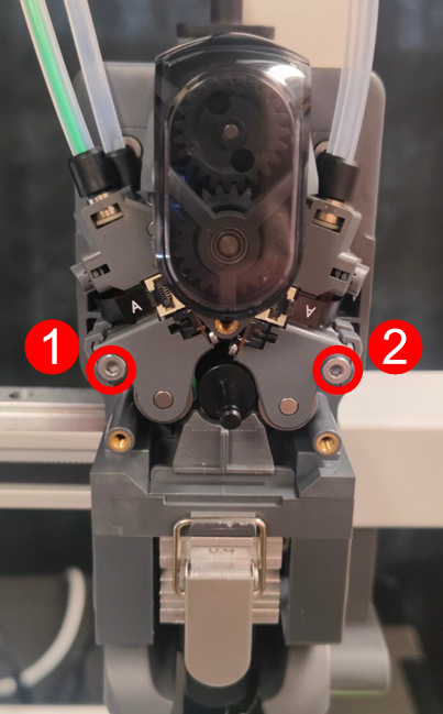
Use a 2.0 mm hex key to remove the two retaining screws for the left and right filament feed channel assemblies. Release the latches, disconnect the FPC cables, and remove the left and right filament feed channel assemblies. The screws to be removed are shown in the figure below.
Note: You may also only loosen the screws instead of removing the assemblies; rest the feed channels temporarily on the edge of the extruder bracket.
¶ 4.4 Remove the Filament Cutter Assembly
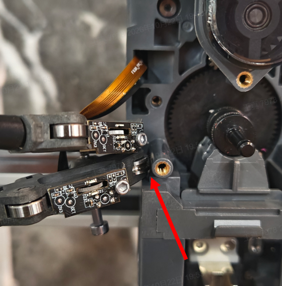
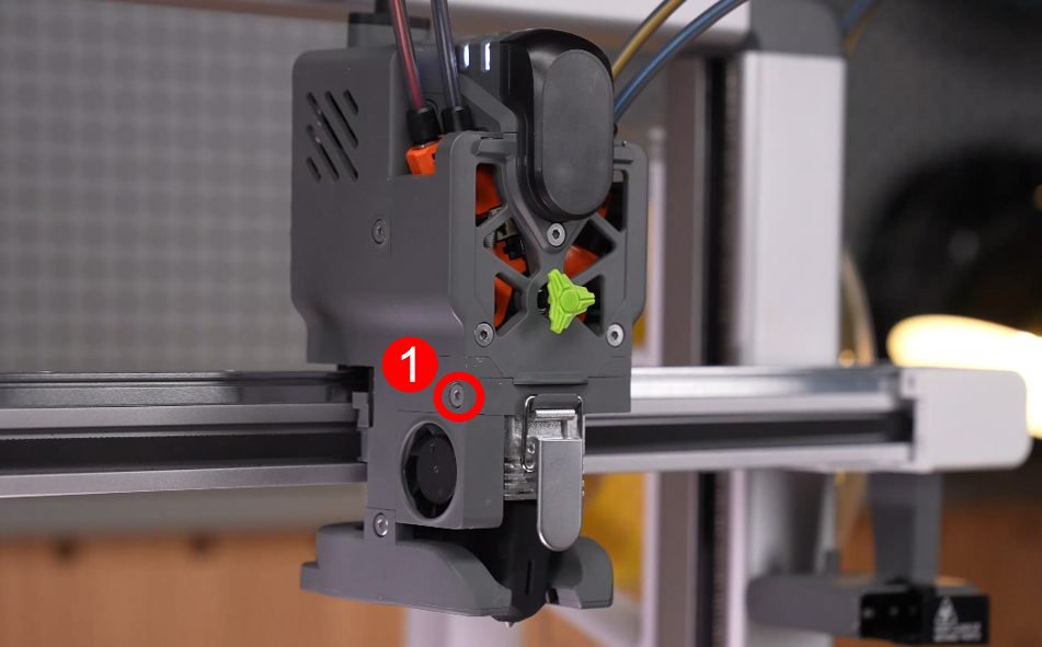
1. Use a 2.0 mm hex key to loosen and remove the retaining screw.
2. Insert one finger deep into the cutter channel and pull gently outwards to slide the entire assembly out of the mounting slot.
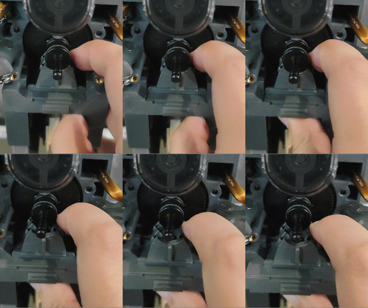
Alternative: Use a screwdriver to assist with pulling out the cutter assembly.
¶ 4.5 Remove and Clean the Extruder Gear
Note: Before reinstalling the cutter assembly, it is recommended to clean the extruder gear and idler gear. Small filament debris may accumulate on the gears after prolonged use, and cleaning ensures smooth operation going forward.
- After removing the cutter assembly, you may take out the extruder gear.
- Use a soft brush together with air blowing to clear plastic powder from the gear gaps and ensure no foreign matter is trapped between the teeth.
- Wipe the gears with a lint-free cloth lightly dampened with alcohol.
¶ 5. Install the Assembly
¶ 5.1 Reinstall the Extruder Gear
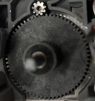
Place the extruder gear back in its slot in the correct orientation. Make sure it meshes correctly with the extruder motor gear above it.
¶ 5.2 Install the Filament Cutter Assembly
1. Push the cutter rack fully behind the cutter gear inside the toolhead until it fits against the X-axis guide rail.
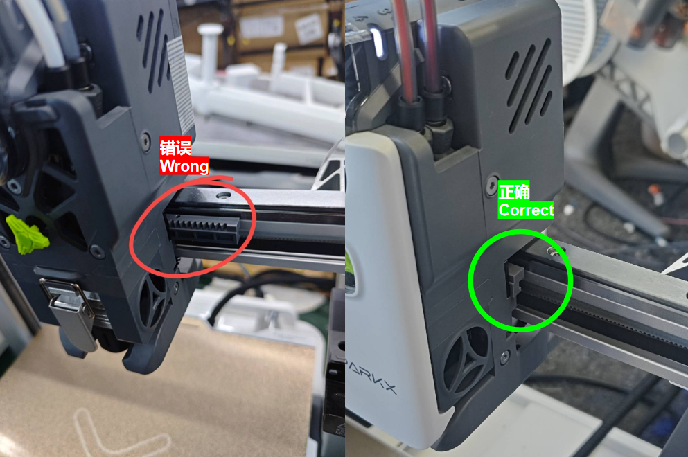
2. Make sure all four cutting edges of the cutter are fully exposed. If misaligned, manually rotate the cutter gear to reset it.
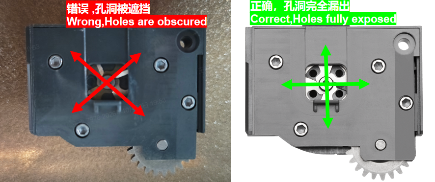
Tip: The reset is successful when you feel the gear snap into magnetic engagement.
3. Align the cutter assembly with the mounting slot and push it in smoothly until seated.
4. Tighten the retaining screw with moderate torque. Do not over-tighten to avoid thread stripping.
Note: When reinstalling the cutter assembly, refer to the figure to ensure that the cutter gear and rack are in their reset positions.
¶ 5.3 Reassemble the Toolhead
¶ 1. Reinstall the Filament Feed Channel Assemblies
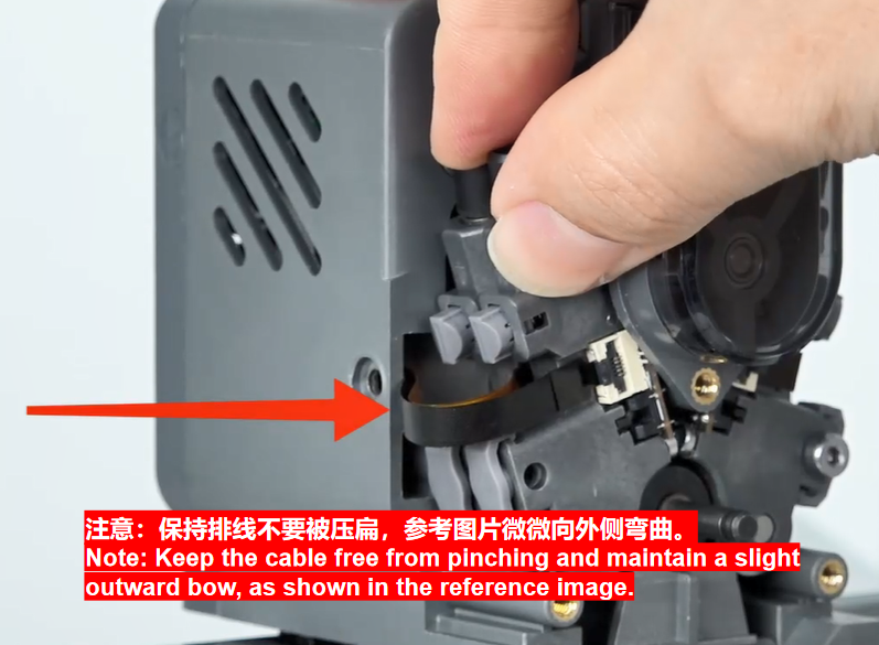
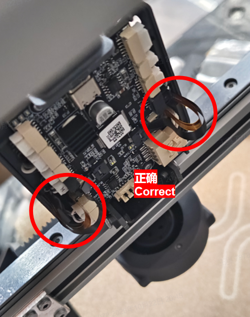
Return the left and right filament feed channel assemblies to their original positions and reinstall the mounting screws. Make sure the FPC cables are not pinched or strained. If their routing needs adjustment, remove the toolhead rear cover and gently reposition the cables along their original paths. Check that they are clear of pinch points before reinstalling the cover.
¶ 2. Reinstall the Extruder Cover
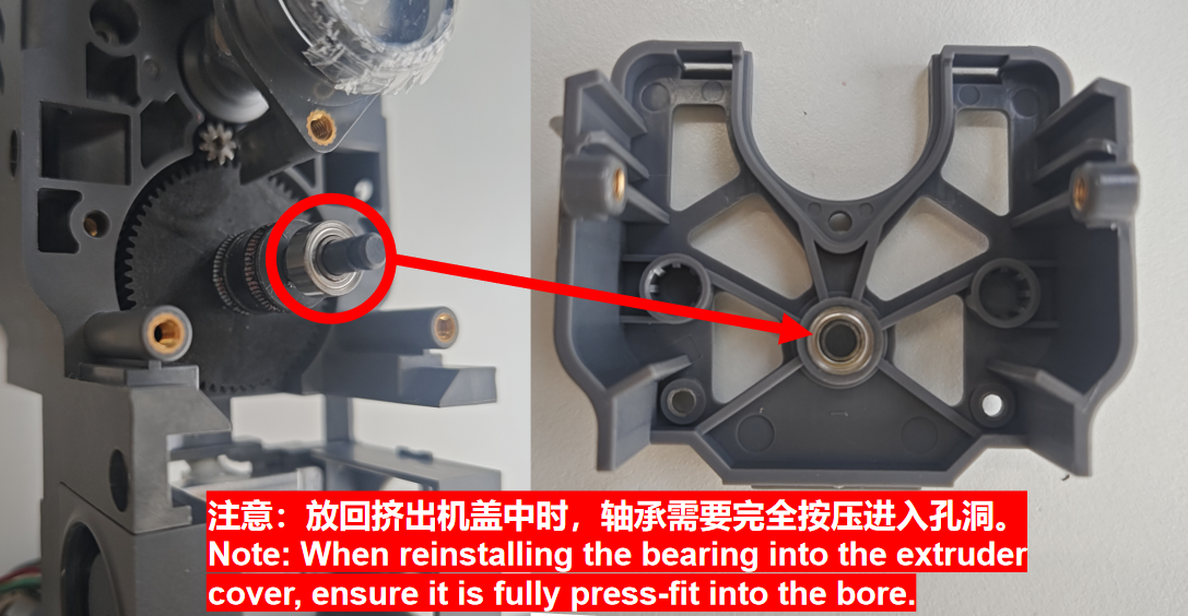
Align the locating pins and reinstall the extruder cover. Reinstall and tighten the five mounting screws, then refit the rotating wheel.
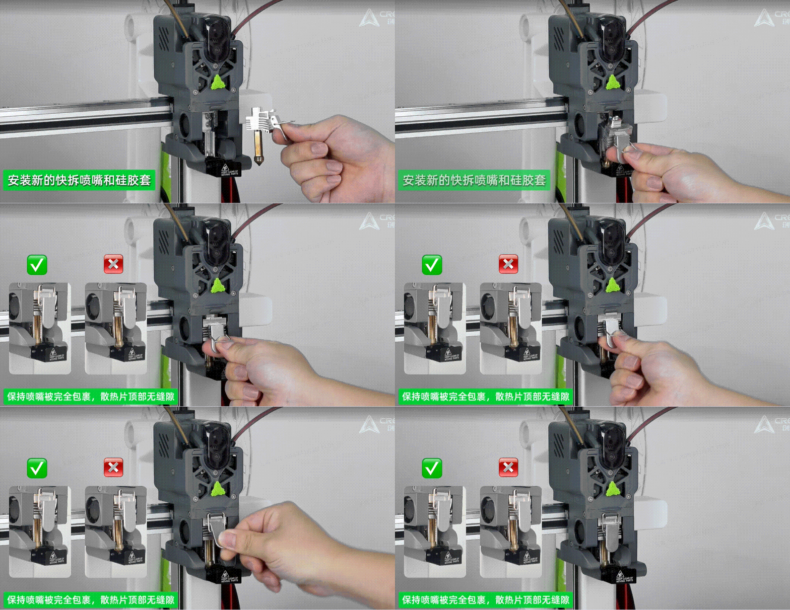
¶ 3. Reinstall the Hotend and Silicone Sock
Reinstall the hotend following the i8 Hotend and Sock Replacement Guide. Check that its filament inlet aligns with the cutter opening and that the metal spring clip is securely locked, then refit the silicone sock.
¶ 4. Reinstall the Front and Rear Covers
Make sure the rear cover is correctly installed and secure. Align the clips at the top of the front cover and gently press the cover into place until they engage. Check that the cover is secure.
¶ 5. Reconnect the PTFE Tubes
Reconnect each PTFE tube to its original toolhead inlet. Push it fully into the fitting, then gently pull back to check that it is secure.
¶ 5.4 Check the Installation
Once all removed parts have been reinstalled and all cables and PTFE tubes are correctly connected, reconnect the power cord and turn on the printer.
- On the machine screen, tap Help > Maintenance > Calibration > Cutter Calibration to run the calibration procedure.
- Run a filament loading and unloading test. Check that the filament feeds and unloads smoothly and is cut completely.
- Print a small test model. Check that filament feeds normally and that there is no gear slipping or unusual noise.