¶ Operation Video
The replacement procedure is relatively complex. We strongly recommend watching the full video guide or reviewing this Wiki before proceeding.
Since the Hotend Heating Assembly and the Part Cooling Fan Assembly are related, this guide can be used as a reference for replacing both components.
Replace i7 Hotend heating assembly & part cooling fan
¶ i7 Part Cooling Fan Assembly
¶ Required Tools
H2.0 Hex wrench
Tweezers
¶ Safety Preparation
Turn off the power and unplug the Power cable
Before operation, ensure the Hotend and Heated Bed have completely cooled down to avoid burns
¶ Replacement Procedure
For easier operation, it is recommended to remove the Toolhead Assembly first. The following steps are based on removing the Toolhead Assembly.
¶ Remove the Toolhead Assembly
Remove the PTFE tube from the Toolhead Manifold. Press down the Pneumatic Fitting to release and pull out the tube
Remove the Toolhead front cover, then remove the Hotend Sock, and take out the Quick-Release Hotend Do not operate at high temperature to avoid burns
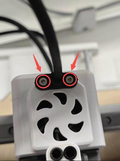
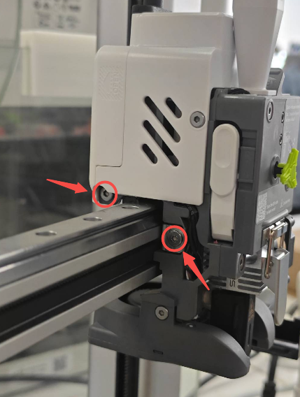
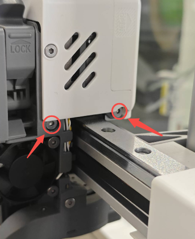
Unscrew the two screws on the top of the Toolhead, then disconnect the Toolhead Data Cable
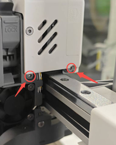
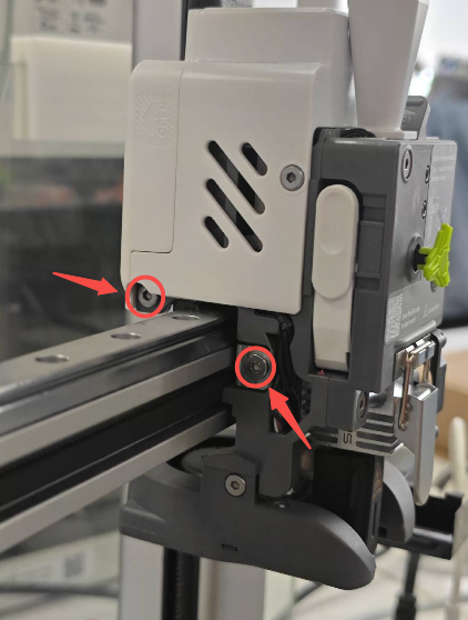
Unscrew the four screws on both sides of the Toolhead, then remove the entire Toolhead Assembly
 |
 |
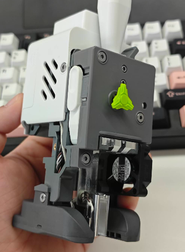 |
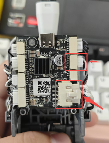
Remove the Toolhead Back Cover to expose the Toolhead Board, then unplug the connector of the Extruder Cooling Fan
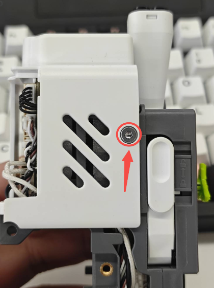
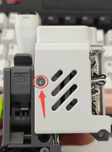
Use an H2.0 Hex wrench to remove the two screws on both sides of the rear housing, then lift off the Toolhead Back Cover
 |
 |
¶ Remove the Hotend Heating Assembly and Part Cooling Fan
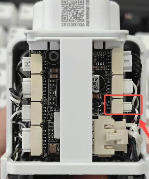
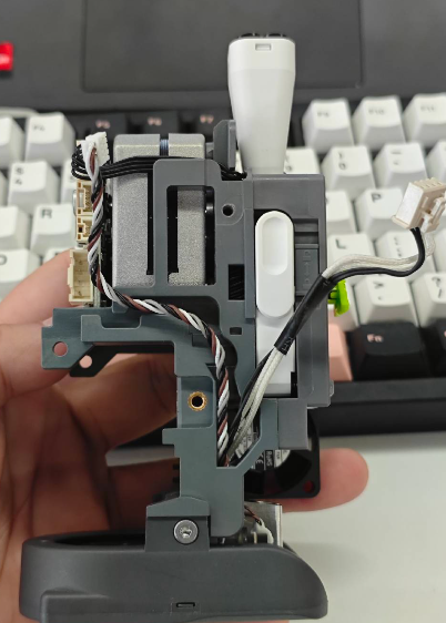
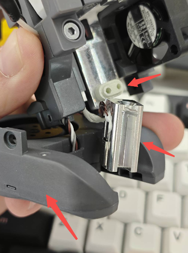
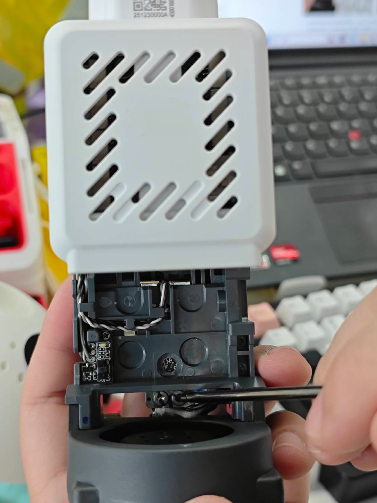
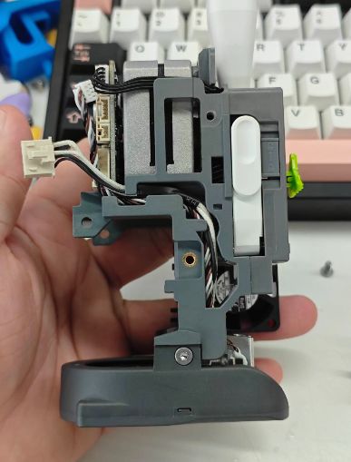
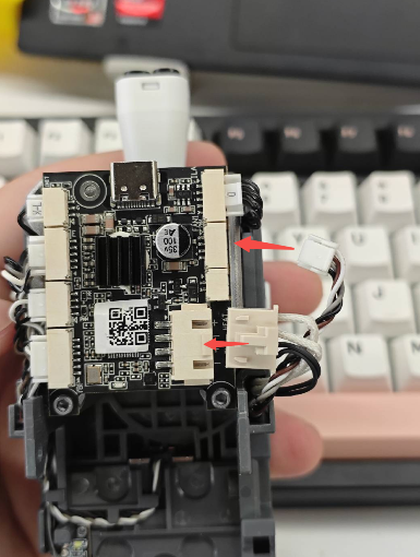
As shown, unplug the connectors of the Part Cooling Fan Assembly and the Hotend Heating Assembly, then carefully remove the wires from the cable slot
 |
 |
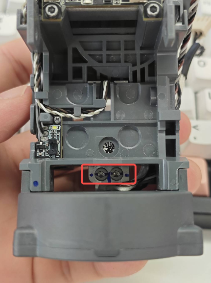
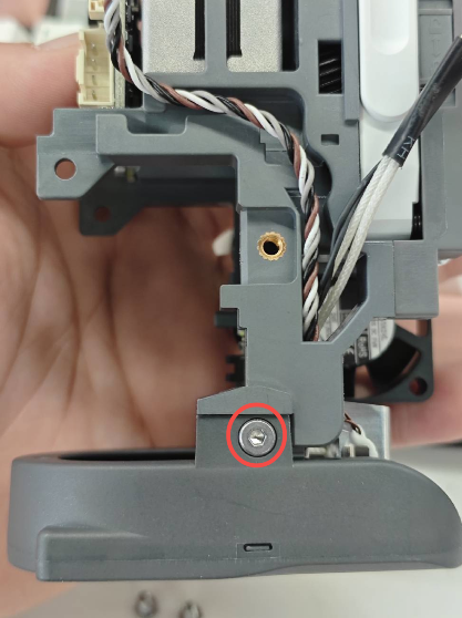
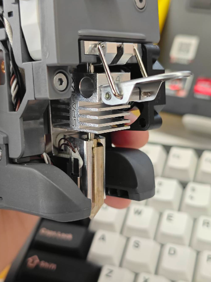
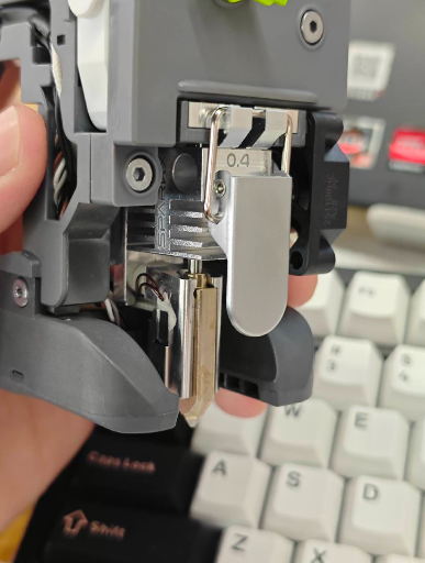
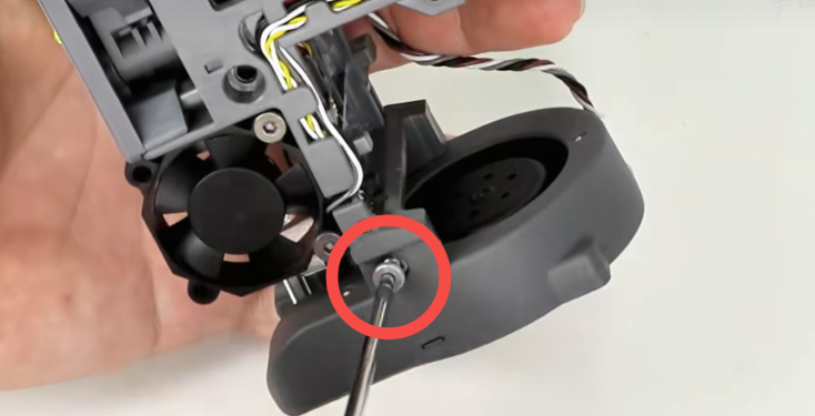
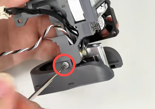
Unscrew the two screws on the back of the Hotend Heating Assembly to loosen it; Unscrew the two screws on both sides of the Part Cooling Fan Assembly to loosen it
 |
 |
 |
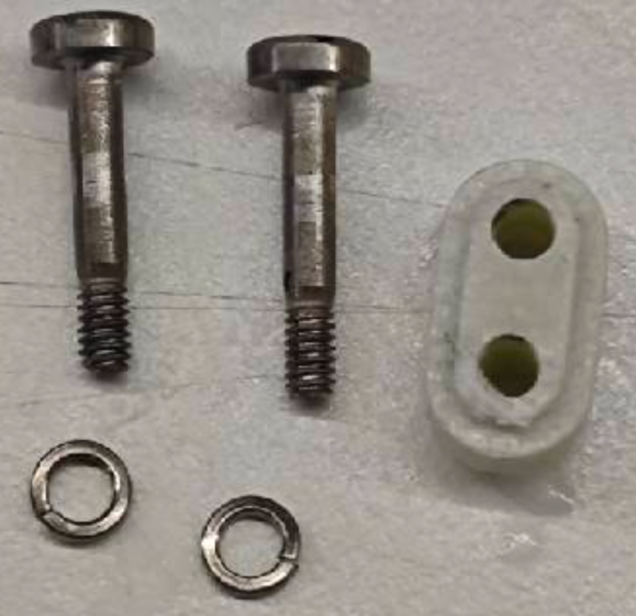
After loosening both components, remove the Hotend Heating Assembly more easily Do not forget the insulation block and screw washers of the heating assembly
¶ Install the New Part Cooling Fan
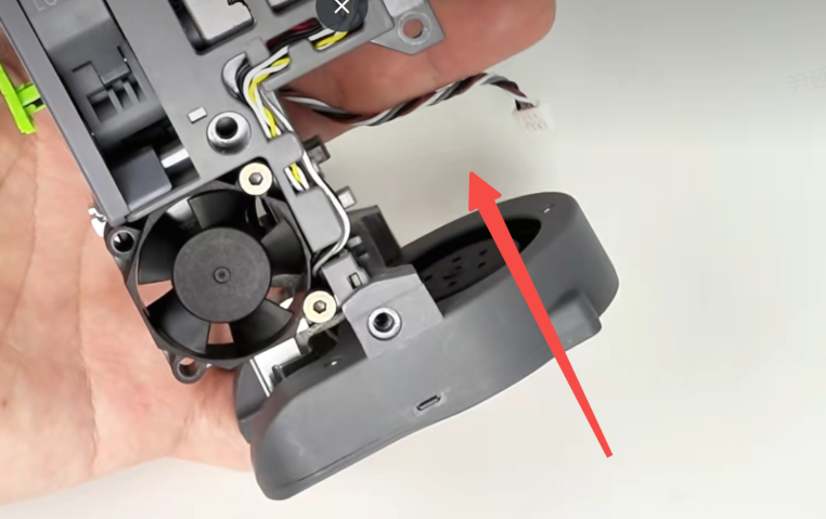
Route the cable of the new Part Cooling Fan Assembly back through the side hole and organize the wiring
Install the Hotend Heating Assembly, routing its cable through the side opening; organize the cables separately and ensure the insulation block is installed
Secure the Part Cooling Fan Assembly and the Hotend Heating Assembly with screws Do not fully tighten the heating assembly screws at this stage
Install the Quick-Release Hotend back onto the Toolhead and lock it in place, then fully tighten the two screws of the Hotend Heating Assembly
 |
 |
 |
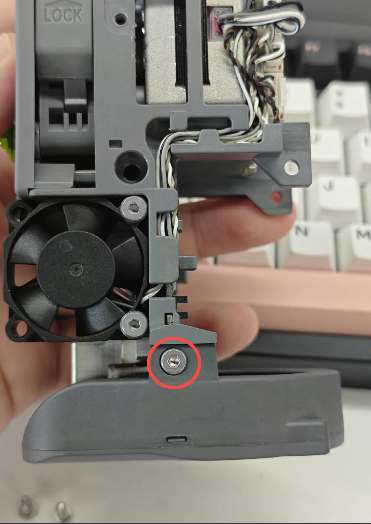
Install the fan back to its position and tighten the two fixing screws.
 |
 |
 |
Arrange all cables into the cable slot and connect them to the corresponding ports on the Toolhead Board
 |
 |
Reinstall the Toolhead Back Cover, reconnect the Extruder Cooling Fan, and secure the housing with screws
¶ Reinstall the Toolhead Assembly
Reinstall the Toolhead Assembly onto the i7 X-axis Assembly and secure it with screws.
 |
 |
Reinstall the Hotend Sock and the Toolhead front cover to complete the replacement
After replacement, it is recommended to perform Auto Calibration to ensure optimal performance: SPARKX i7 Automatic Calibration Guide