¶ Video Guide
The replacement procedure is relatively complex. We strongly recommend watching the full video guide or carefully reviewing this Wiki before proceeding. As the Heating Assembly and the Part Cooling Fan Assembly are related, the replacement of both components can be carried out by referring to this video guide.
Replace i7 Hotend heating assembly & part cooling fan
¶ Hotend Heating Assembly
The Hotend Heating Assembly is the component that heats the hotend. It transfers heat to the hotend through direct contact, melting the filament, which is then extruded by the extruder.
In this guide, we will explain how to replace the Hotend Heating Assembly for the i7 series.
¶ When to Replace
The Hotend Heating Assembly is malfunctioning.
The Heating Assembly is damaged or its thermal insulation degrades quickly.
Replacement is recommended by Creality after-sales support.
¶ Required Tools
- H2.0 hexagonal wrench
- Tweezers
¶ Safety Precautions
Turn off the power and unplug the power cord.
Before starting, check the temperatures of the hotend and heated bed. Avoid operating while they are hot to prevent burns from accidental contact.
¶ Procedure
For easier handling, it is recommended to remove the toolhead before replacing the Heating Assembly. The replacement will follow the steps for disassembling the toolhead.
¶ Removing the Toolhead
Remove the PTFE tube from the Filament Hub by gently pressing down the connector and pulling out the tube.
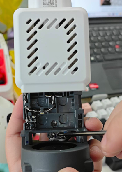
Remove the toolhead front cover, then remove the hotend sock and the quick-release hotend. Be careful not to operate while hot to avoid burns.
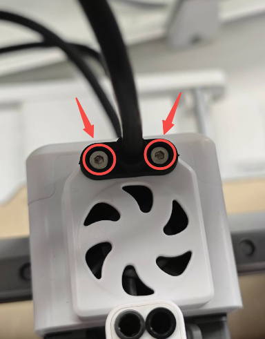
Unscrew the two screws on top of the toolhead and disconnect the toolhead cable.
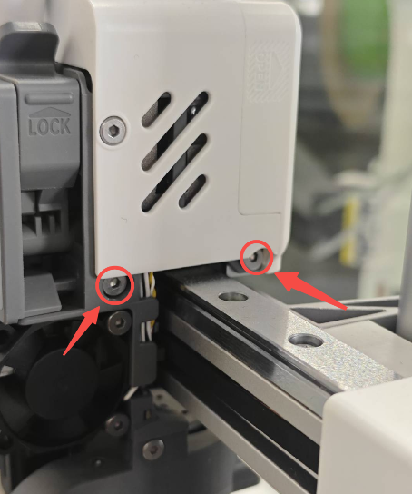
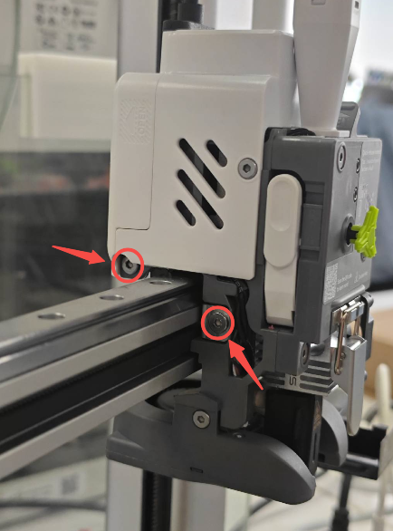
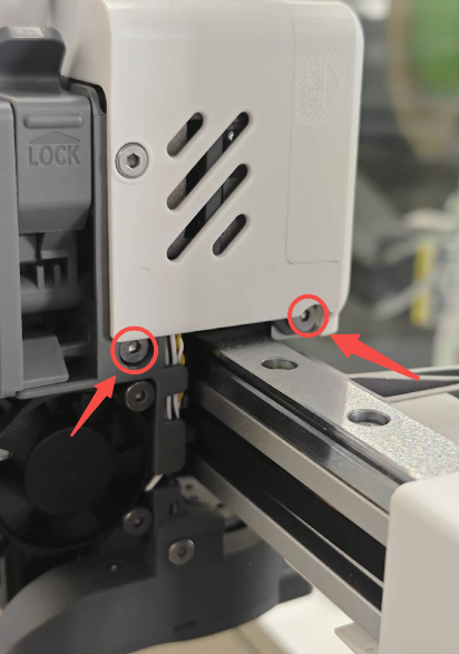
Unscrew the four screws on both sides of the toolhead to remove the entire toolhead, allowing access for the following steps.
 |
 |
 |
¶ Remove the Toolhead Rear Housing
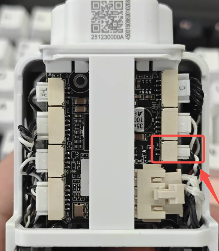
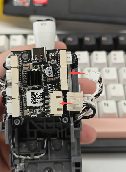
Remove the Toolhead Back Cover to expose the Toolhead Board. As shown in the figure, unplug the connector corresponding to the Extruder Cooling Fan.
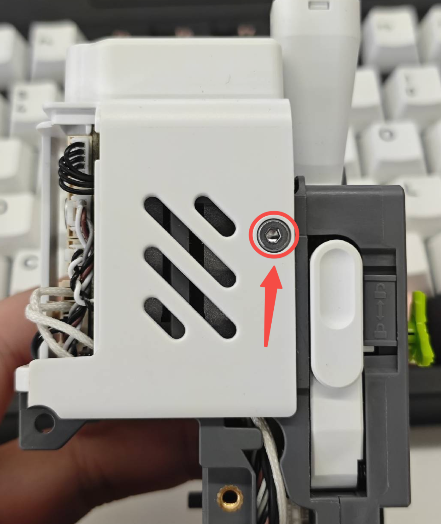
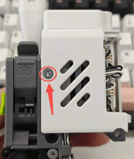
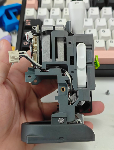
Use the H2.0 hex wrench to unscrew the two screws on both sides of the Toolhead Rear Housing, then lift and remove the Toolhead Rear Housing.
 |
 |
¶ Removing the Hotend Heating Assembly and Part Cooling Fan Assembly
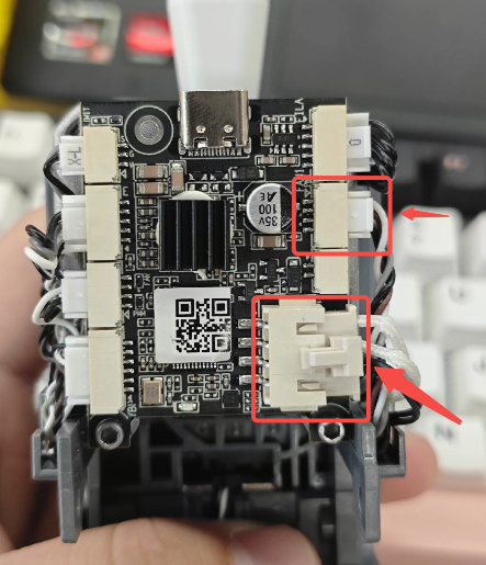
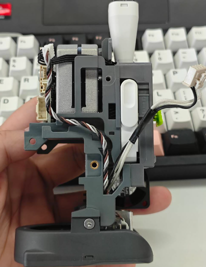
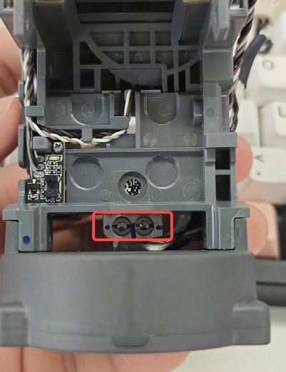
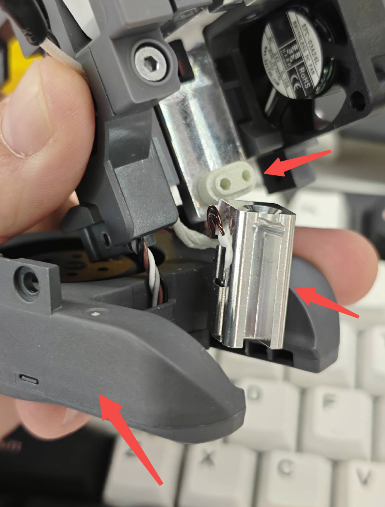
As shown in the figure, unplug the connectors of the Part Cooling Fan Assembly and the Hotend Heating Assembly, and carefully remove the cables from the cable channels.
 |
 |
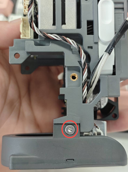
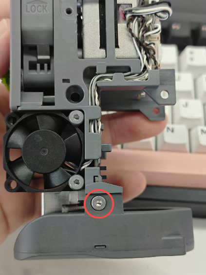
Unscrew the two screws on the back of the Hotend Heating Assembly to release it.Unscrew the two screws on both sides of the Part Cooling Fan Assembly to release the fan.
 |
 |
 |
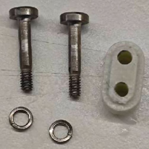
With both the Hotend Heating Assembly and the Part Cooling Fan Assembly loosened, you can more easily remove the Hotend Heating Assembly. Note: Do not lose the insulation block or the screw washers of the Heating Assembly.
¶ Installing the New Hotend Heating Assembly
Route the Part Cooling Fan Assembly cable back through the side hole and organize the wires neatly.
Prepare the new Hotend Heating Assembly, first pass its cable through the side hole. Make sure the cables for both the Heating Assembly and the Part Cooling Fan Assembly are properly arranged, and do not forget to install the insulation block.
Secure the Part Cooling Fan Assembly and the Heating Assembly with screws. Do not fully tighten the screws of the Heating Assembly yet.
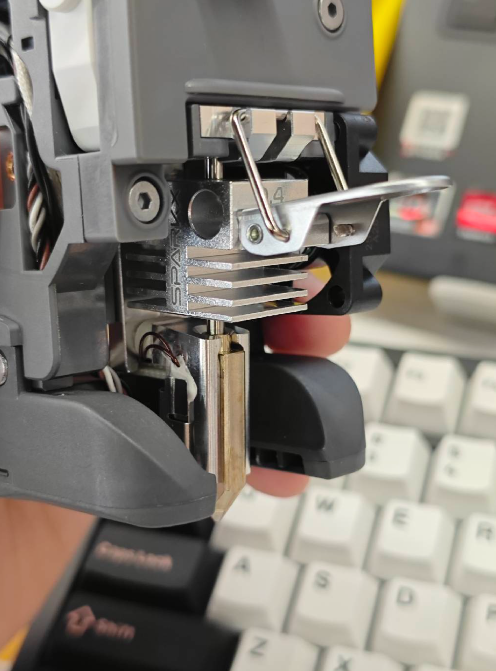
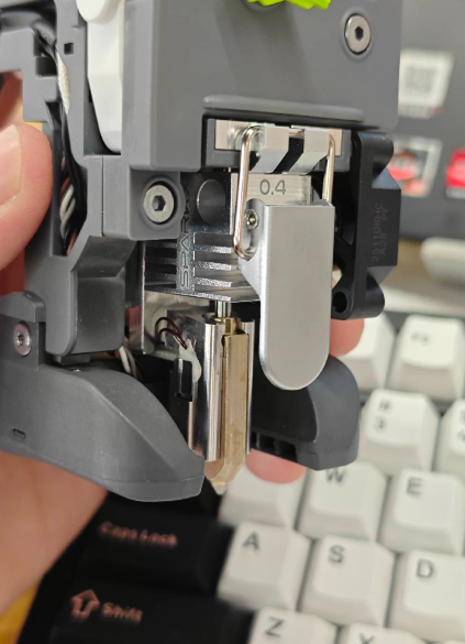
Insert the quick-release hotend back onto the toolhead and snap the latch to ensure it is properly seated. Then fully tighten the two screws of the Heating Assembly.
 |
 |
 |
Arrange the cables of the fan and Heating Assembly neatly in the cable channels, and plug them into the corresponding connectors on the Toolhead Board.
 |
 |
Reinstall the Toolhead Rear Housing, reconnect the Extruder Cooling Fan connector, secure the rear housing with screws, and snap the Toolhead Back Cover into place.
¶ Reinstalling the Toolhead onto the Printer
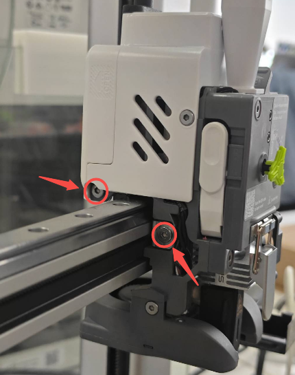
Mount the toolhead back onto the X-axis of the i7 and secure it with screws.
 |
 |
Reinstall the hotend sock and the toolhead front cover to complete all replacement steps.
After replacement, it is recommended to perform a machine calibration to ensure optimal operation. You can refer to SPARKX i7 Automatic Calibration Guide