¶ Preparation before carving
¶ 1. Preparation of items and materials
Before starting the engraving, please prepare the following items and materials for internal engraving. Please confirm that your equipment is configured with a UV 5W laser module and an internal engraving field lens - F130. If they are incompatible or you need to replace the module, please refer to the module replacement tutorial first.
Install the ultraviolet laser module and the internal engraving field lens (purple), ensuring a secure installation and proper connection. Refer to the field lens replacement operation guide for details.
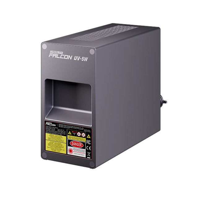 5W UV Laser Module |
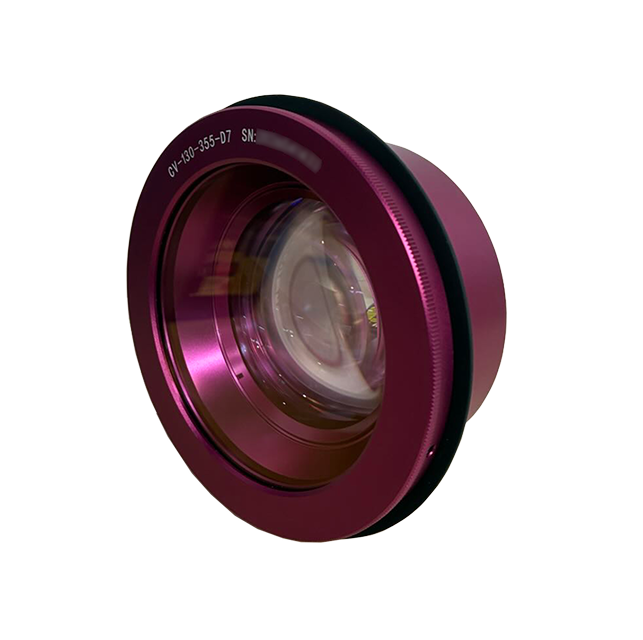 UV Internal Engraving F-theta Lens |
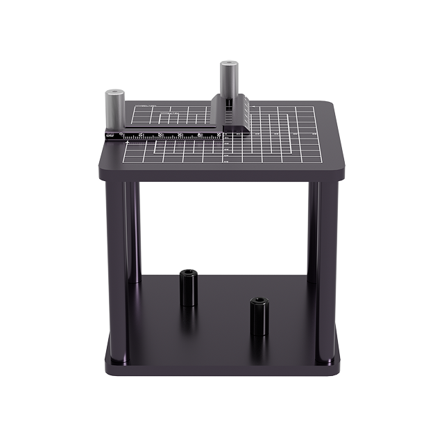 Heightening Stand |
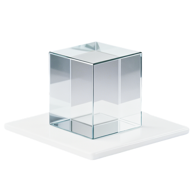 Crystal glass |
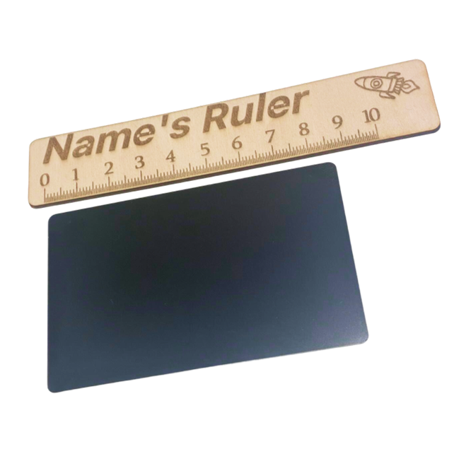 Anodized aluminum oxide |
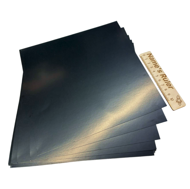 Laser engraving photo paper |
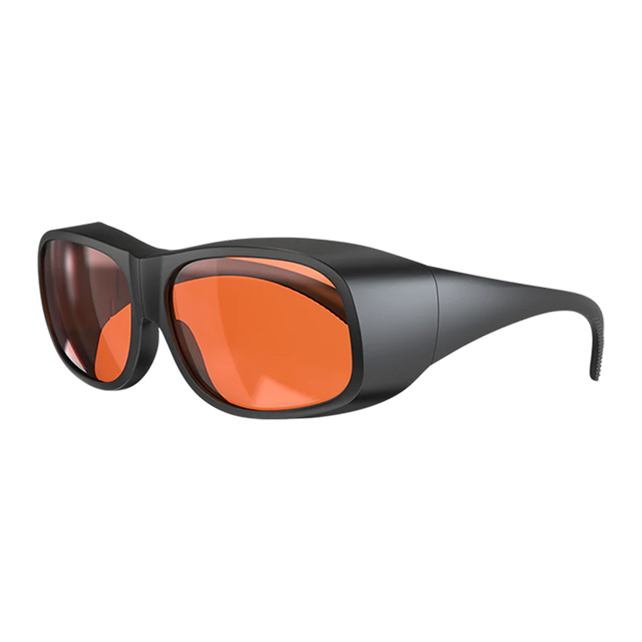 Protective glasses |
¶ 2、Software installation
Minimum software requirement: Falcon Design Space 1.10.1 Download link
Minimum device firmware requirement: 1.1.35
Please update to the latest firmware version in your device's "Settings - System".Firmware upgrade Operation Guide
¶ 3、Calibration
•Kind reminder: Please turn off the air purifier during the calibration process to avoid strong wind interference causing the calibration card to shift position.
Complete the following three calibrations in sequence:(1) Laser Module Calibration (2) Auto Focus Calibration (Skippable) (3) F-theta lens Calibration
Link to detailed calibration tutorial
¶ Operation Steps
¶ 1. Assembly & Positioning of Internal Engraving Stand
Detailed assembly guide for the internal engraving stand:https://wiki.creality.com/en/laser-engraver/falcon-t1/internal-engraving-stand-t1
¶ 1.1 Assemble the Stand
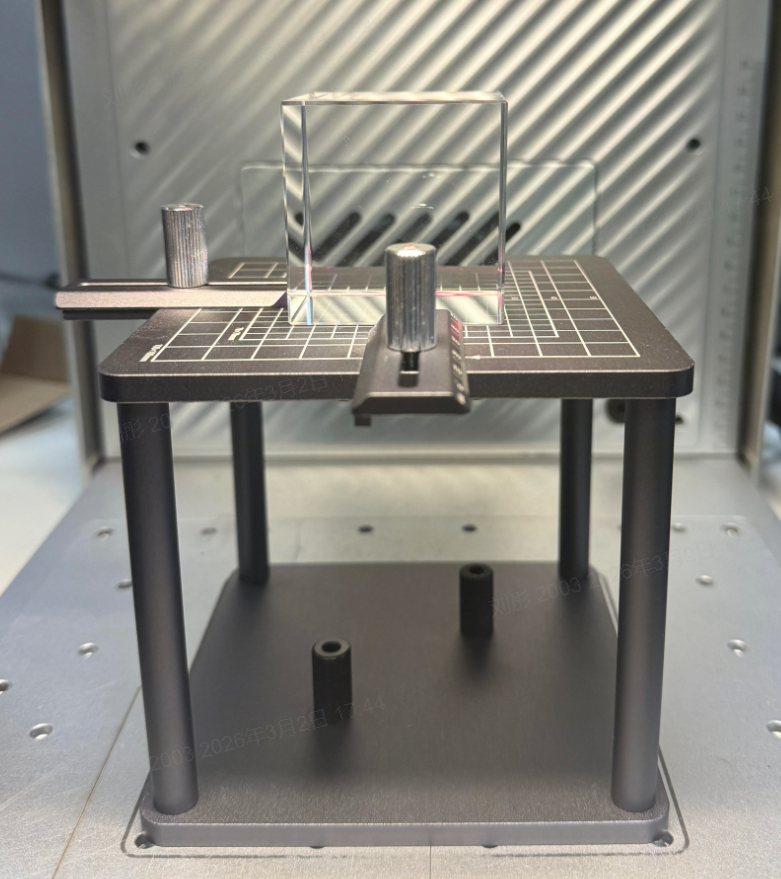
Screw the support pillars onto the base plate. Install the positioning rulers on the X and Y axes of the positioning panel respectively and tighten the screws. Then insert the positioning panel onto the support pillars.
¶ 1.2 Adjust the Positioning Rulers
Adjust the positioning rulers according to the actual size of the material to ensure the material is centered.Example: For a 50×50×50mm crystal, set the positioning rulers to 25mm.
¶ 1.3 Fix the Stand
Secure the fully assembled internal engraving stand at the center of the engraver’s working area.Do NOT lift only the working panel when moving the stand, to avoid component damage or positioning deviation.
¶ 2. Material & Model Preparation for Internal Engraving
¶ 2.1 Connect the Device
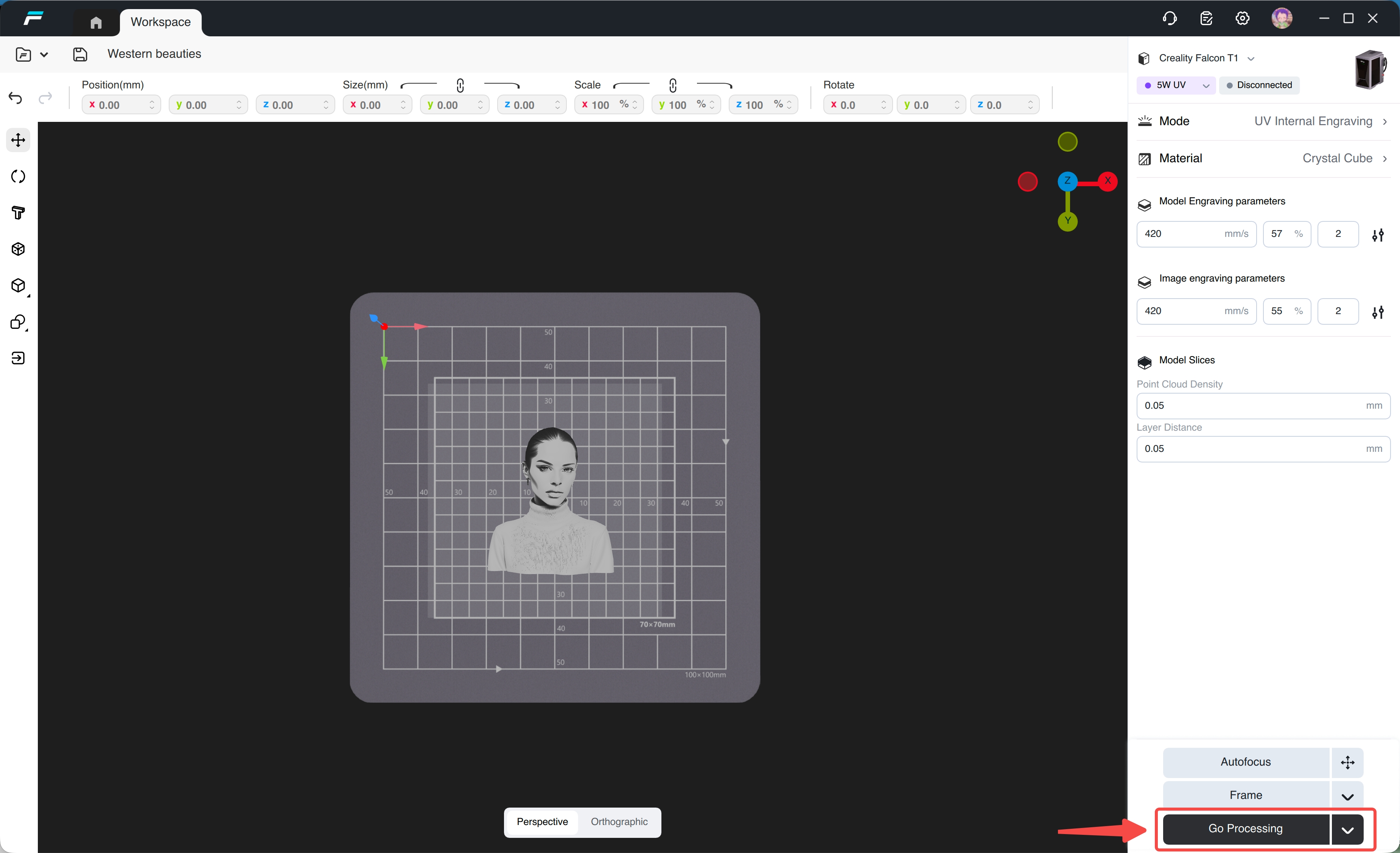
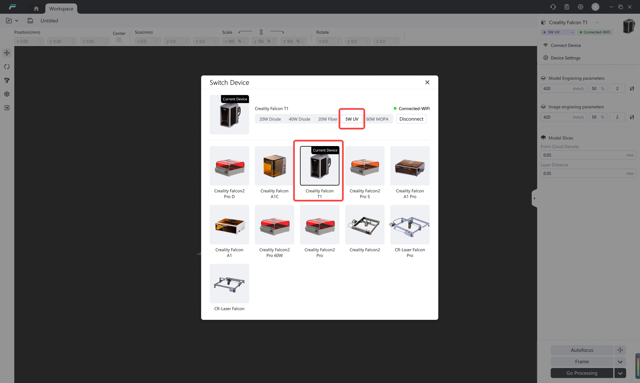
Open the FDS software, connect the device, and confirm it is Creality Falcon T1.Go to 【Workspace】 and select 【5W UV】 as the light source.

¶ 2.2 Select Processing Mode
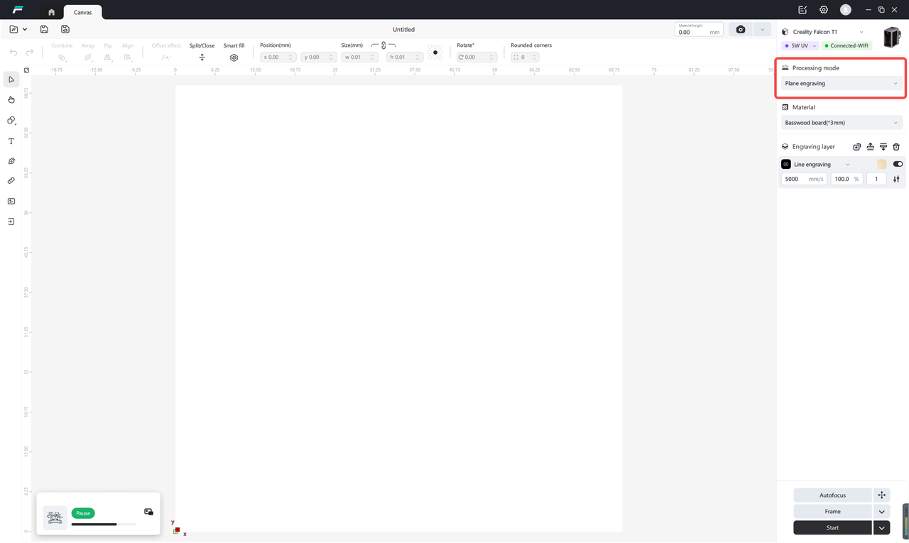
Click 【Processing Mode】
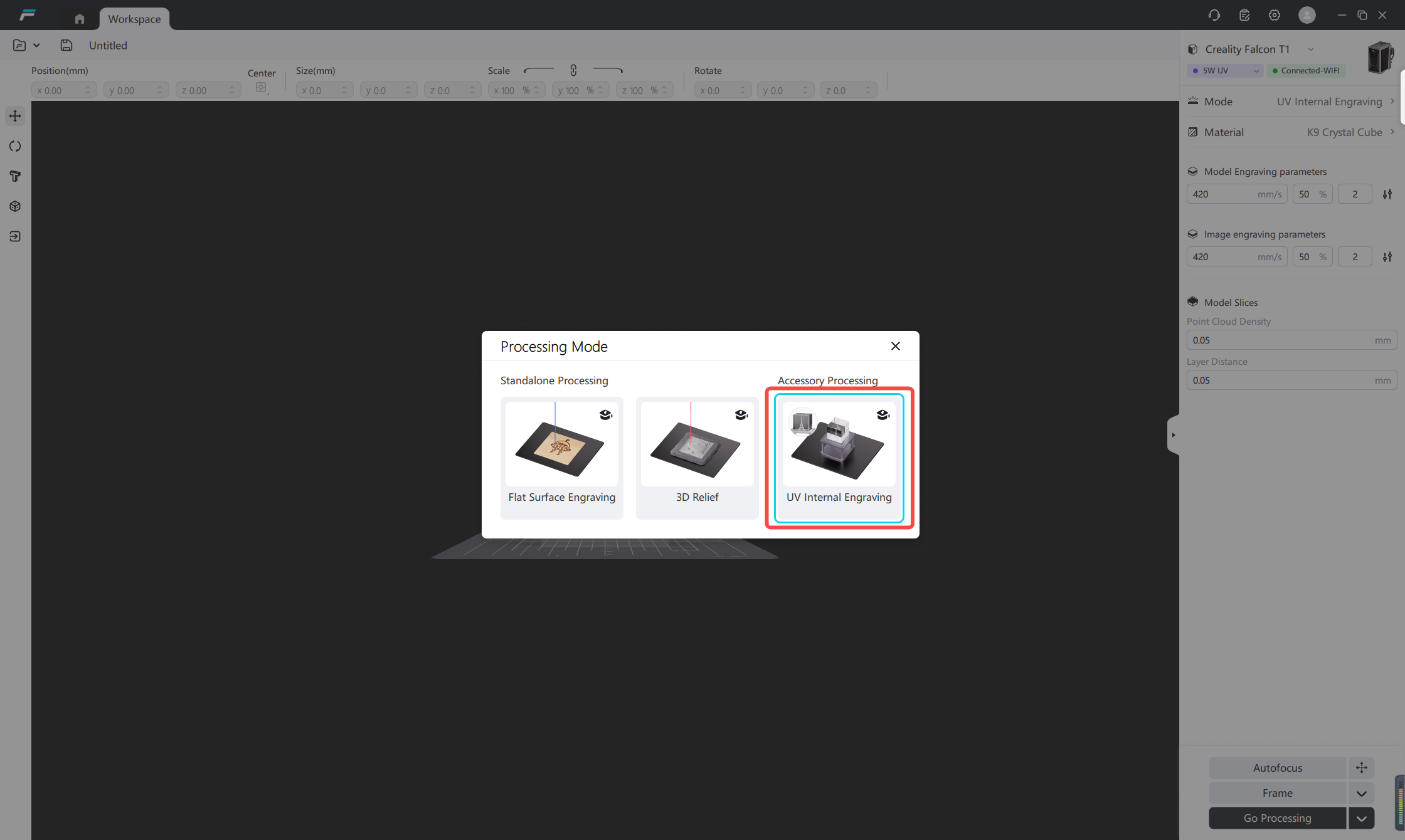
Select 【UV Internal Engraving】 mode.
¶ 2.3 Set Consumable Dimensions:
Click the 【Material】 tab.
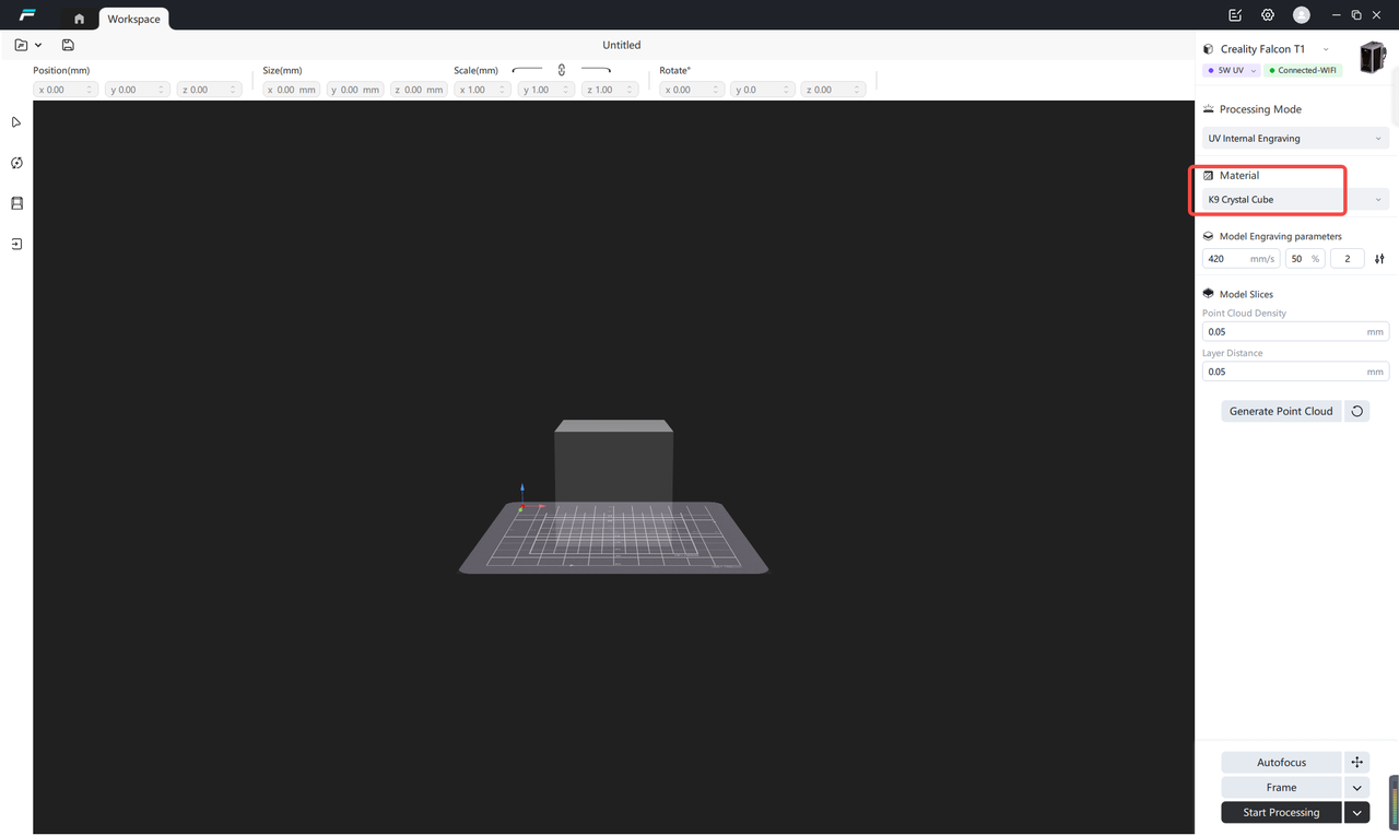
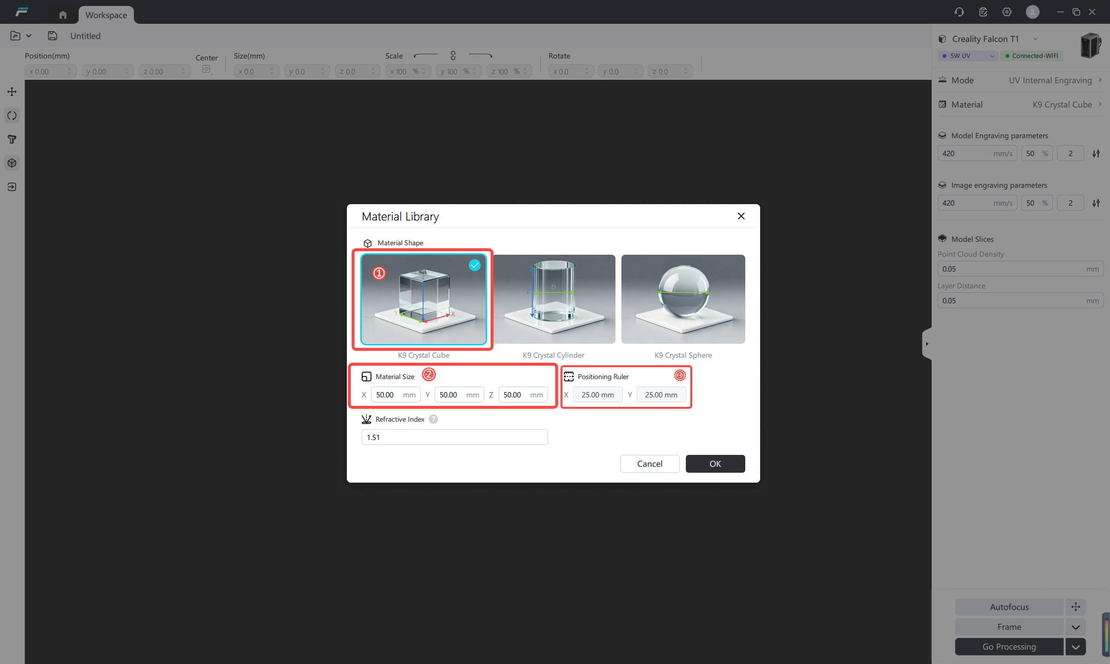
Select the shape of the consumable, and enter dimension parameters according to the actual specifications of the crystal. After inputting the material dimensions, the software will automatically calculate the coordinates of the positioning ruler. Adjust the scale marks on the positioning ruler of the internal engraving bracket as prompted by the coordinates to place the crystal in the center.
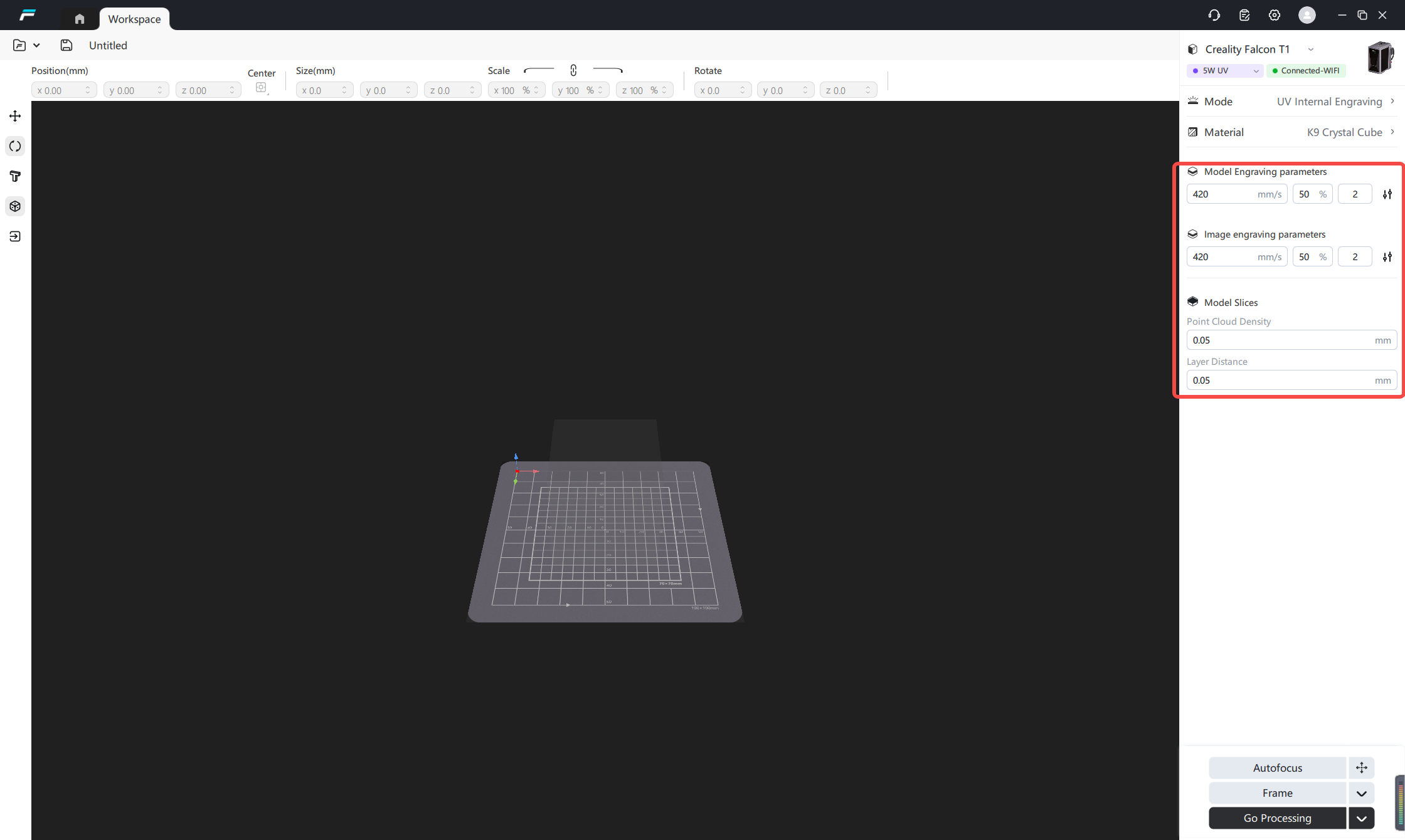
The software includes built‑in professional internal engraving parameters. Hover the mouse to view parameter descriptions.Modification is not recommended except for testing purposes.
Tip: When processing internal carving of crystal balls, it is necessary to cooperate with special processes to correct the spherical optical path. The curved surface of the crystal ball will cause irregular refraction and focal point shift of the laser, making it impossible to directly focus stably inside. This can be achieved bysolutionto make the top surface of the curved surface equivalent to a flat surface, allowing the laser to precisely focus inside the ball to complete the internal carving. That is, select internal carving oil/glycerin with a refractive index close to that of glass, high light transmittance, and safety and non-toxicity, place the crystal ball in a container of the same volume, pour in the solution to completely submerge it, and use the solution surface as a flat reference to compensate for spherical refraction, thereby achieving precise internal carving.
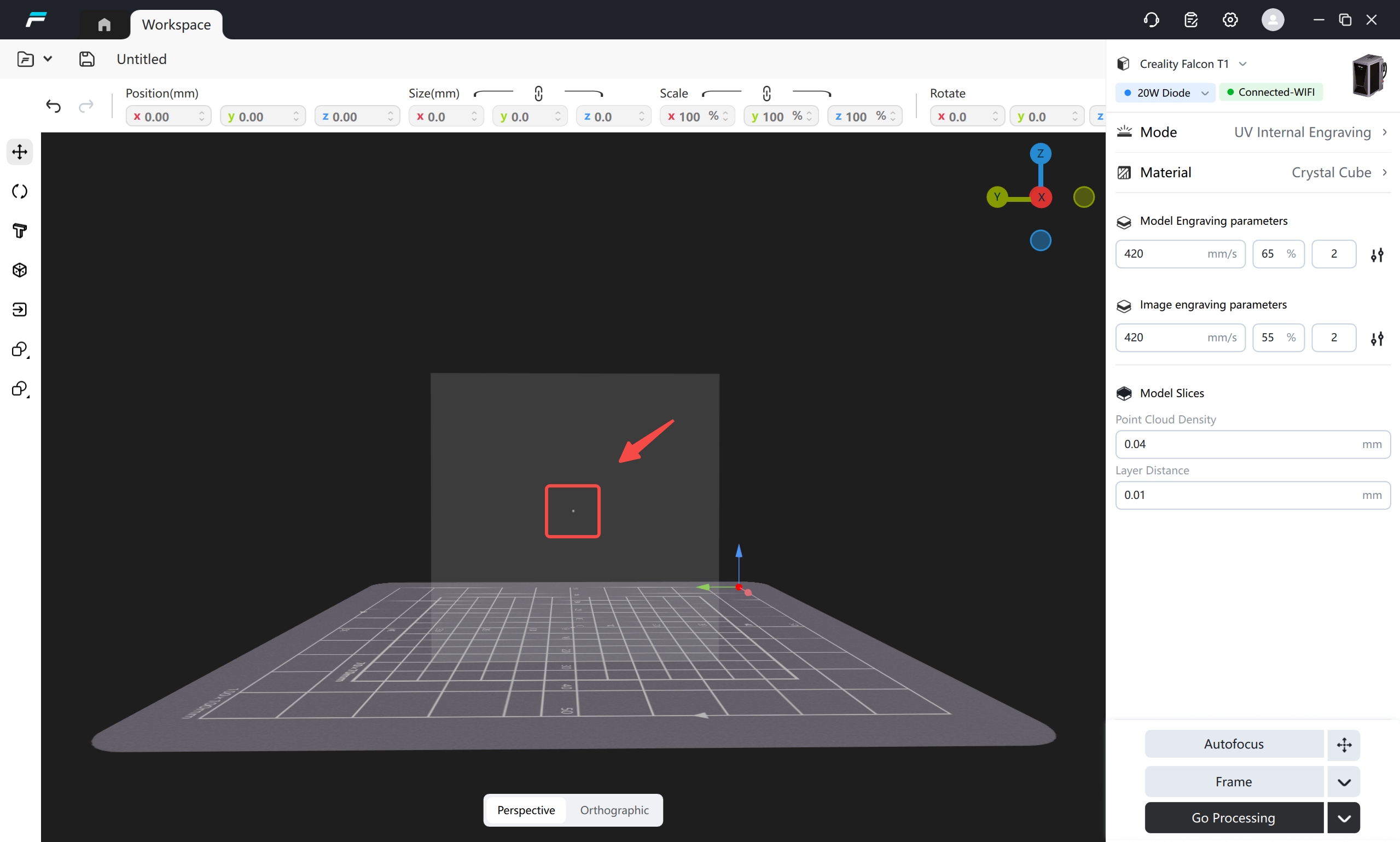
Warm Reminder: Fine-tuning of Model Sculpting Height (Recommendation for First Sculpting)
Due to cumulative factors such as refractive index, material quality, and measurement errors, the model preview position may deviate from the actual sculpting height by 1-3mm. It is recommended to first use scrap material to sculpt a small dot to test and locate the sculpting center. To ensure accurate positioning, it is recommended to first use scrap material to sculpt a small dot to test the center point, and then adjust the model position accordingly.
 |
¶ 2.4 Import Model (Supports importing 3D models, 2D images, and text internal carving):
Supports importing 3D models, images, vector graphics and FDS project files
Supported 3D formats:GLTF, GLB, OBJ, FBX, STL, 3MF, PLY
Supported graphic formats:BMP, JPG, JPEG, PNG, TIF, TIFF, SVG, DXF
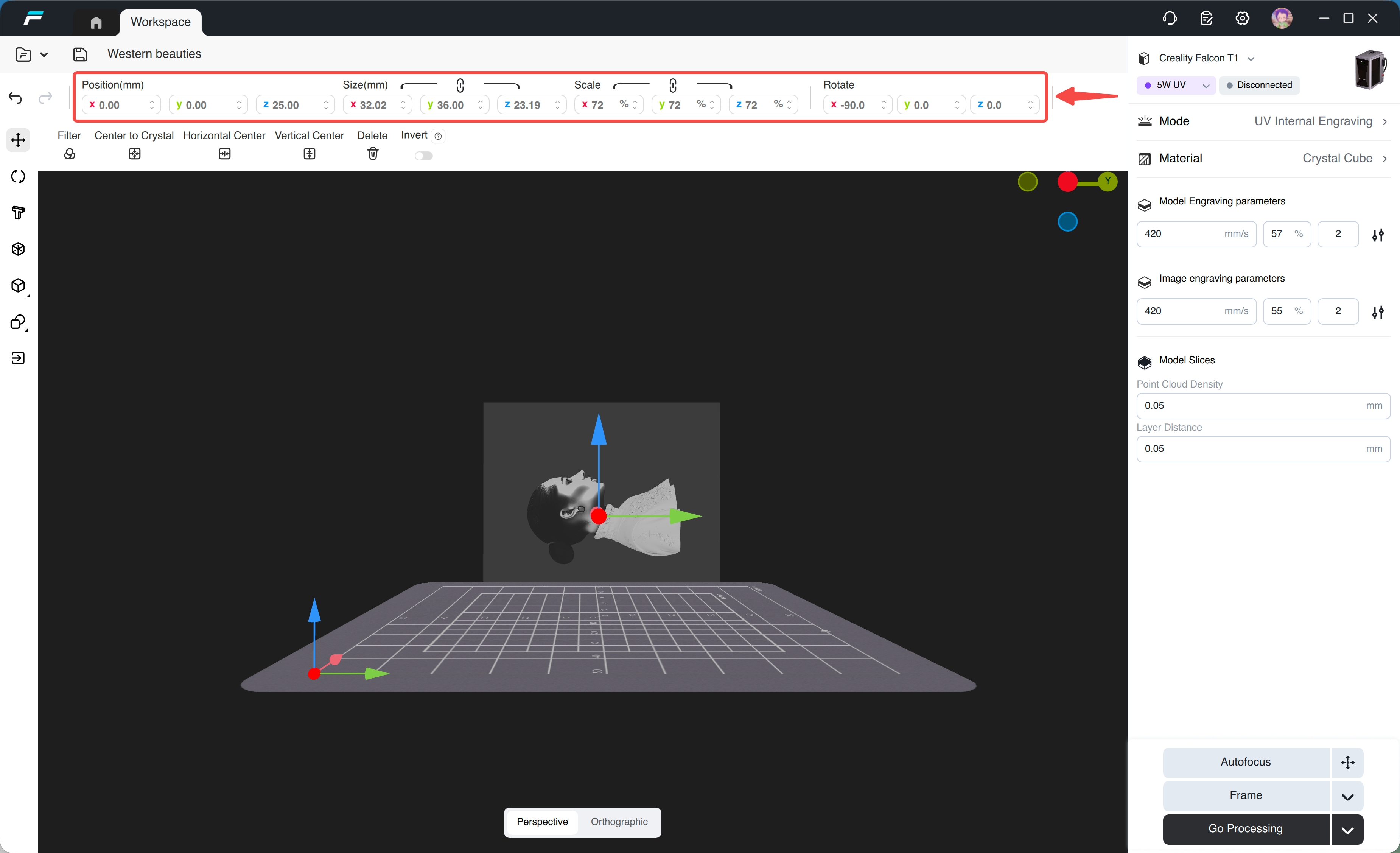
(1)Import 3D models / 2D images, click the import icon, select the model, and then control the position, size, and rotation angle by dragging or adjusting parameters
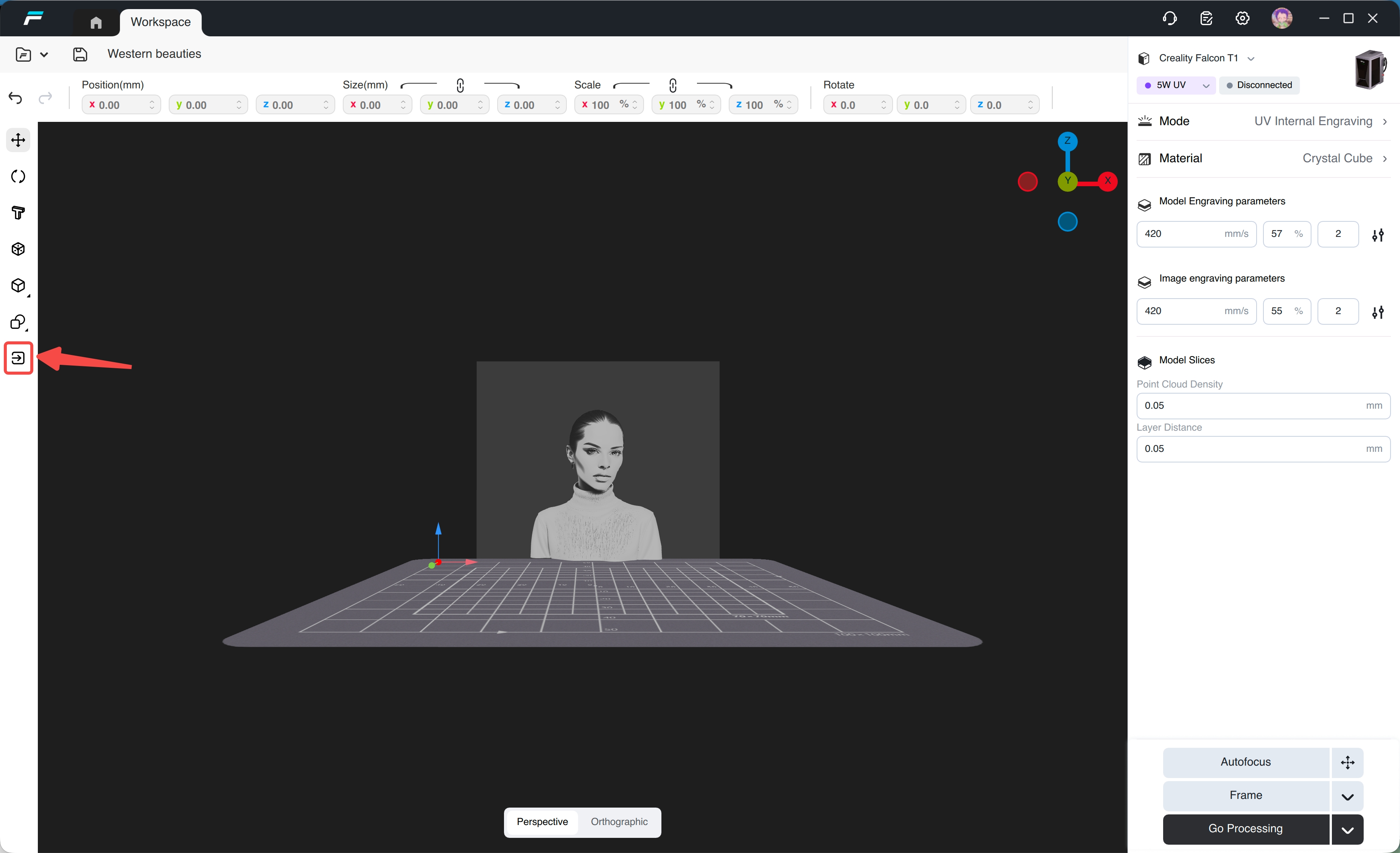
Select the model and adjust its position, size, and rotation angle by dragging or modifying parameters; press the Delete key to remove the imported model.
Tips: During internal glass engraving, micro-fractures within the material generate debris and stress, naturally creating burrs on the bottom surface. To ensure engraving clarity, rotate the model so that the clear front face points upward and the burred bottom face points downward. Scroll the middle mouse button to zoom, hold the middle mouse button to pan, and hold the left mouse button to rotate the view.
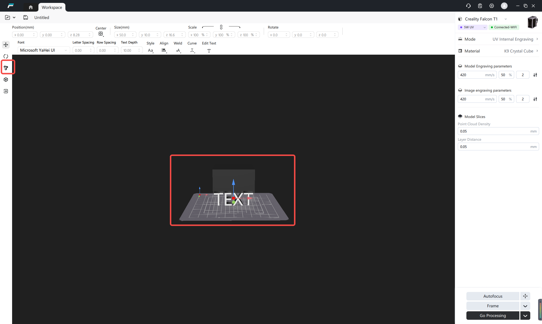
(2) Click the text icon to import text.
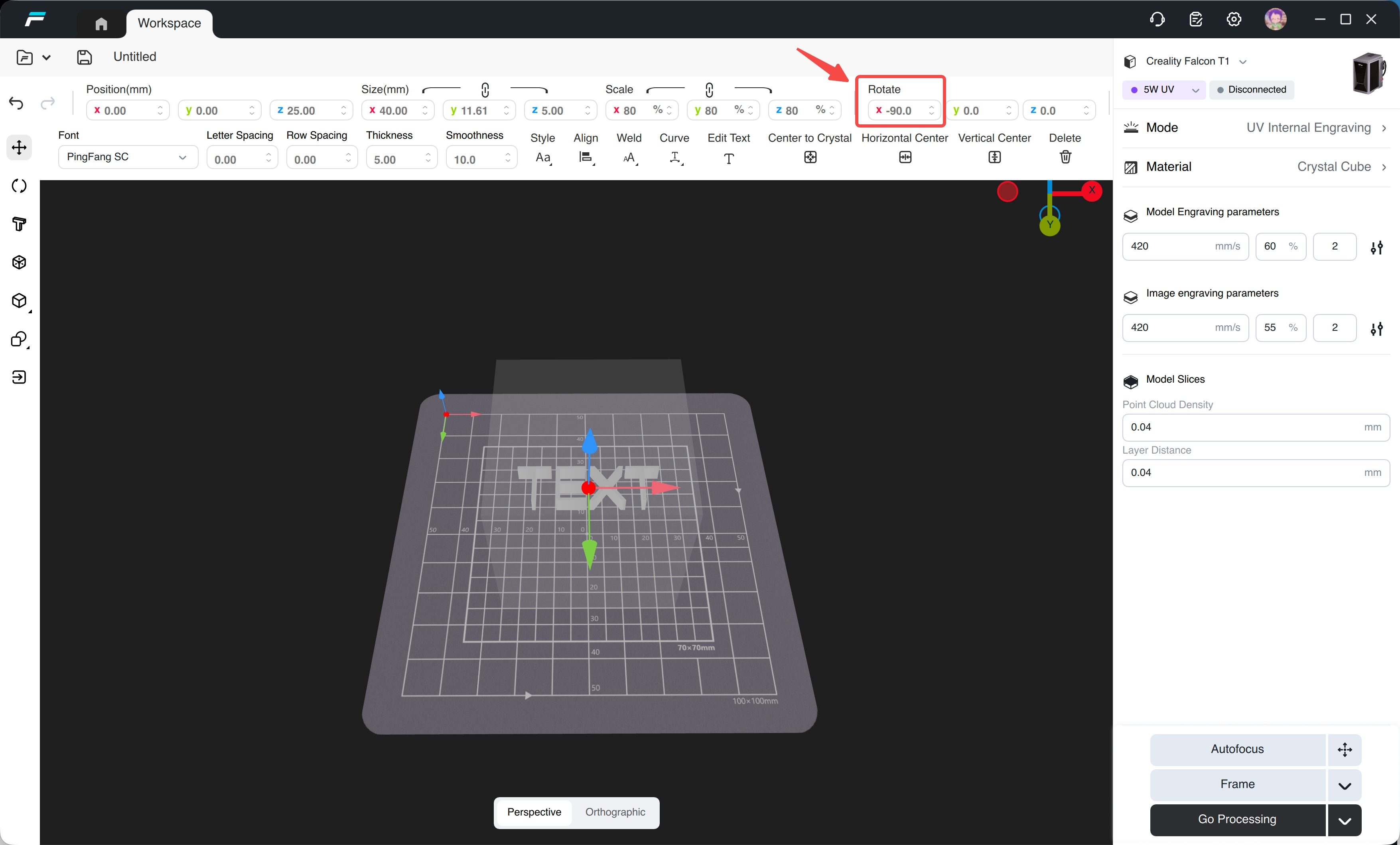
(3) Rotate the model by entering -90 for the X-axis rotation.
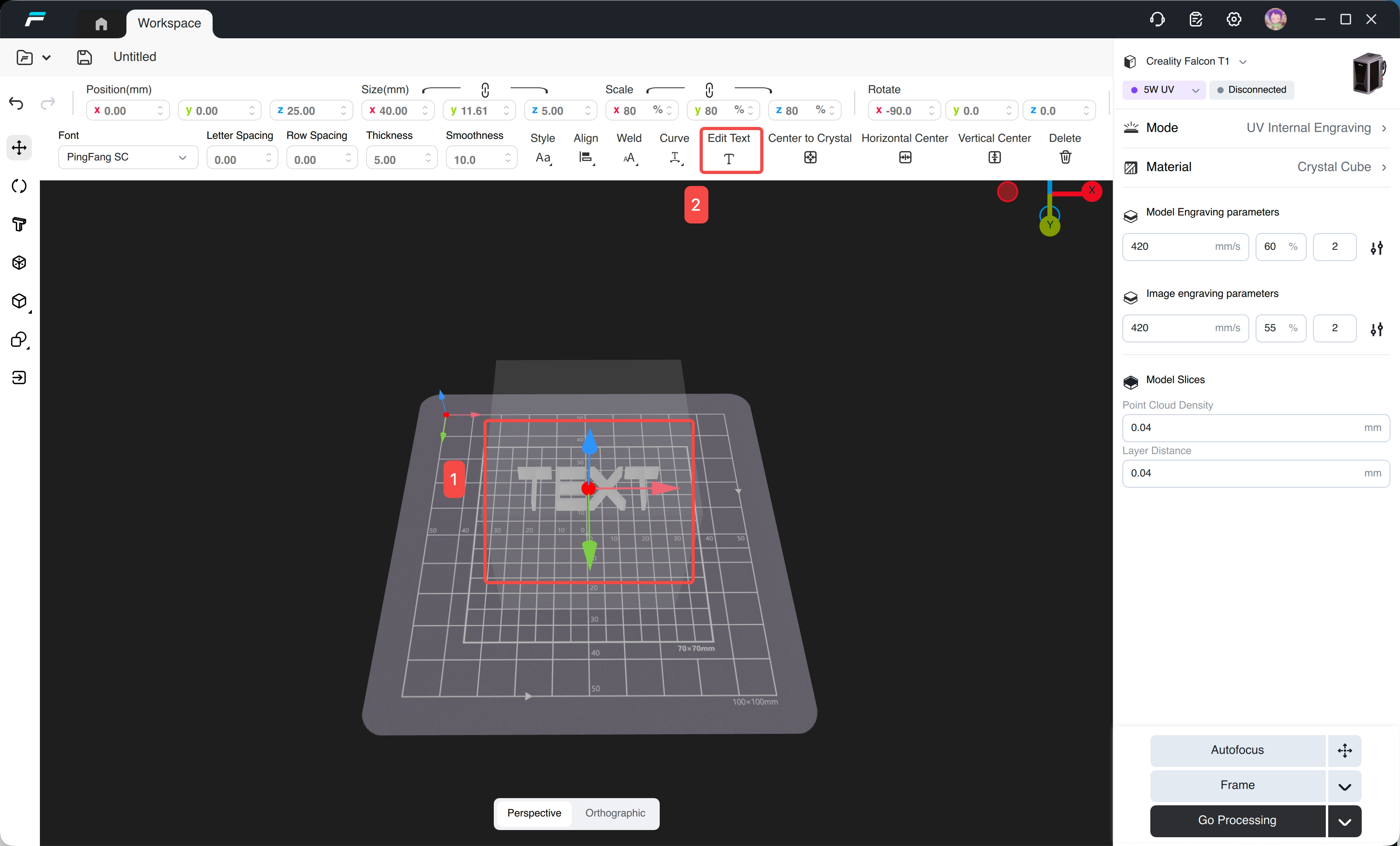
Select the text, click Edit Text, and you can edit the text
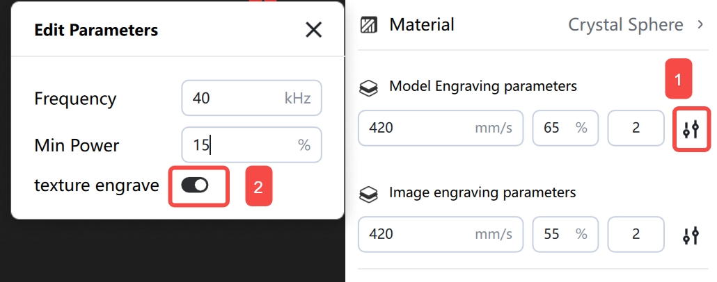
Note: For models with textures, it is recommended to enable the "Texture engrave" function to obtain richer details.
 |
¶ 3. Preview the internal engraving area
¶ 3.1 Auto Focus
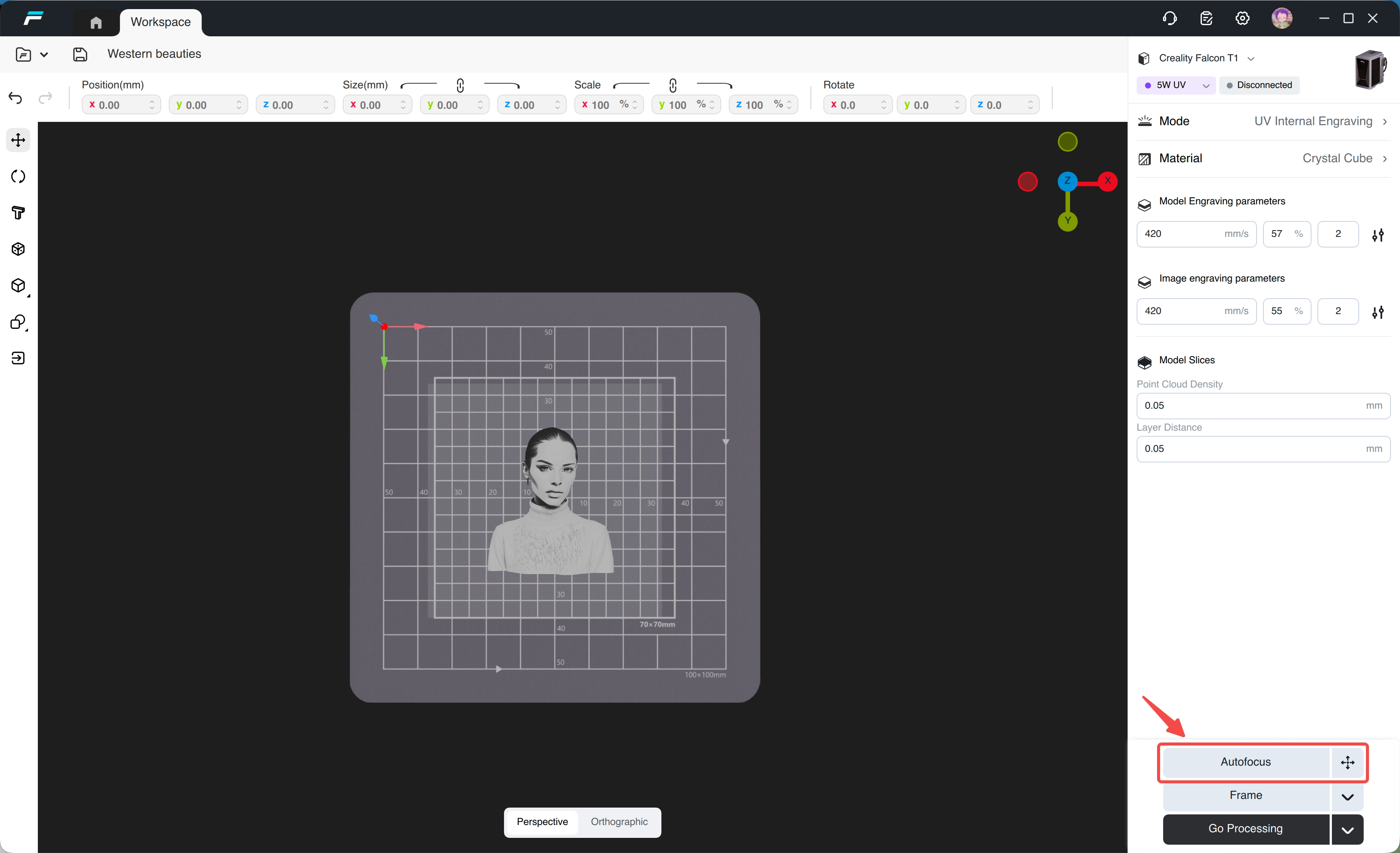
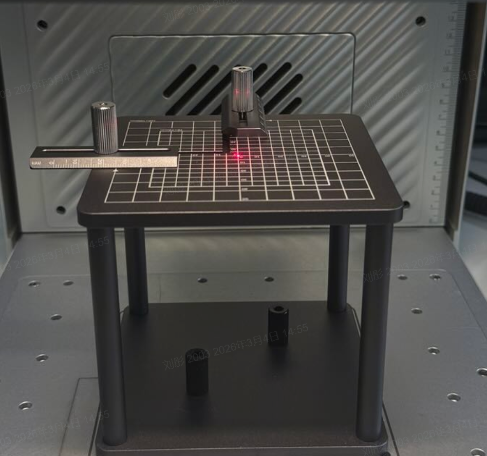
Perform auto‑focus directly on the assembled internal engraving stand.Do NOT place the crystal material at this stage. Correct focusing ensures an accurate border preview.
¶ 3.2 Frame
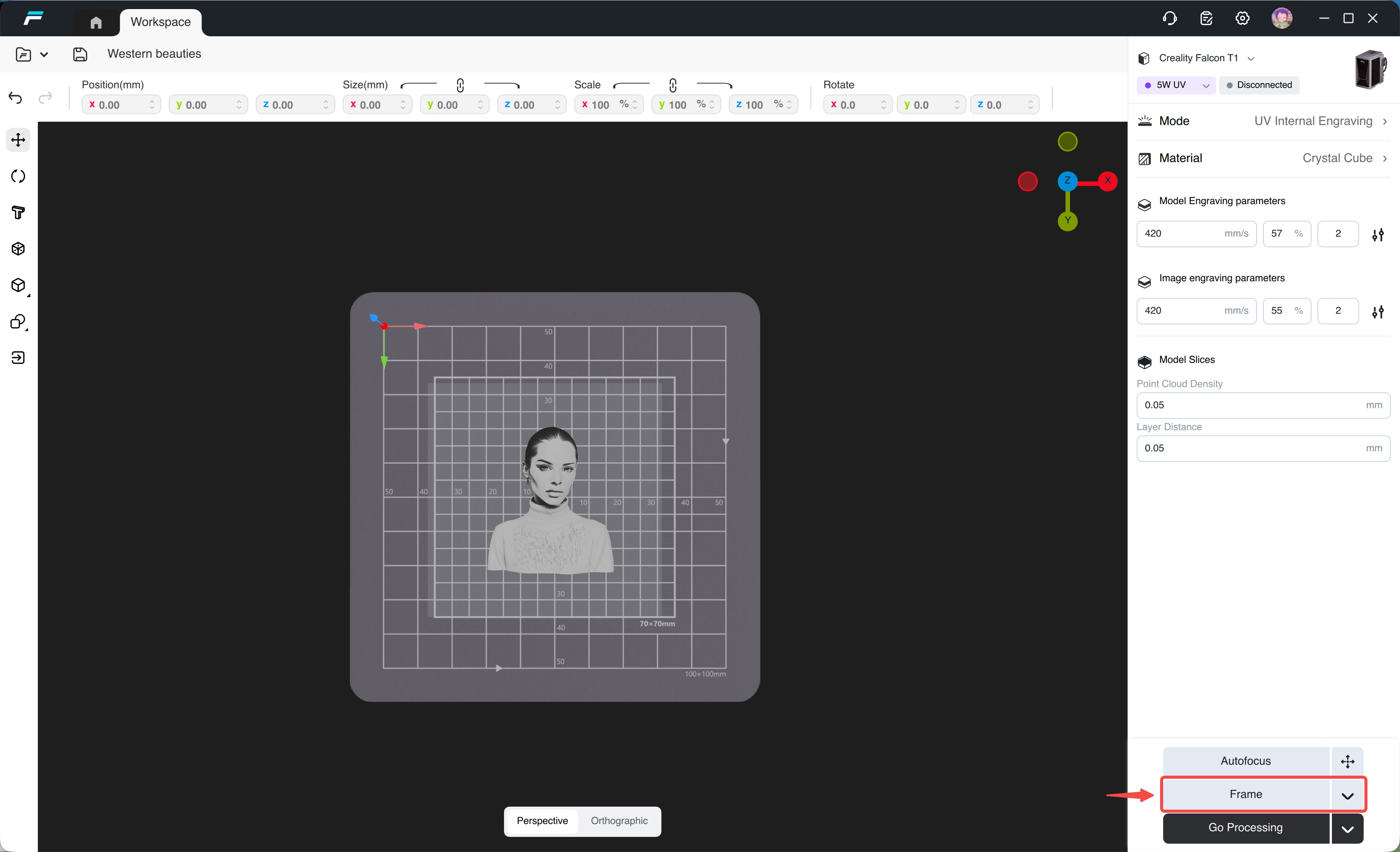
Click 【Frame】 to preview the actual engraving area on the internal engraving panel.Confirm the processing area before proceeding.

After previewing, place the crystal material tightly against the positioning rulers to keep it centered. Ensure the material is stable and not offset.
¶ 4. Start Internal Engraving
¶ 4.1 Start Processing
Click 【Start Processing】 to preview the full engraving path.After confirming no abnormalities, close the engraver protective cover, then click the start button to begin UV internal engraving.Do NOT open the protective cover during processing.