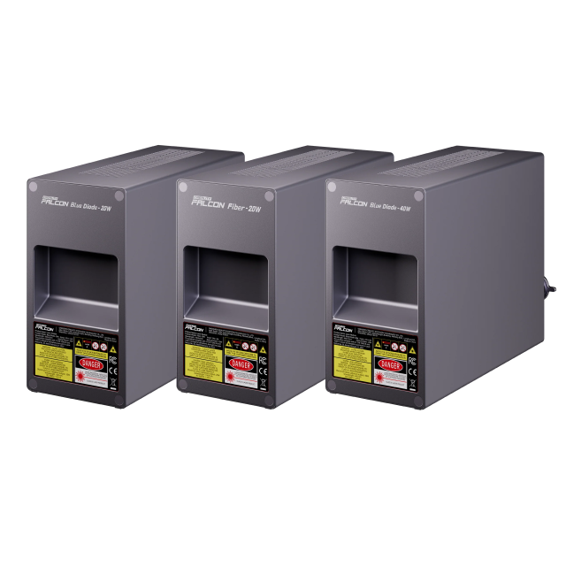
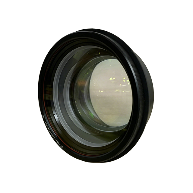
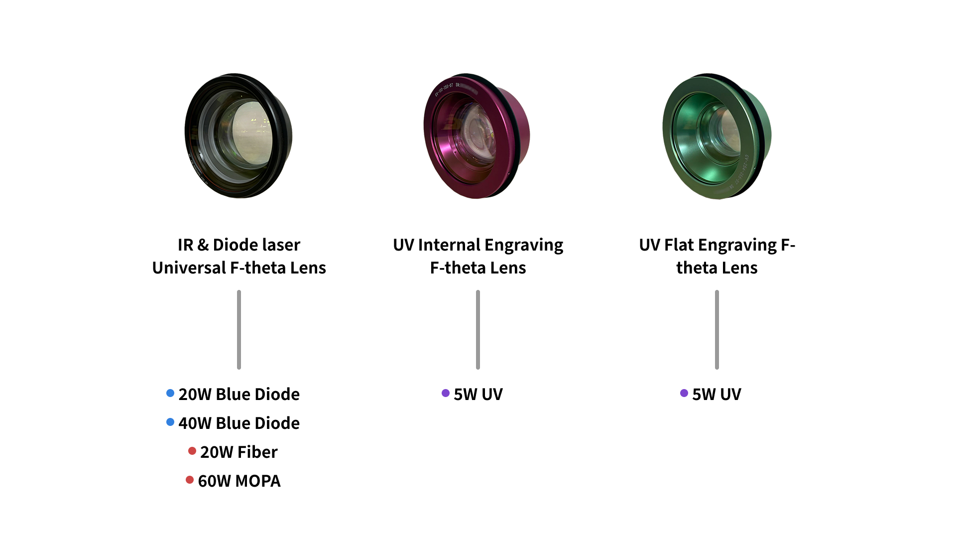
This tutorial applies to the adaptation and calibration of 20W Blue Diode / 40W Blue Diode / 20W Fiber / 60W MOPA with the IR & Diode laser Universal F-theta Lens (black)
¶ 1. Preparatory Work
Before starting the calibration, please prepare the following items and materials in advance
|
|
|---|---|
|
|
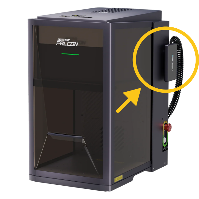
The device has been powered on, and the 20W Blue Diode / 40W Blue Diode / 20W Fiber / 60W MOPA laser module and the IR & Diode laser Universal F-theta Lens (black) have been correctly installed.
If it does not match or the laser module needs to be replaced, please first check the tutorial for replacing the laser module: https://youtu.be/-ZZXBVmFkyU
Ensure that the device firmware has been upgraded to the latest version (V1.1.29 or higher)
Please turn off the air purifier during the calibration process to avoid strong wind interfering with the position shift of the calibration card.
- The carving process will generate a certain amount of dust and fumes, please wear an N95 mask.
¶ 2. Important Safety Instructions
IR & Diode laser Universal F-theta Lens (black) is only suitable for Blue Diode / Fiber / MOPA laser modules , and it is strictly prohibited to mix with UV Internal Engraving F-theta Lens (purple) / UV Flat Engraving F-theta Lens (green)! Using a mismatched F-theta Lens will cause damage to the F-theta Lens.
During the calibration process, the laser is invisible ultraviolet light, so please be sure to wear protective glasses.
Do not start calibration with the cover open to avoid burns.
¶ 3. Instructions for Calibration Sequence
Laser Module Calibration → Auto Focus Calibration (Recommended, Skippable) → F-theta Lens Calibration
Please use the touch screen for calibration.
¶ 4. Fault Code Guide
Quick Troubleshooting Guide for Falcon T1 Series Fault Codes
- During the calibration process, if a fault code pop-up window appears, you can refer to this guide
¶ 5. Start calibration
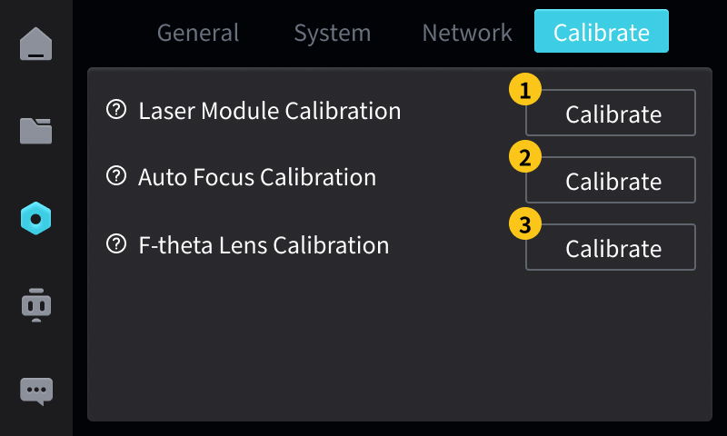
¶ Step 1: Laser Module Calibration
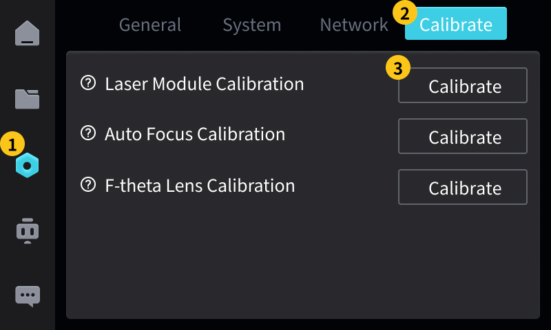
(1) Click the "Settings" tab
(2) Click the "Calibration" tab
(3) Click "Start Calibration"
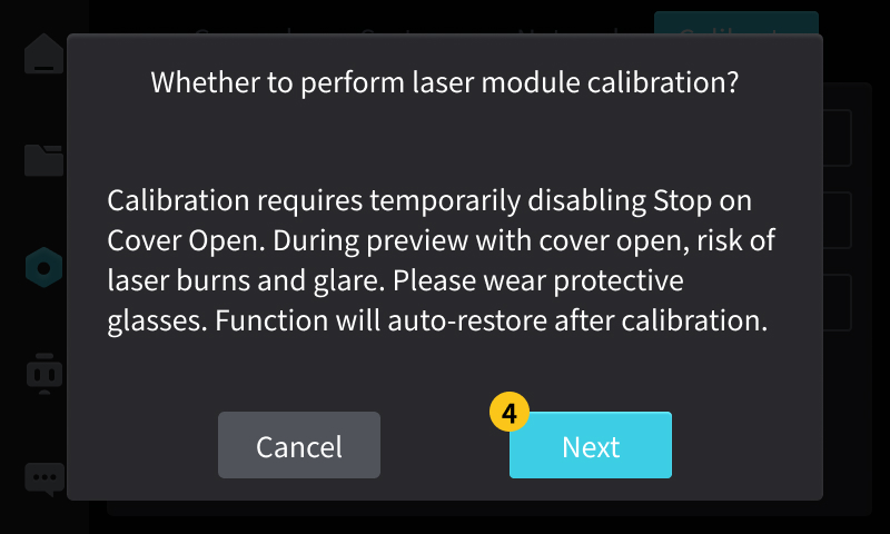
(4) Confirm to turn off the safety protection, then click "Next"
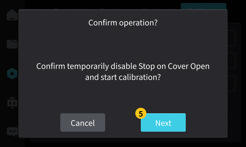
(5) Double-check and click "Next"

(6) Waiting for device preparation
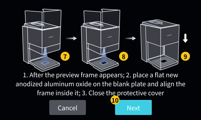
(7) Wait for the preview box to appear, then open the protective cover
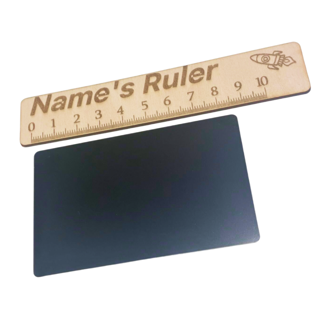
(8) Place the flat new anodized aluminum oxide (Laser Module Calibration Card) on the blank base plate, ensuring that the preview frame appears completely within the card and the corresponding edges are parallel and aligned.
- The card must be brand new, flat, and free of warping, and the preview frame must not exceed the card; otherwise, the calibration result may be inaccurate.
(9) Close the protective cover
(10) Click "Next"
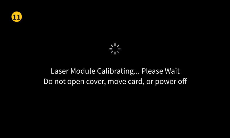
(11) Waiting for device calibration
- Do not open the protective cover or shake the device during the process, otherwise the calibration results may be inaccurate.

(12) Calibration completed, click "OK", open the protective cover, and remove the anodized aluminum oxide (Laser Module Calibration Card)
- Calibration completion indicates successful calibration (no error pop-up)
- The exhaust fan will delay shutting down, and when the pop-up window appears, the task has already ended
¶ Step 2: Auto Focus Calibration (Recommended, Skippable)
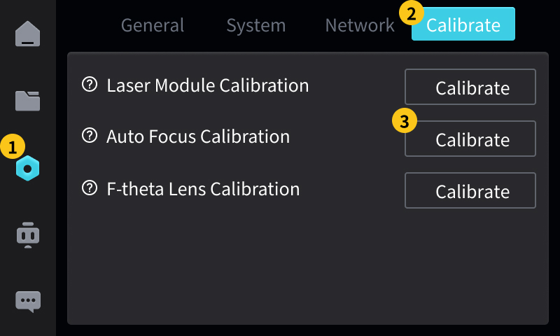
(1) Click the "Settings" tab
(2) Click the "Calibration" tab
(3) Click "Start Calibration"
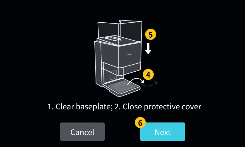
(4) Empty the device baseplate and ensure it is clean and free of debris
- Includes removing the Calibration Stand / Internal Engraved Stand (if any)
(5) Close the protective cover
(6) Click "Next"
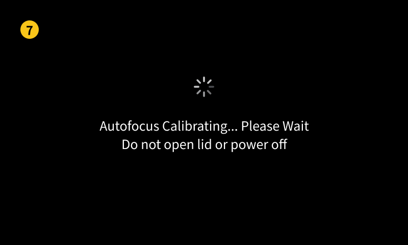
(7) Waiting for device calibration
- Do not open the protective cover during this process, nor do you need to place any auxiliary materials. Just wait patiently (usually a few dozen seconds)
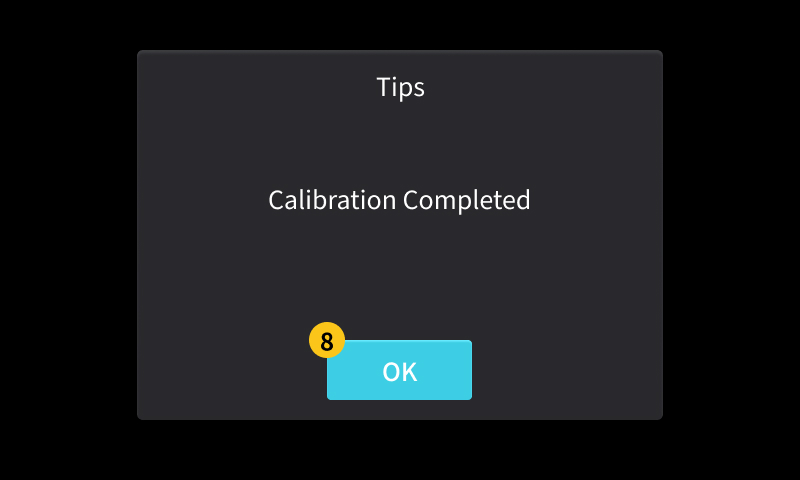
(8) Calibration completed, click "OK"
- Calibration completion indicates successful calibration (no error pop-up)
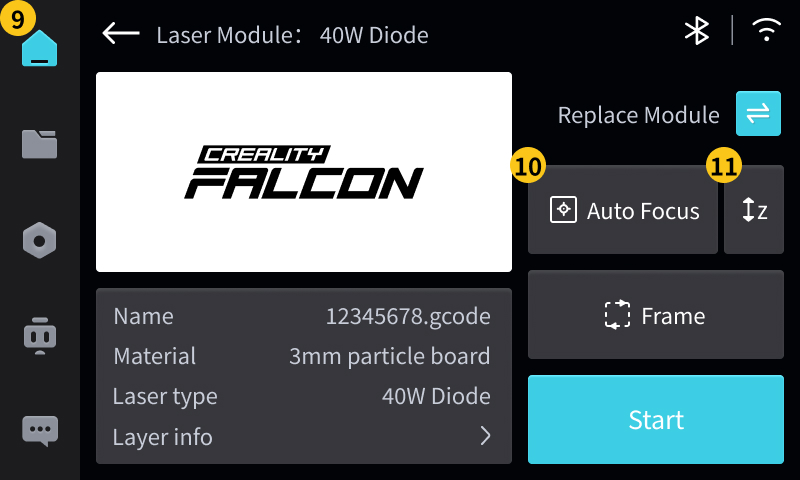
(9) Return to the "Workspace" to verify the calibration effect
(10) Click "Auto Focus" and wait for auto focus to complete
(11) Click "Manually Adjust Z Axis"
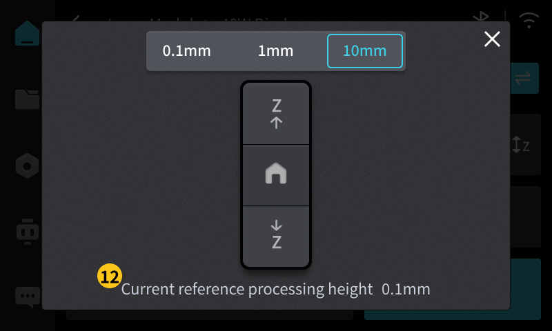
(12) Observe whether the value of "current reference machining height" is less than or equal to 0.5mm. During subsequent machining, the equipment will automatically focus according to the material thickness to complete the adaptation of the focal length.
- 0mm to 0.5mm is the normal fluctuation value
- If it is greater than this value, please re-run the "Auto Focus Calibration"
- If the issue cannot be resolved, please contact after-sales customer service
¶ Step 3: F-theta Lens Calibration

(1) Click the "Settings" tab
(2) Click the "Calibration" tab
(3) Click "Start Calibration"
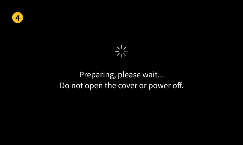
(4) Wait for device preparation
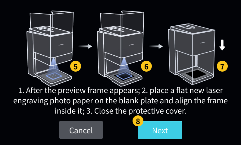
(5) Wait for the preview frame to appear, then open the protective cover
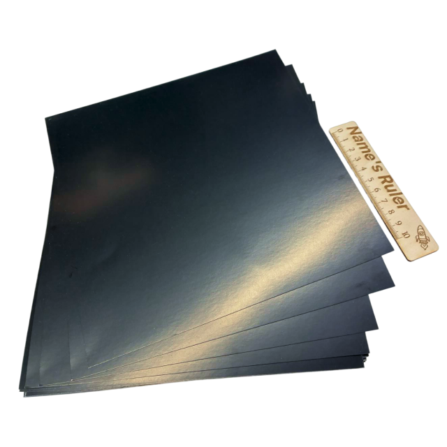
(6) Place the flat new laser engraving photo paper (F-Theta Lens Calibration Card) on the blank base plate, ensuring that the preview frame appears completely within the card and the corresponding edges are parallel and aligned.
- The card must be brand new, flat, and free of warping, and the preview frame must not exceed the card; otherwise, the calibration result may be inaccurate.
(7) Close the protective cover
(8) Click "Next"
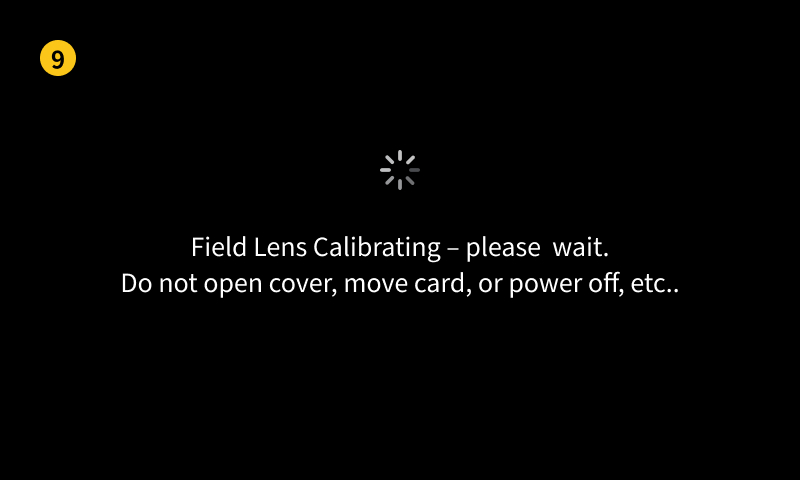
(9) Waiting for device calibration
- Do not open the protective cover or shake the device during the process, otherwise the calibration results may be inaccurate.

(10) Calibration completed. Click "OK", open the protective cover, and remove the laser engraving photo paper (F-Theta Lens Calibration Card)
- Calibration completion indicates successful calibration (no error pop-up)
- The exhaust fan will delay shutting down. When the pop-up window appears, the task has already ended.
¶ 6. Calibration completed
Now your Blue Diode / Fiber / MOPA Laser Module + IR & Diode laser Universal F-theta Lens (black) has completed all calibrations and can be safely and accurately put into production use.
- After calibration is completed, "Stop on cover open" will automatically restart. However, to ensure safety, it is recommended to check whether "Stop on cover open" is enabled to avoid injury caused by light leakage.
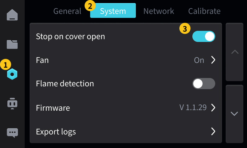
- (1) Click the "Settings" tab
- (2) Click the "System" tab
- (3) Check if the "Stop on cover open" switch is turned on. If it is off, please turn it on.