¶ Preface
Replacing the mainboard requires careful operation. Incorrect installation may cause the device to malfunction or damage other components. Please follow the steps below strictly.
¶ 1. Preparation
¶ Tools
Hex screwdrivers (1.5mm, 2mm, 2.5mm, 3mm)
Tweezers (for handling small screws or cables)
Spare screw box (to prevent losing screws)
New mainboard (ensure the model matches the original)
¶ Safety Tips
Power off: Unplug the power cord to ensure the device is completely powered off. (And unplug all wires on the right panel).
Photo documentation: Take photos of mainboard connection positions before disassembly for later reference.
¶ 2. Operation Steps
¶ Remove the Old Mainboard
Open the inner side panel of the case, locate the fixing screws. Use screwdriver to remove screws and gently take off the side panel.
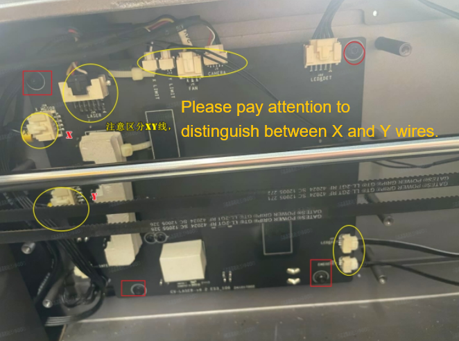
As shown in the yellow circles, unplug all cables from the mainboard. (Note: White ports have latches, press gently when unplugging to avoid damage.)
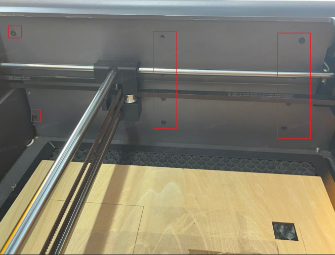
After unplugging the mainboard cables, remove the mainboard screws at positions marked by red circles.
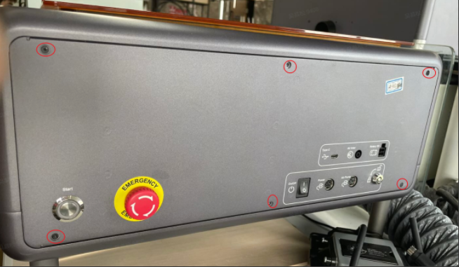
Locate the screws fixing the outer side panel, use screwdriver to remove screws and gently take off the side panel.
Find the air pump silicone tube on the mainboard, gently pull it out, unplug the remaining wires to remove the mainboard.

¶ Note:
Pay attention to different screw lengths, recommend sorting them separately.
Lift the mainboard gently to avoid scratching PCB or pulling remaining cables.
Check for hidden fixing clips to avoid forced removal.
¶ Install New Mainboard
Place the new mainboard and reconnect the air pump silicone tube.
Align the new mainboard with case screw holes, ensure correct installation direction, then install the outer side panel.
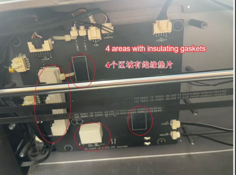
Replace new mainboard: Need to remove insulation gaskets from old mainboard and attach to new mainboard.
¶ Fix the Mainboard
Use original screws to fix mainboard to outer side panel, tighten in diagonal sequence (avoid board deformation).
Don't overtighten screws to prevent PCB damage.
Reconnecte the cables.
Please note that while XY motor wires need to be distinguished, other connections are fool-proof and can be connected normally.
¶ Test and Debug
- Perform initial power-on test, install two inner panels after confirming normal power-on
- Power on the device and observe:
Whether the power LED shows green light, start ring indicator lights up or not. (Light up indicates normal power supply)
Whether the fan rotates normally or not (rotating fans indicate normal cooling)
Whether the laser module responses normally or not.
- Software Check
Connect to computer, open laser control software (like FDS, Lightburn).
Check device recognition, test laser emission.
Firmware updates (If necessary, you can update firmware by this link Falcon A1 firmware download)
If new mainboard version differs, firmware flashing may be needed.((Refer to official Wiki tutorial: Falcon A1 Mainboard Firmware Update Guide)
¶ Complete Installation
Perform final engraving test to ensure stable device operation.
¶ Friendly reminder
If you still haven't resolved the issue after following the steps in this document, or if you encounter any difficulties during the process, you can click the right corner of the wiki page online support to contact our after-sales team for more help.