¶ Which Objects Should You Start With?
First, check the minimum scan size supported by your scanner:
- Ferret series: Minimum 50 × 50 × 50 mm.
- Otter series & Pika: Minimum 10 × 10 × 10 mm.
- Raptor & Sermoon series: Minimum 5 × 5 × 5 mm.
.png)
.png)
¶ How to scan the bottom of an object?
For Infrared Mode, when using geometry or texture tracking, you can flip the object directly. Aim the scanner at an already scanned area, then click the Start button to begin scanning. After tracking becomes stable, gradually move the scanner toward the unscanned area.
For Marker Mode, both Infrared Mode and Blue Laser Mode allow direct flipping only when markers are attached directly to the object itself. Aim the scanner at the already scanned markers, then click the Start button to begin scanning.
If markers are placed on the surrounding environment, do not flip the object.
.png)
¶ The scan data appears stretched, keeps rotating, or shows tracking misalignment. How to Prevent Tracking Loss?
Issue Example 1: "Scan data appears stretched" occurs when scanning objects with large flat surfaces.
Issue Example 2: "Scan data keeps rotating" occurs when scanning spherical, circular, or symmetrical objects.
Issue Example 3: Tracking failure and misalignment occur on small objects.
Possible Causes:
- Scanning movement too fast.
- Insufficient surface features/geometry.
- Improper scanning distance leading to tracking loss.
- Object size falls below the scanner's minimum scan range, or incorrect scan parameters (tracking mode, object size setting, exposure too high/low, improper resolution setting).
Solutions:
- Slow down the scanning speed – ensure the scanner can stably track the object surface.
- Switch to marker tracking mode – attach markers to or around the object.
.png)
- In Geometry Mode, place other objects with rich geometric features nearby (without occluding the target) to enhance geometric feature detection.
.png)
- Confirm the object size is within the scanner's scan range, and select the correct mode and parameters in the scan settings.
¶ Ghosting or Duplicate Point Clouds
.png)
.png)
Possible Causes:
- Insufficient object features – alignment errors occur after tracking recovery.
- Object placed on the calibration board during scanning (the board's pattern interferes with tracking).
- Markers arranged too regularly (e.g., straight lines, triangles, circles), causing abnormal recognition by the scanner.
Solutions:
- If misalignment has already occurred, check if insufficient features are the cause. Add more features, or use markers with marker tracking mode and rescan.
- Do not place the object on the calibration board.
.png)
.png)
.jpg)
¶ Scanner Does Not Capture Object Data
Possible Causes:
- Poor lighting conditions – sunlight (outdoors or through windows) interferes with the sensor's ability to detect the object.
- Improper scanning distance – resulting in data acquisition failure.
- Special material properties – the object surface is pure black, highly reflective, or transparent.
- Incorrect scan parameters – exposure too high/low, or resolution set too large.
Solutions:
- Avoid scanning in environments with strong lighting. If you need to scan outdoors, it is best to do so at dusk or on an overcast day. At dusk, there is still enough ambient light for scanning, while direct sunlight is less likely to shine on the object being scanned.
- Keep the scanning distance within the optimal range.
- For highly reflective or transparent objects, apply scanning spray first. For detailed instructions, refer to: How to Scan Black/Reflective/Transparent Objects.
- Adjust exposure settings to suit different materials. Example with a black mouse:
Infrared Mode: Adjust IR exposure until the preview point cloud is clear and complete.
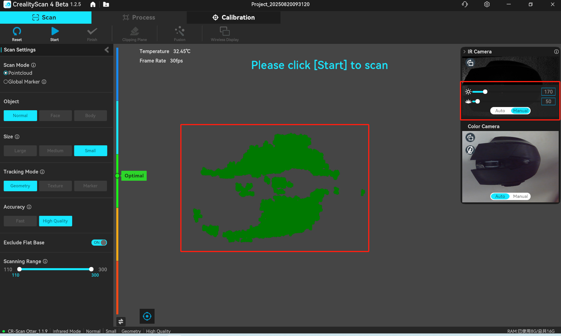
Before adjustment
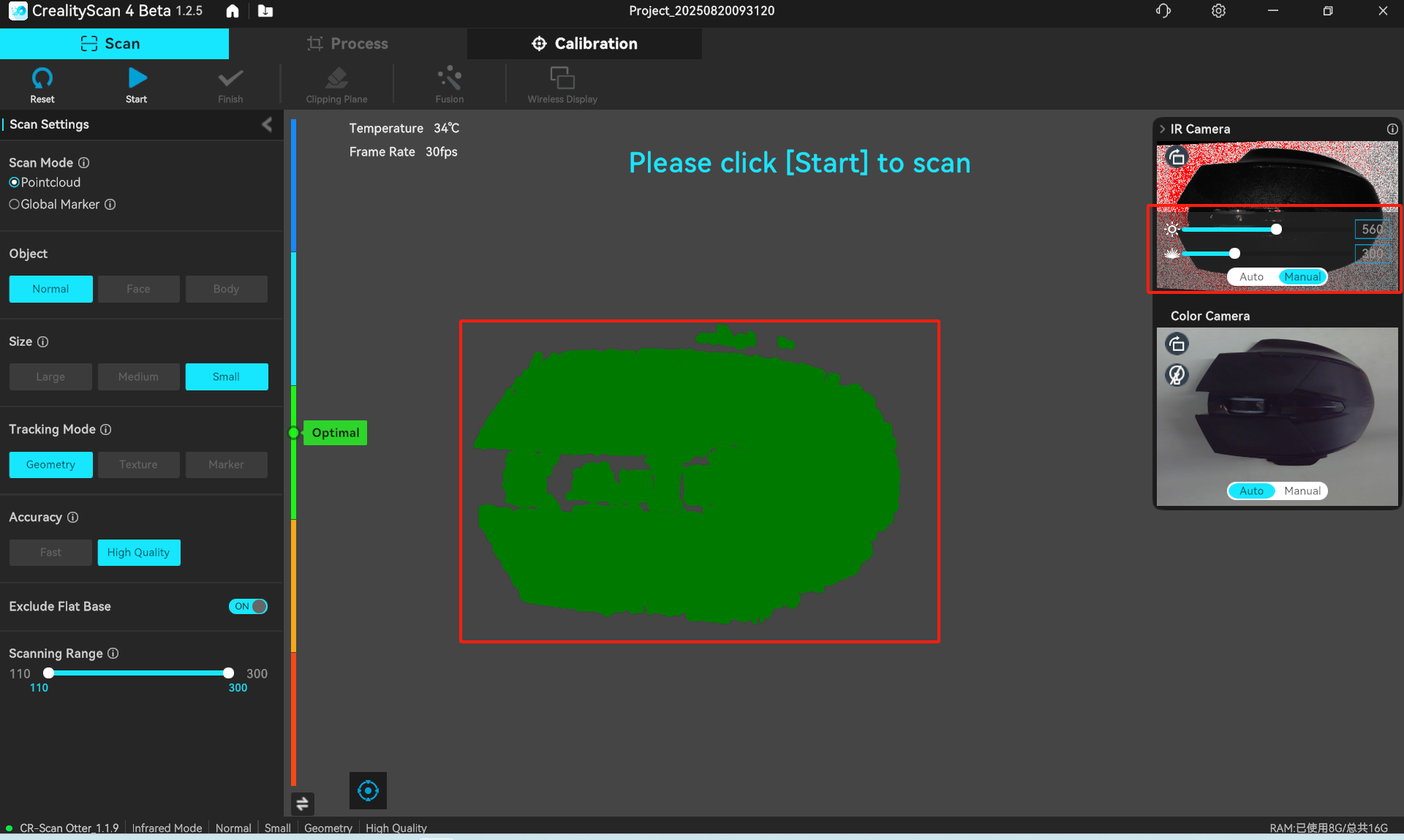
After adjustment
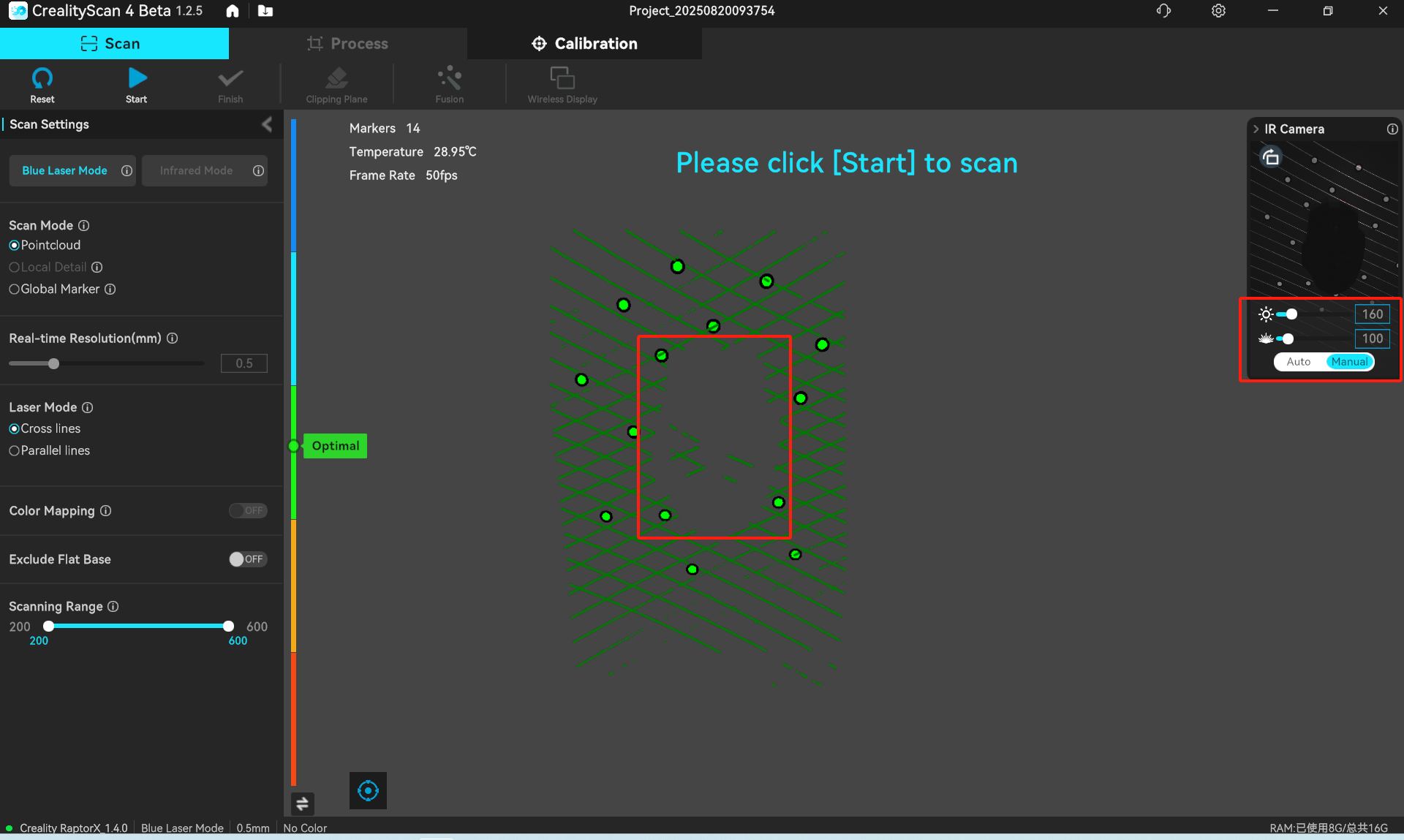
Before adjustment
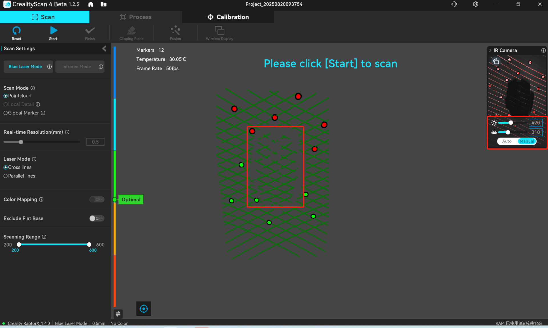
After adjustment
¶ Holes or Missing Data in the Scan
Solutions:
- Scan missing areas from different angles. Change the relative position and angle between the scanner and the object to capture more viewing angles.
.png)
- Deep holes/slits – the scanner can only capture surface data and cannot reach internal structures. For deep holes, grooves, or slits, use a model equipped with single-line scanning mode (e.g., Sermoon series, capable of up to 1:6 depth‑to‑diameter ratio).
- If data cannot be captured due to occlusion and angle adjustments do not help, the missing parts can be repaired through software hole‑filling or re-modeling.