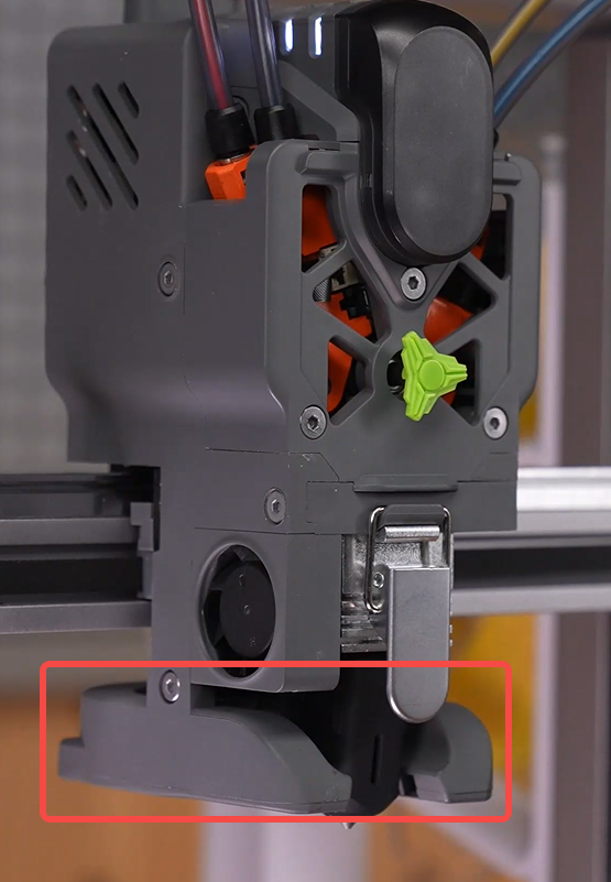
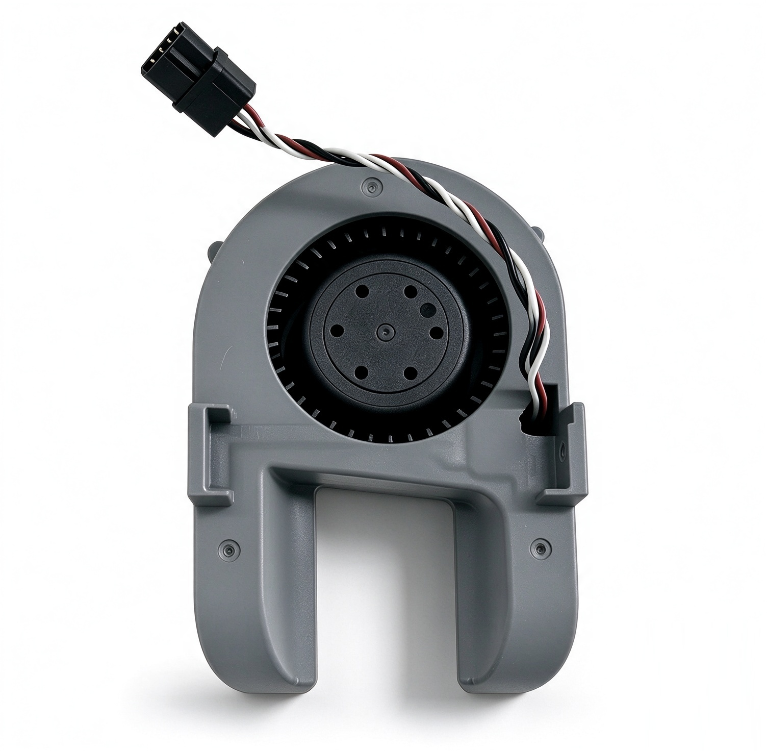
Replace the model cooling fan if any of the following symptoms occur:
Unusual noise (scraping, whining, rattling, etc.) during fan operation, which remains even after clearing filament wrapped around the fan.
Fan malfunction: fails to start upon power-up, unstable rotation speed, erratic start-stop behavior, or cannot reach the target speed during fan testing.
Damaged fan blades or seized bearing, so the fan cannot rotate normally.
Note: The model cooling fan dissipates heat for the printed part during printing. Fan failure may cause print defects such as part warping, poor interlayer adhesion, and print deformation.
Before servicing the printer or its toolhead cables, turn off the printer and unplug the power cord to prevent short circuits, equipment damage, and electric shock.
Allow the hotend and heated bed to cool to room temperature before maintenance or troubleshooting. Do not touch hot components with bare hands. If a separate procedure requires working on hot components, wear heat-resistant gloves to prevent burns.
If you have questions about this operation guide, please submit a ticket on the Creality Cloud App. We will offer technical support promptly.
1. Complete the filament unloading and cutting procedure for all loaded channels on the current spool holder. See the Filament Loading and Unloading Guide for details.
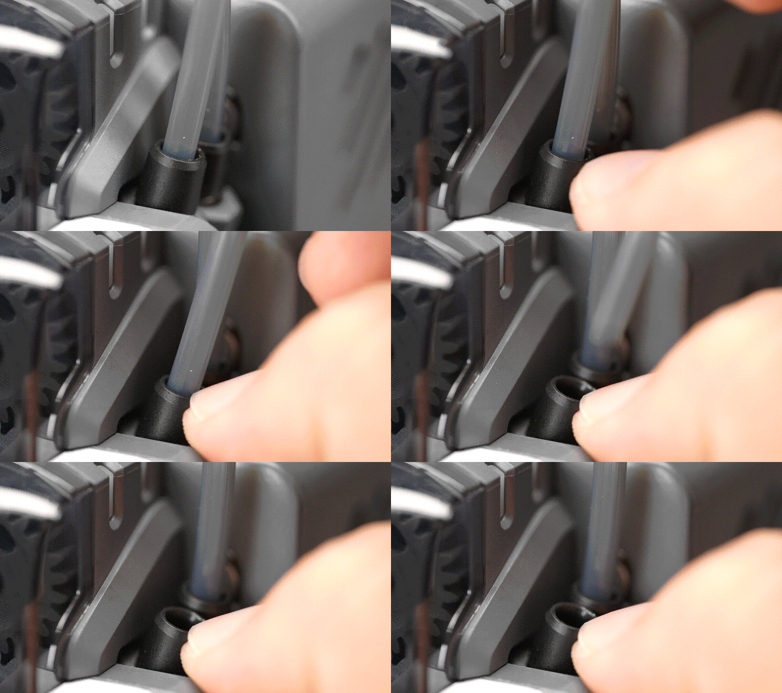
2. Press the release collar on the tube fitting and pull the PTFE tube upward to remove it.
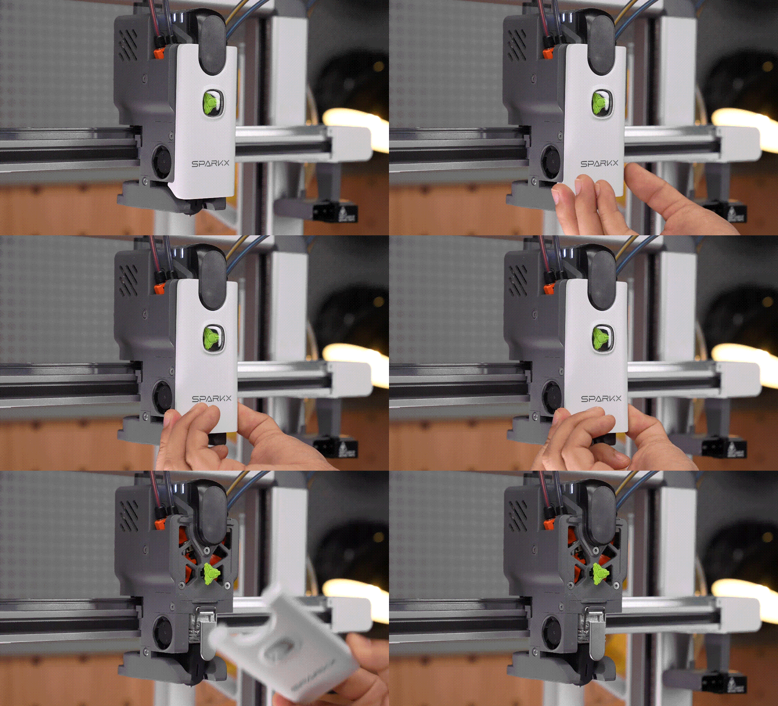
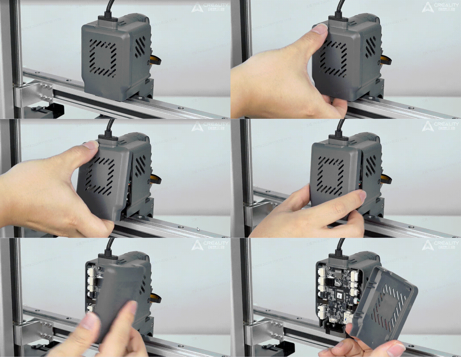
Press both sides of the toolhead front cover to release it, then remove the cover. Keep your fingers clear of the hotend cooling fans on either side. The release points are shown below.
2. Check for filament residue that has melted and solidified around the nozzle.
If residue is present, heat the hotend to 230 °C. Use a cardboard piece, or grip an alcohol-moistened kitchen paper towel with pliers to gently wipe off surface filament residue.
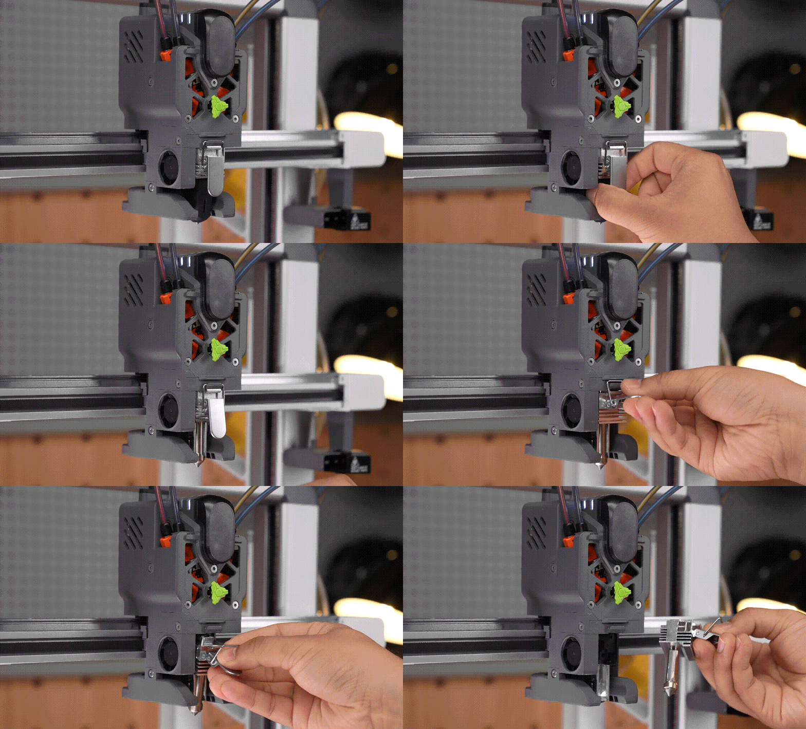
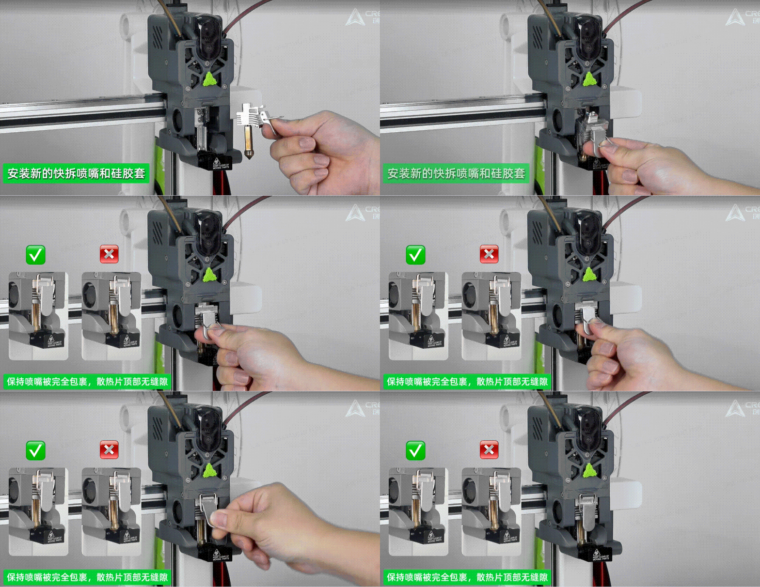
3. Release the hotend retaining clip and push it upward to open a gap between the hotend and the cutter assembly.
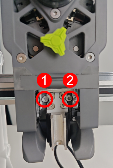
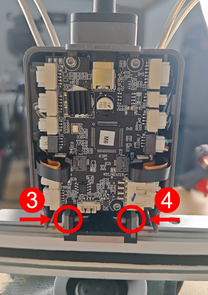
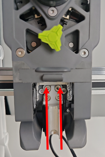
Support the toolhead. Use a 2.0 mm hex key to remove the four retaining screws, two on the front and two on the rear of the toolhead. The toolhead can then be removed from the X-axis carriage. The four screws are shown in the figure below.
Note: Do not pull on the connected cables while removing the toolhead.
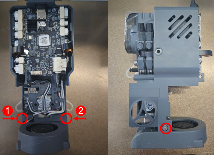
1. Use a 2.0 mm hex key to remove the two retaining screws on the left and right, then take out the model cooling fan assembly downward.
Note: The screws to be removed are shown in the figure below.
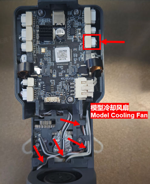
2. On the TH main board, press the latch and slide it to the right, then pull out the model fan terminal. Remove the model fan cable following the position shown in the figure below.
Install the model cooling fan assembly in the same orientation as it was removed. The air inlet faces upward, and the air outlet faces toward the nozzle and printed part.
Align the screw holes and reinstall the two retaining screws on the left and right with a 2.0 mm hex key.
Tighten the screws with moderate torque. Do not over-tighten to prevent thread stripping.
Align the fan cable connector with the matching socket on the TH board. Check its orientation, then insert it fully until the latch engages. Make sure the connection is secure.
Installation Notes:
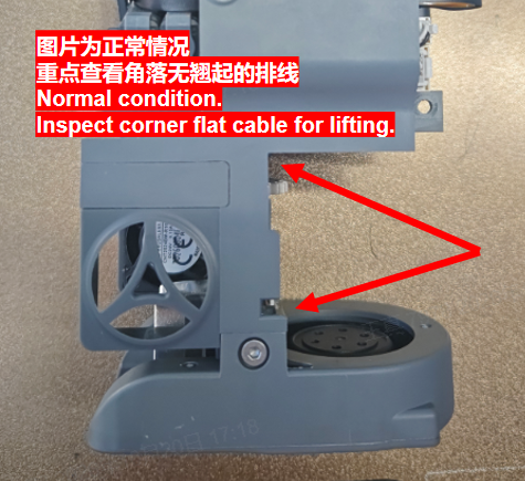
Route the cable without lifting or curling. Seat it fully into the cable channel per the reference diagram and avoid pinching the cable.
¶ 1. Reset the Cutter Mechanism and Reinstall the Toolhead
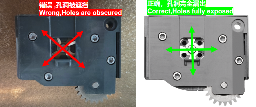
1. Check whether the four cutting edges of the cutter are in diagonal alignment. If misaligned, manually rotate the gear behind the cutter to reset it.
Tip:
Before mounting the toolhead, you may remove the hotend and inspect the reset status of the cutter cutting edges through the viewing opening shown in the figure.
2. Push the cutter rack fully behind the cutter gear.
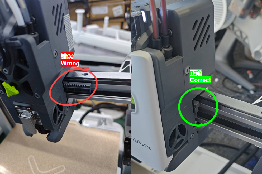
3. Mount the toolhead onto the X-axis carriage. Use a 2.0 mm hex key to reinstall the four retaining screws: two on the front and two on the rear.
Reinstall the hotend following the i8 Hotend and Sock Replacement Guide. Check that its filament inlet aligns with the cutter opening and that the metal spring clip is securely locked, then refit the silicone sock.
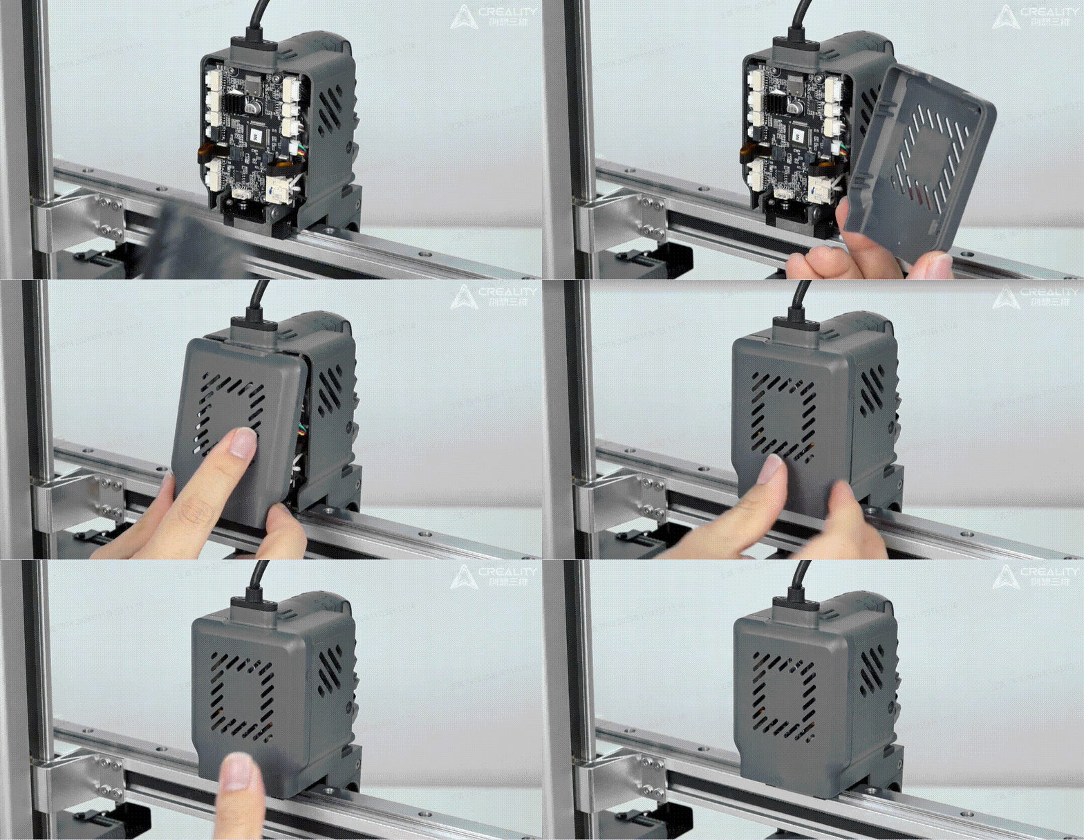
Make sure the rear cover is correctly installed and secure. Align the clips at the top of the front cover and gently press the cover into place until they engage. Check that the cover is secure.
After reassembly is complete, reconnect the power cord and turn on the printer.
Use the printer's fan controls to command the model cooling fan to run. Check that it starts normally.
Test the fan at low and high speed settings. Check that it responds to changes without unusual noise or stalling.
Check for excessive vibration.
Run a short test print with model cooling enabled. Check that the fan operates as commanded during printing.
If the fan does not run, makes unusual noise, or runs at an unexpected speed, turn off the printer, unplug the power cord, and allow hot components to cool before checking the connector, cable routing, and mounting screws.