¶ Operation Video
i7 Series Toolhead Board (Hotend Board) Replacement Guide
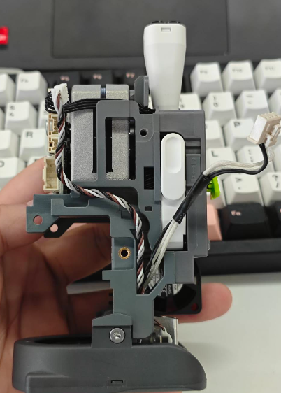
¶ i7 Toolhead Board
The control board for the toolhead, responsible for processing print-related commands.
¶ When to Replace
Replace the i7 Toolhead Board when the board is damaged, communication is abnormal, or related components connected to the Toolhead fail to function properly.
¶ Required Tools
Hex wrench (H2.0)
Tweezers
¶ Procedure
¶ Safety Preparation
For your personal safety and to avoid machine damage, please turn off the power and unplug the Power cable before starting the replacement. Do not operate while powered on.
¶ Remove the Old Toolhead Board
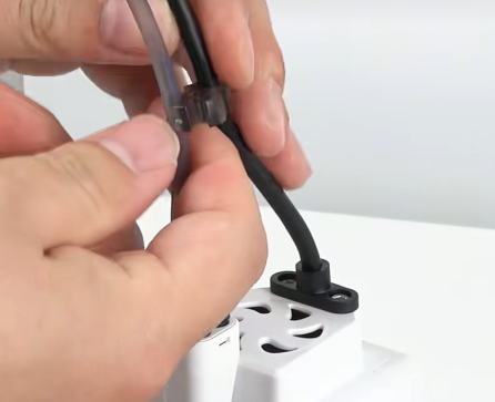
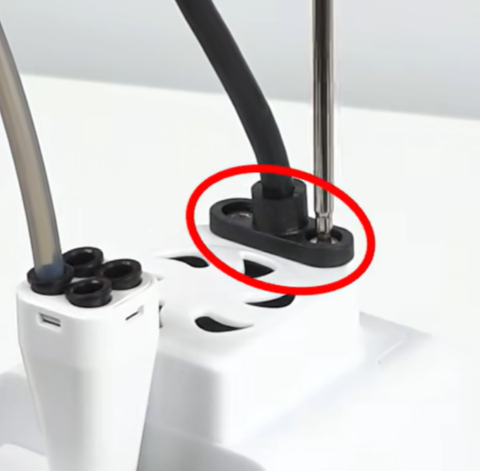
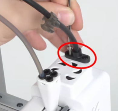
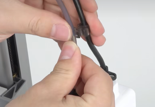
¶ Remove the Toolhead Cable
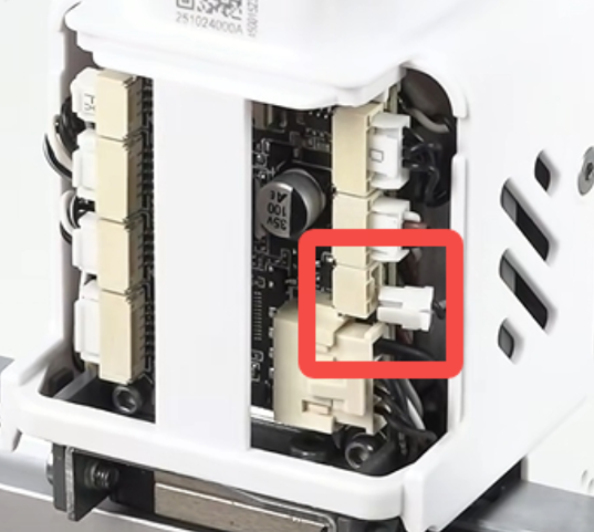
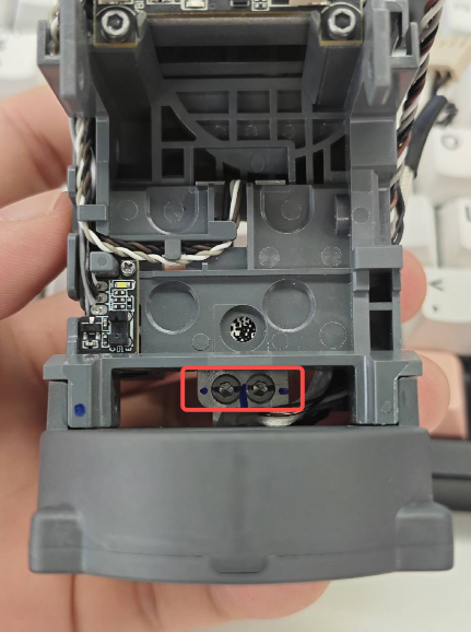
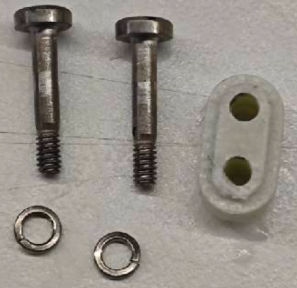
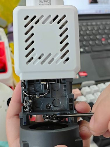
Remove the clip securing the PTFE tube and Toolhead Cable. Use the Hex wrench to remove the two fixing screws of the Toolhead Cable, then unplug the cable.
 |
 |
 |
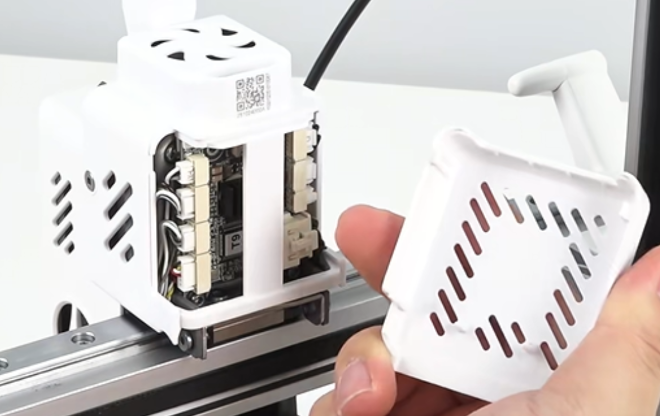
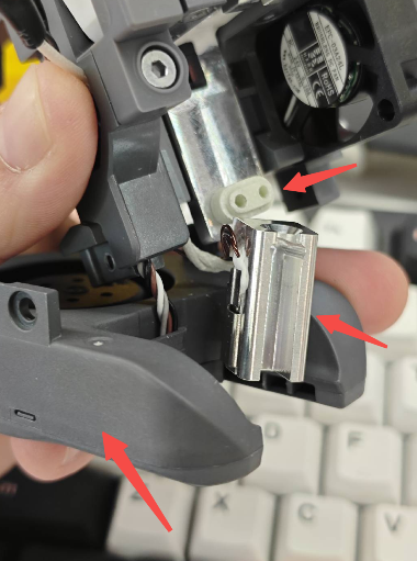
¶ Remove the Extruder Cooling Fan
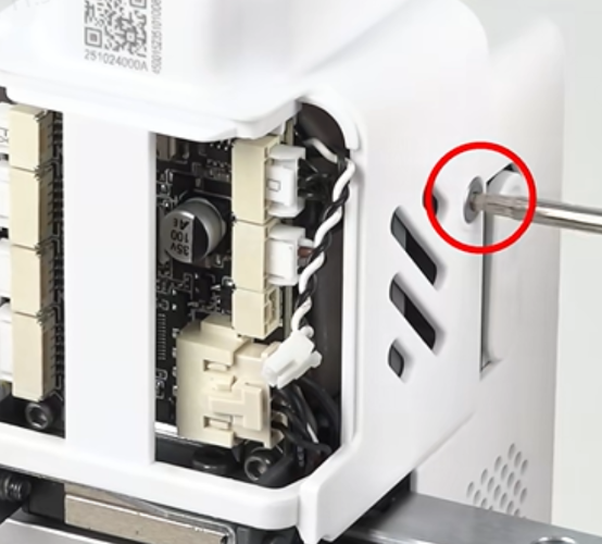
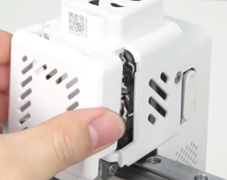
Remove the i7 Toolhead Back Cover, then unplug the Extruder Cooling Fan connector. Tweezers can be used for assistance.
 |
 |
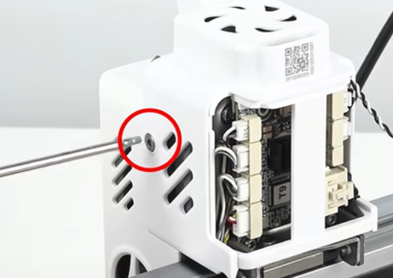
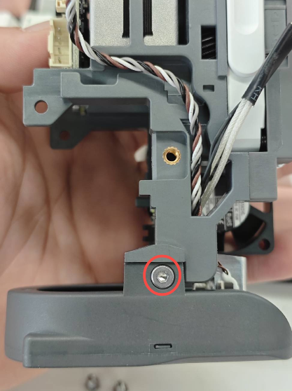
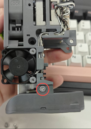
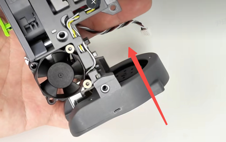
Unscrew the left and right screws securing the rear extruder housing, then remove the rear housing.
 |
 |
 |
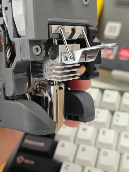
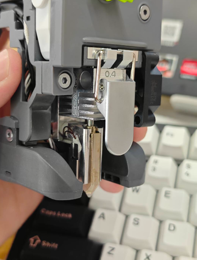
¶ Remove the Old Toolhead Board
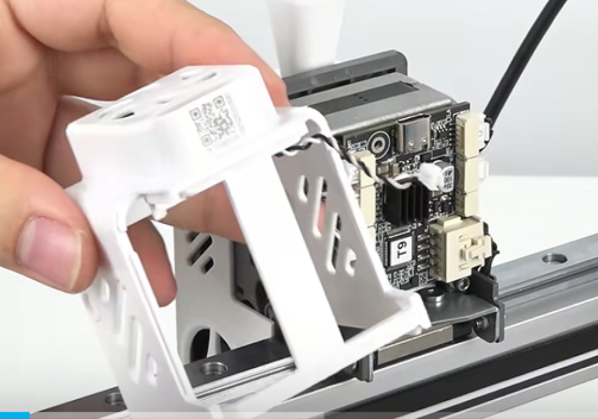
Disconnect all wire terminals from the i7 Toolhead Board, then remove the two fixing screws to take out the old board.
 |
 |
 |
¶ Install the New Toolhead Board
Prepare the new i7 Toolhead Board, install it into the original position, and tighten the two fixing screws.
Note: Do not overtighten the screws, as this may damage the i7 Toolhead Board or strip the screw threads.
 |
 |
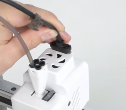
Reconnect all wire terminals except the Extruder Cooling Fan connector. Make sure each connector is inserted into the correct port. Reinstall the rear extruder housing and reconnect the Extruder Cooling Fan connector.
 |
 |
 |
Tighten the two fixing screws and reinstall the i7 Toolhead Back Cover.
 |
 |
 |
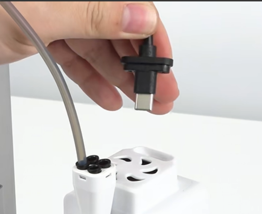
Reconnect the Toolhead Cable and tighten the two fixing screws. Finally, secure the PTFE tube back into the cable clip.
 |
 |
 |