¶ Toolhead Manifold Assembly
The Toolhead Manifold is used to merge multiple filament channels, enabling unified management and distribution of up to four filament paths. It is a critical component for multi-color printing on the SPARKX i7.
¶ Required Tools
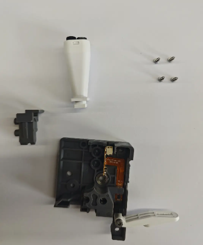
Toolhead Manifold Assembly
H2.0 Hex wrench
Tweezers
¶ Procedure
¶ Safety Preparation
Turn off the power and unplug the power cable. Do not operate while powered on
Ensure the Hotend and Heated Bed have completely cooled down before operation to avoid burns
¶ Remove the Old Manifold Assembly
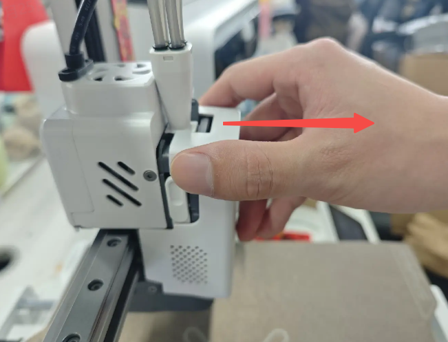
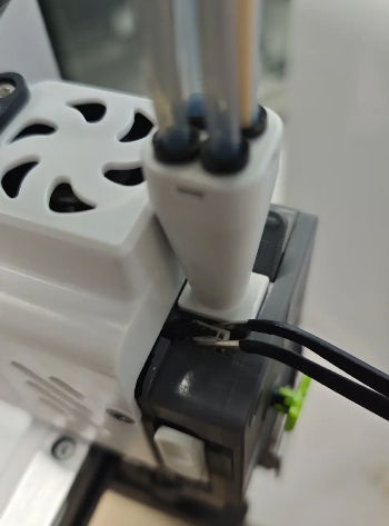
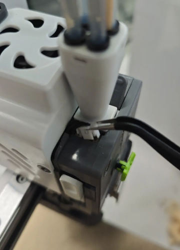
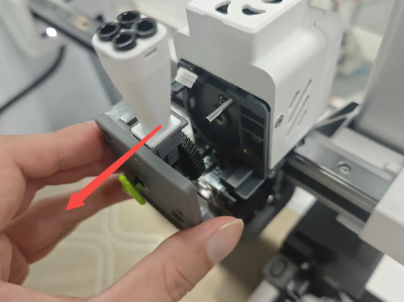
Remove the Extruder Front Cover, and use tweezers to unplug the Filament Sensor connector
 |
 |
 |
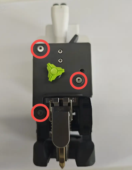
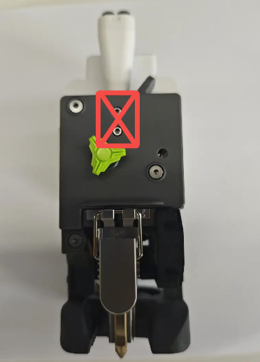
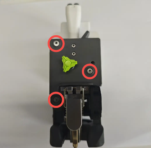
Use an H2.0 Hex wrench to remove the three screws of the Extruder Front Housing Assembly ⚠️ Do NOT remove the two manifold fixing screws at this step
 |
 |
 |
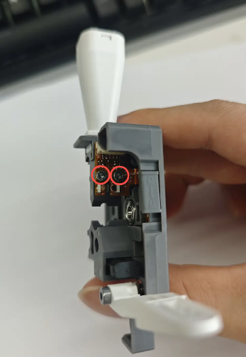
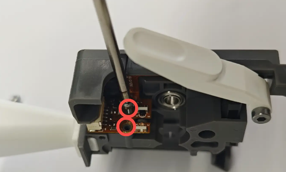
Remove the Extruder Front Housing Assembly, then from the side, use an H2.0 Hex wrench to remove the two screws of the Filament Sensor Board
 |
 |
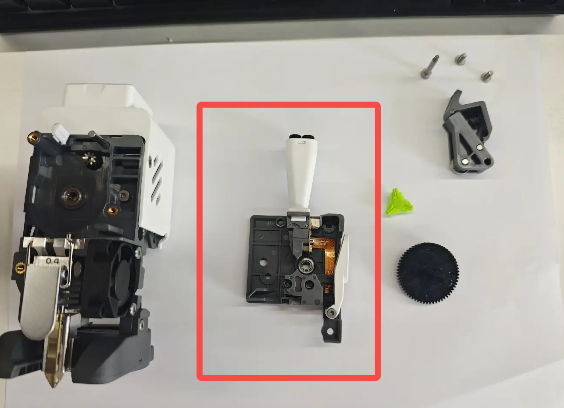
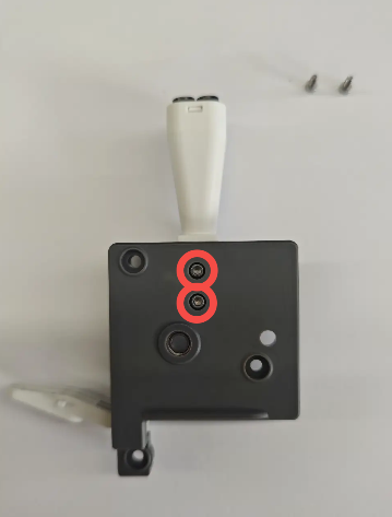
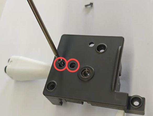
Remove the upper and lower filament guide parts, then from the front side of the housing, remove the two fixing screws of the Toolhead Manifold Assembly and take out the manifold
 |
 |
¶ Install the New Manifold Assembly
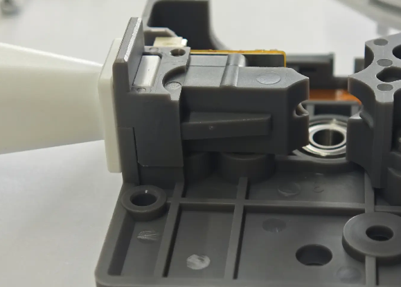
Prepare the new Toolhead Manifold Assembly and install it into the corresponding slot of the Extruder Front Housing Assembly. Reinstall the upper and lower filament guide parts, ensuring correct positioning of the Filament Sensor Board
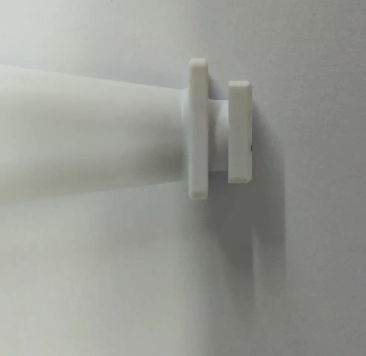
Note: The manifold has a directional requirement:
The longer flange side should face the Extruder Front Housing Assembly; The shorter side should face the lower filament guide part. After installation, confirm that the lower part is fully secured
 |
 |
From the front side, tighten the two fixing screws of the Toolhead Manifold Assembly
From the side, reinstall and tighten the two screws of the Filament Sensor Board
Reinstall the Extruder Front Housing Assembly onto the Toolhead, tighten the three screws, and reconnect the Filament Sensor
 |
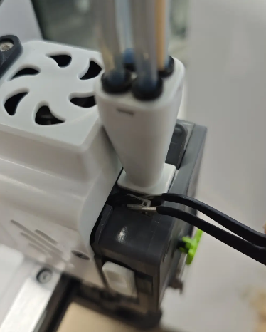 |
Reinstall the PTFE tube and the Extruder Front Cover