The i7 Autofill Combo is available in two packaging versions. Please select the corresponding unboxing guide based on your package. This section introduces the unboxing steps for the disassembled version of the i7 Autofill Combo. For the fully assembled version, please refer to: i7 Unbox Guide (Assembled Version)
¶ Video Tutorial
¶ Unboxing and Removing Accessories
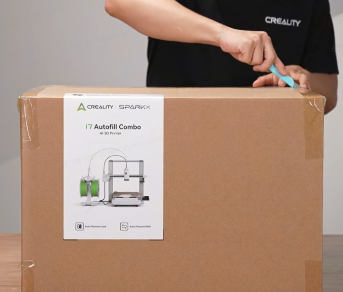
¶ Open the outer box
Use scissors to cut the tape on the top of the box and open the outer box.
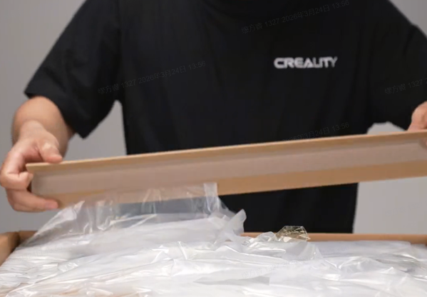
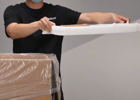
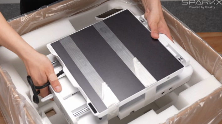
¶ Gantry
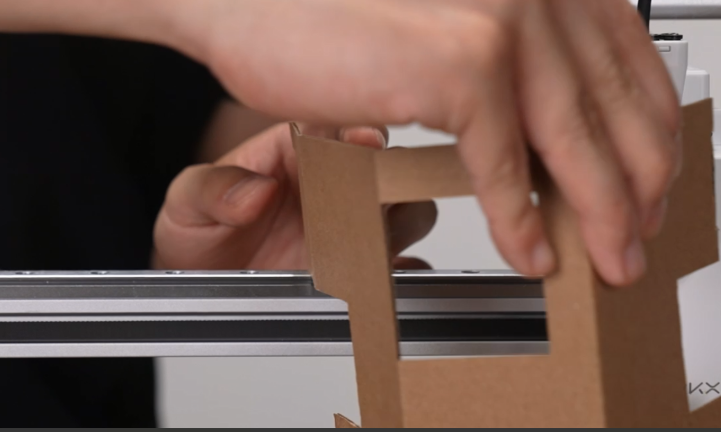
Remove the four protective cardboard pieces, open the moisture-proof bag, and take out all the top foam and related accessories.
 |
 |
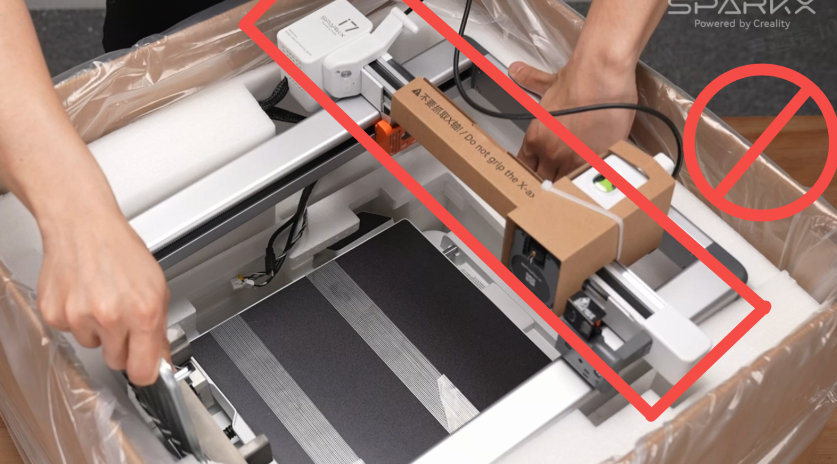
Hold the top of the Gantry, lift it out, and place it on the table.
Note: Do not hold the X-axis Assembly when removing the gantry!
¶ Base
Remove the foam on the base, and lift the Base out with both hands.
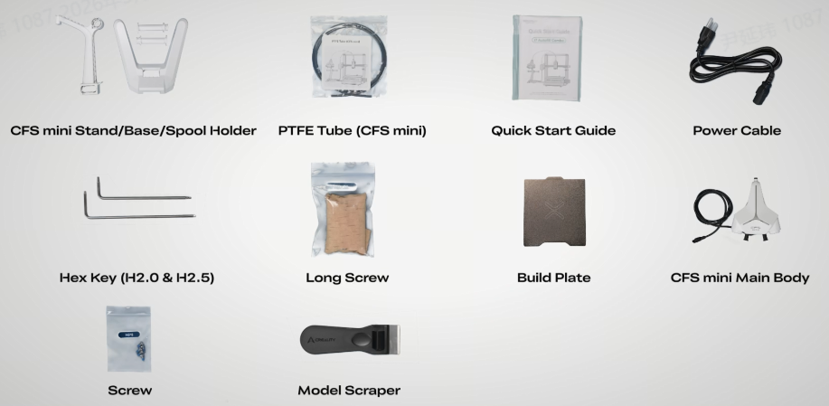
¶ Other Accessories
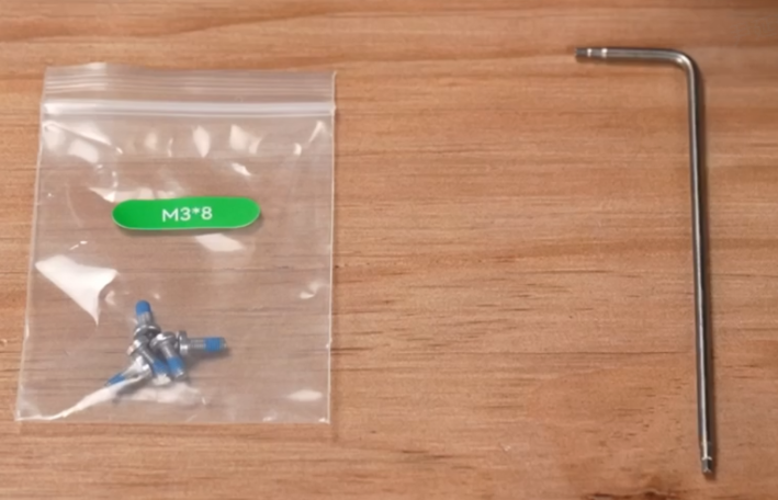
Accessory list included in the package.
¶ Install the i7 and Spool Holder
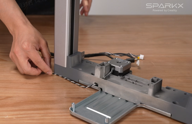
¶ Install the Gantry and Base
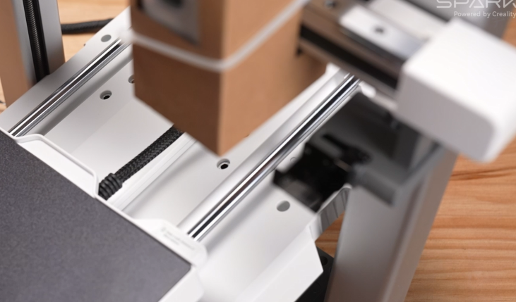
Place the Gantry upright on the table. Make sure to move the bottom cables aside to avoid pinching them when installing the base.
Remove all tape from the base. Tilt the base at a 45° angle and insert it into the gantry. Align the grooves on both sides, then lower it into place and ensure it is properly installed.
 |
 |
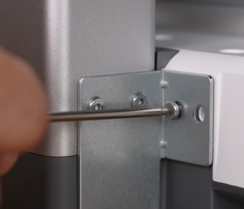
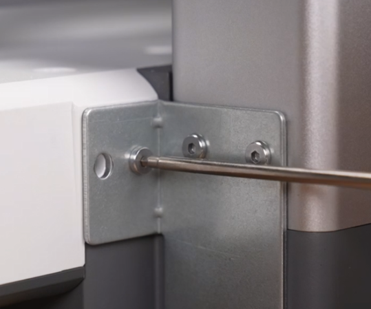
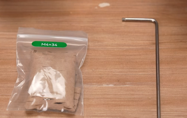
Take the shorter screws from the accessory kit and use a Hex wrench (H2.0) to fasten both sides of the gantry.
 |
 |
 |
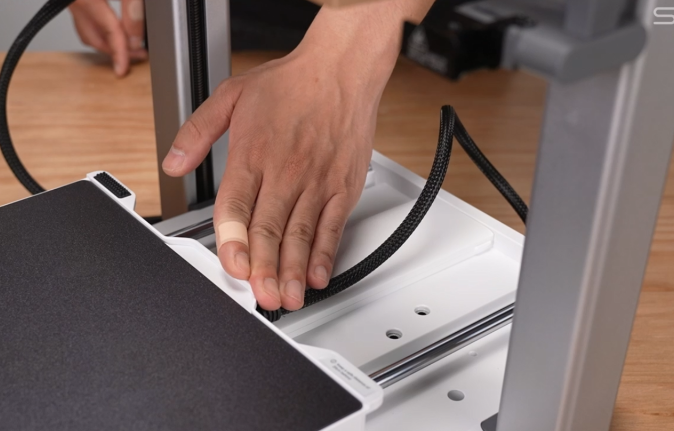
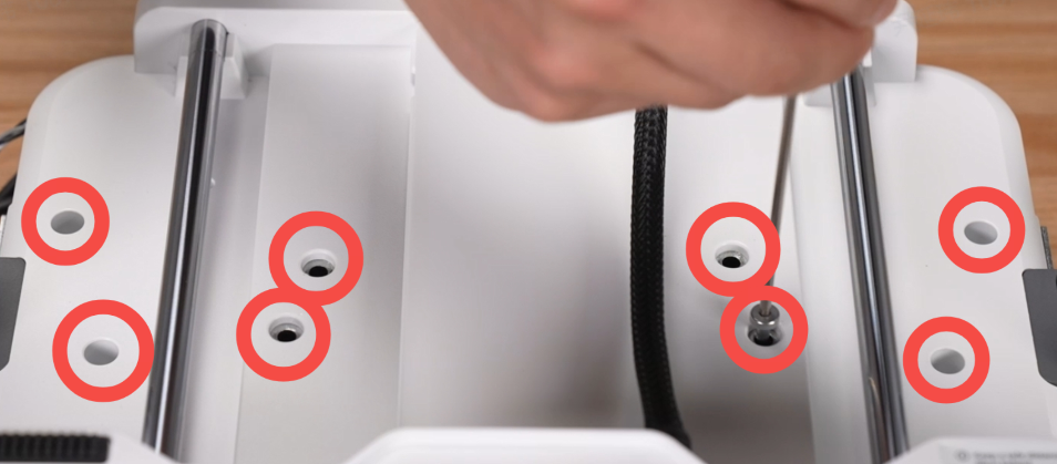
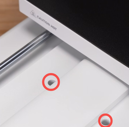
Move the Heated Bed to the front of the machine. Use a Hex wrench (H2.5) to install the longer screws into the eight screw holes as shown. Then move the Heated Bed to the rear and install the remaining two screws.
 |
 |
 |
 |
 |
|
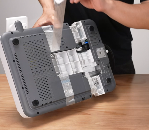
¶ Connect the Toolhead Cable
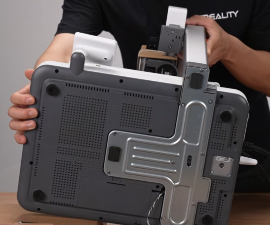
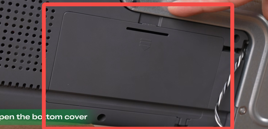
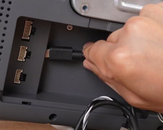
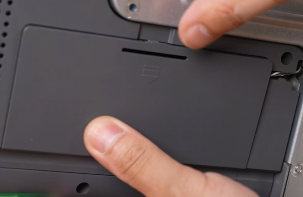
Lay the machine on its left side to expose the bottom. Open the Base Cover, and connect each terminal (each connector only fits its matching port—do not force it).
 |
 |
 |
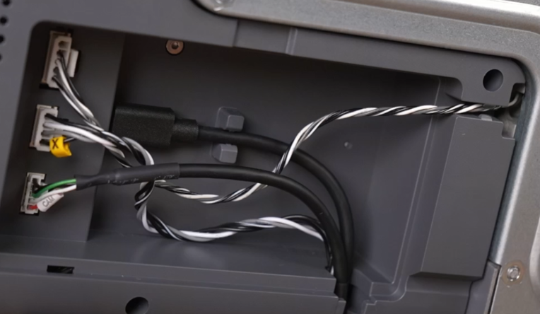 |
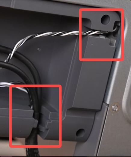
After connecting, route the cables into the cable slots, close the Base Cover, and return the machine to its upright position.
 |
 |
¶ Assemble the Spool Holder and Install CFS Mini
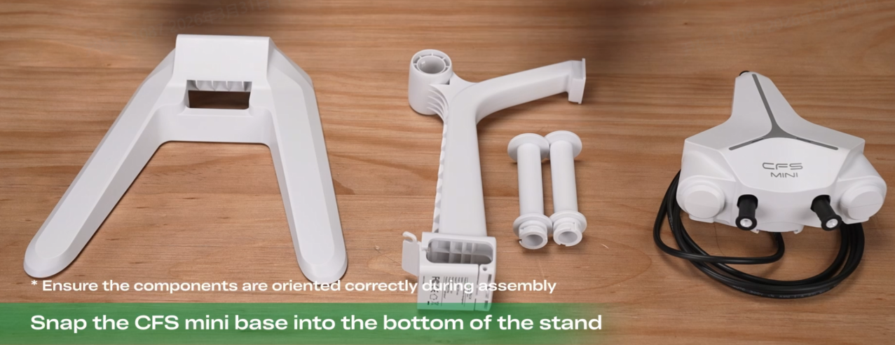
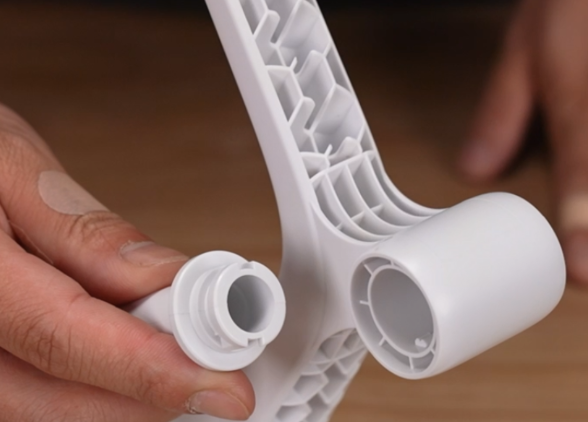
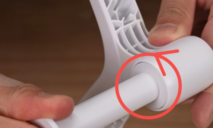
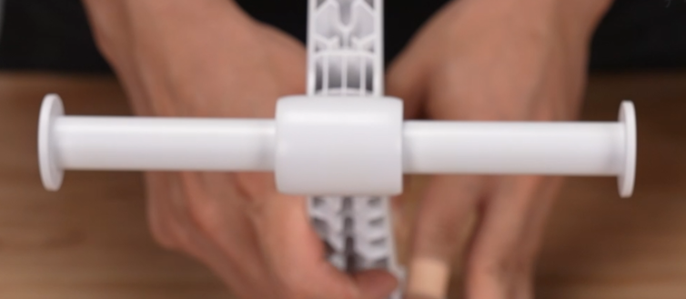
Take out the Spool Holder components. Align the two spool rollers with the corresponding slots and rotate them into place.
 |
 |
 |
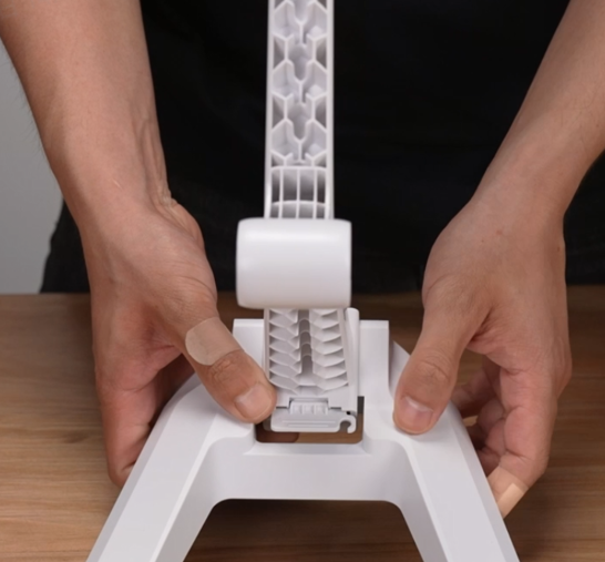
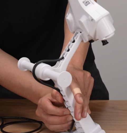
Install the base of the Spool Holder and secure the clips (note the installation direction). Then take the CFS mini and slide it into the holder until fixed.
 |
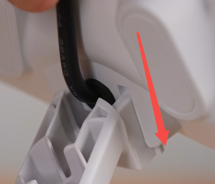 |
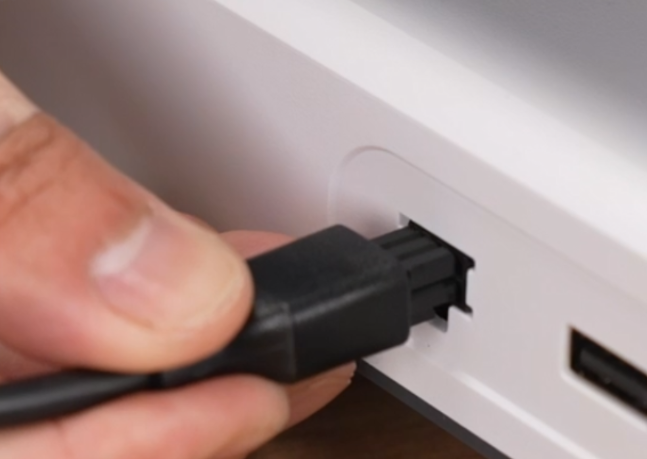
Use the cable slot on the holder to secure the communication cable, and connect it to the 485 port on the left side of the printer.
 |
 |
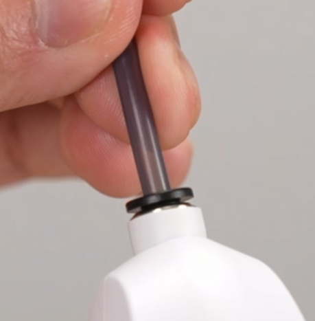
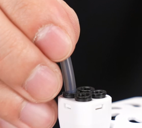
Connect the PTFE tube
 |
 |
¶ Pre-Power-On Preparation
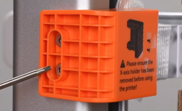
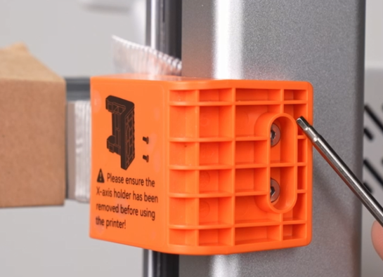
¶ Unlock the X-axis
Use a Hex wrench (H2.0) to remove the four screws on the X-axis Transport Bracket, then remove the bracket and tape.
 |
 |
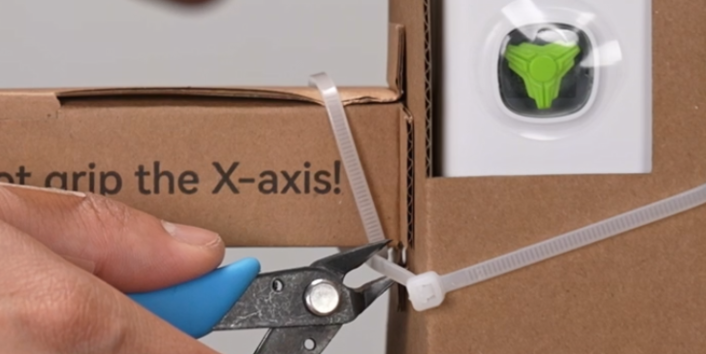
Cut off the zip ties on the X-axis Assembly and remove the protective cardboard.
 |
 |
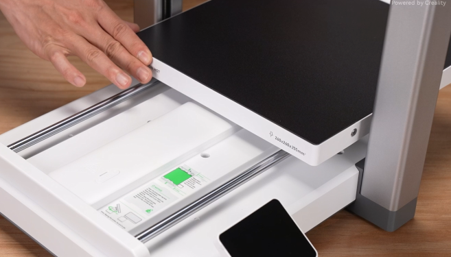
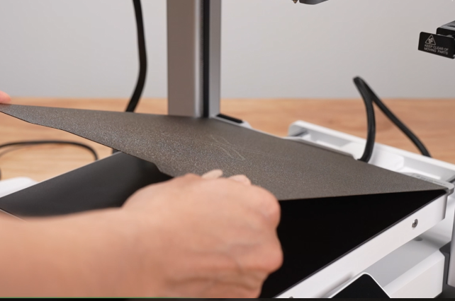
¶ Place the Print plate
Take out the i7 Dual-Texture PEI Plate and align it with the grooves on the Heated Bed.
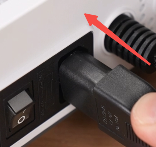
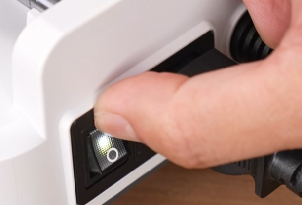
¶ Connect the Power cable
Take it out and connect the Power cable, then turn on the switch.
 |
 |
¶ Power-On Self-Check
Follow the on-screen instructions to complete the startup guide and self-check.
After the self-check is completed, you can start using the printer. For first-time use, please refer to: i7 First Print Guide (Using CFS mini) (SPARKX i7 Using CFS mini: Assemble cfs mini + load filament + print local files)