¶ About Calibration
When using an FDM 3D printer for printing, it's essential to ensure that the machine's performance aligns with the characteristics of the filament to achieve optimal print results. To attain the best printing outcomes, it's necessary to observe various factors such as temperature, flow rate, and pressure advance of the filament during the printing process. By scientifically and meticulously adjusting printing parameters, the perfect synergy between the printer and filament can be achieved, resulting in the creation of an ideal printed model.
¶ Calibration Dimensions
We know that the printing effect of the consumables will be different under different nozzle temperatures, different flow states, and different pressure advances.
Then, the process of observing and comparing the actual printing effect of consumables on these different surfaces is the process of consumables calibration. The different faces represent calibration dimensions.
- Temperature
Under the premise of different printers and different consumables, by adjusting the temperature of the consumables, select the temperature of the consumables with the best printing effect. - Flow rate
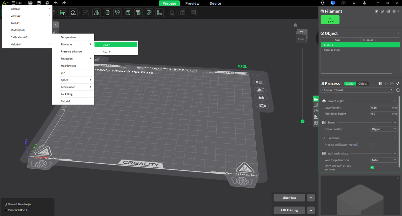
1)Step 1
The broad and common flow ranges are listed, and their respective printing effects are integrated to prepare for further comparison and optimization.
2) Step 2
Adjust and narrow the flow fine-tuning range more carefully, and filter out the flow adjustment difference for the best printing effect. - Pressure advance
Comparing the printing effects of different pressure advance scenes to adjust the relevant consumable application parameters. - Max volume flow (velocity)
- VFA(振纹)
¶ How to Calibrate
¶ Temperature
By printing multiple layers of the same structural model, each layer is printed using a different nozzle temperature. Compare the printing effects of each layer to determine the optimal filament temperature.
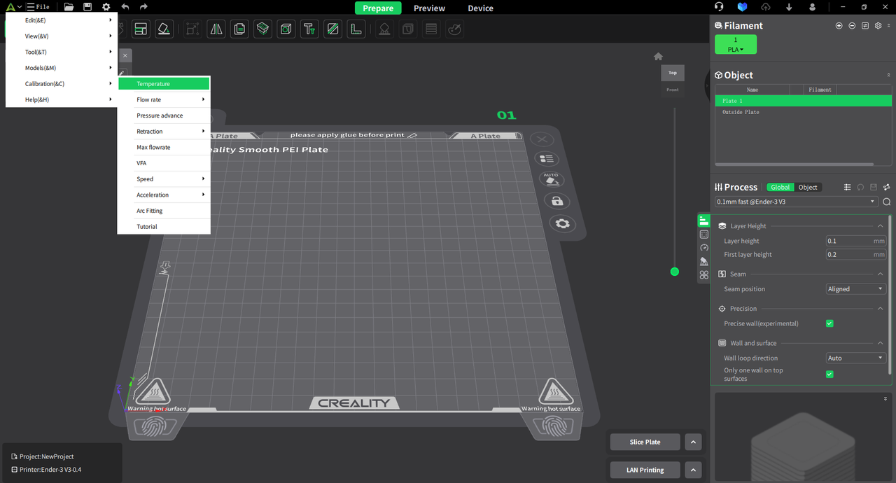
¶ Entrance for temperature calibration
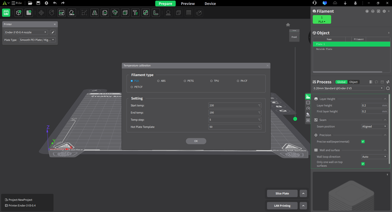
¶ Select the filament currently used on the printer, set the parameters (displayed as PLA), and click "OK"
- Set the recommended temperature range for the filament.
- Set the temperature increment for each layer: temp step.
- Set the recommended hot plate template for the filament.
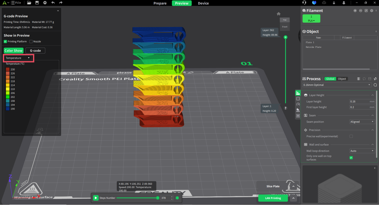
¶ View preview effect
After slicing is completed, switch the display information to temperature to view temperature differences.
¶ Analyze the printing results and adjust relevant parameters
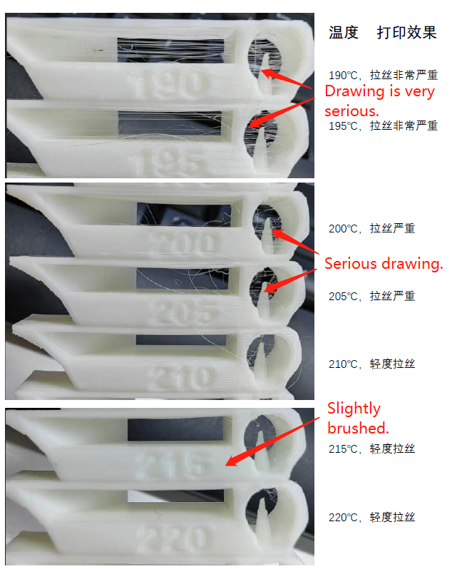
1. Result analysis
Through this temperature calibration, we can ultimately analyze from the actual printed results that when the filament temperature is 220°C, the stringing issue is minimized, resulting in the smoothest printing effect. Therefore, through the filament temperature calibration function, we determine the optimal printing temperature for this PLA filament to be 220°C.
2. Parameter adjustment
Enter the filament parameter management to set the parameters and save as a new user preset.
¶ Flow rate
By printing models with different flow rates, we observe the optimal flow rate of the filament on the printer to achieve the best printing effect. This process is divided into two steps: coarse flow adjustment and fine flow adjustment. In the coarse flow adjustment stage, we obtain an approximate flow rate range; while in the fine flow adjustment stage, we determine the precise flow rate value based on the coarse adjustment results. The following provides detailed explanations of these two steps:
¶ Step 1
Before flow rate adjustment, you need to select the consumable filament parameters. It is recommended to refer to the official consumables of the same type. For example, you can choose CR - Silk for third - party silk consumables and Hyper PLA for high - speed PLA. This can minimize other parameters that need to be adjusted.
Take the Generic PLA as the reference consumable parameters for demonstration. As shown in the following figure, you need to change the flow ratio in the reference consumable parameters to 1, change the printing temperature to the optimal printing temperature of the test consumable, and then save it as a user preset.

¶ Entrance for step 1
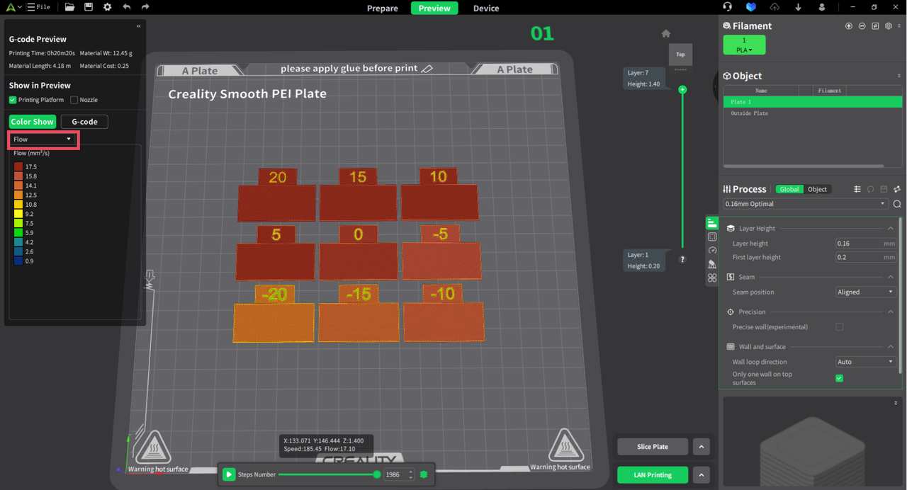
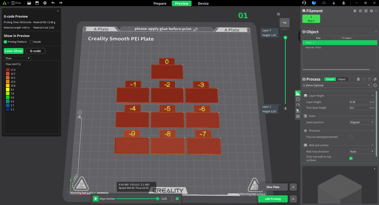
¶ The system automatically generates models with different flow rates (currently in the range of -20 to 20), which are arranged sequentially on the bottom plate.
After slicing, switch the display information to flow to observe the differences in flow rates. During the printing process, each block will use different flow rate parameters, with a total of 9 flow rate parameters: [-20, -15, -10, -5, 0, 5, 10, 15, 20]. Among these, a flow rate parameter of 0 represents 100% flow rate, a parameter of 20 indicates an increase in flow rate to 1.2 times the original value, while a parameter of -20 signifies a reduction in flow rate to 0.8 times the original value.
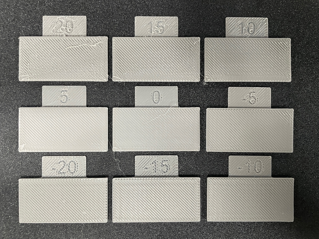
¶ Analyze the printing results
By observing the printing results, it can be found that there are many gaps between the top surface filling lines of the specimens with coarse - adjustment values of -5, -10, -15, and -20, which indicates that the flow ratio is too low. For the specimens with values of 20, 15, 10, and 5, the severe extrusion of the material between the top surface filling lines leads to a rough top surface, suggesting that the flow ratio is too high. In contrast, there are no gaps between the top - surface filling lines of the specimen with a value of 0, and the top surface is relatively smooth. Therefore, the result of the coarse-adjusted flow ratio is 1×(100% + 0%) = 1.
¶ Step 2
¶ Entrance for step 2
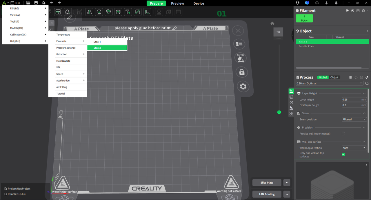
¶ Select the flow rate percentage difference that yields the best printing results in step 1.
Select the fine-tuning calibration method (using the test model with the best printing results obtained from the coarse adjustment, for example, 0%).
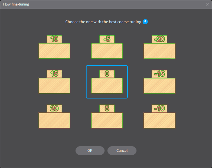
¶ Click OK to pop up a fine-tuning further filtering traffic panel (same as the coarse tuning process)
Similarly, a fine - tuning calibration test model will appear. Click "Send and Print", and then analyze the actual printing results.
¶ Analyze the printing results and adjust relevant parameters
1. Result analysis
Through the coarse and fine adjustments of the two-stage flow calibration, we obtain the following results: the step 1 value is 0%, and the step 2 value is - 2%. Therefore, the optimal flow rate for printing is 0.98.
*Formula: Optimum Flow Ratio =The flow ratio in the user preset before calibration.Step1 Flow Ratio * Step2 Flow Ratio=1×(100%+0%)×(100%-2%)=0.98
2. Parameter adjustment
Based on the final optimal flow percentage obtained, adjusting the internal printing parameters of the filament can achieve the goal of optimizing printing effects through filament flow calibration.

¶ Pressure advance
The klipper firmware optimizes the print quality at corners by introducing pressure compensation. The basic principle is to increase nozzle pressure during acceleration to extrude extra filament, and reduce nozzle pressure to retract filament during deceleration.
The parameter involved in the pressure compensation function is pressure_advance (subsequently referred to as PA). A larger PA value will cause overflow, and a smaller PA value will cause insufficient extrusion of consumables.
Therefore, there is an optimal PA value, and this parameter is related to the type of consumables, so it is highly recommended to re-measure the most appropriate PA value when changing the type of consumables. We provide two test methods, namely "PA tower" and "PA line".
When the "PA tower" test method is selected, by inputting the initial PA value, the end PA value, and the PA step distance, the slicing software will generate a cylindrical printing model with a pentagonal cross section. In the process of printing the model, the PA value will change linearly with the Z axis, that is, the PA value is equal to the starting PA value when printing the first layer, and the PA value is equal to the ending PA value when printing the last layer. After printing, observe and find the position with the best printing effect, measure its layer height.
According to the formula:PA=startPA+Z∗PAstep
Start PA: 0;
End PA: The test model has printed the PA of the last layer;
Calculate the optimal PA value, where Z is the layer height of the test model.
The following detailed steps explain the pressure advance calibration:
¶ Entrance for pressure advance calibration
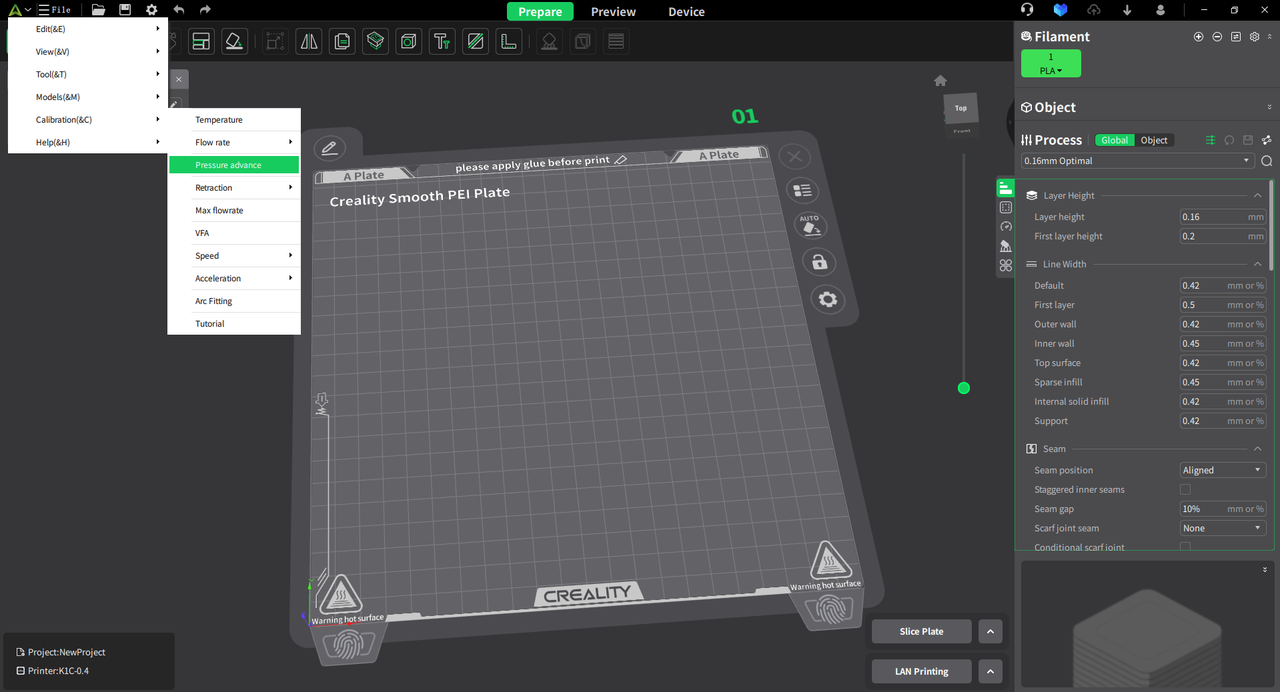
¶ Default PA tower test, set PA range, start calibration process
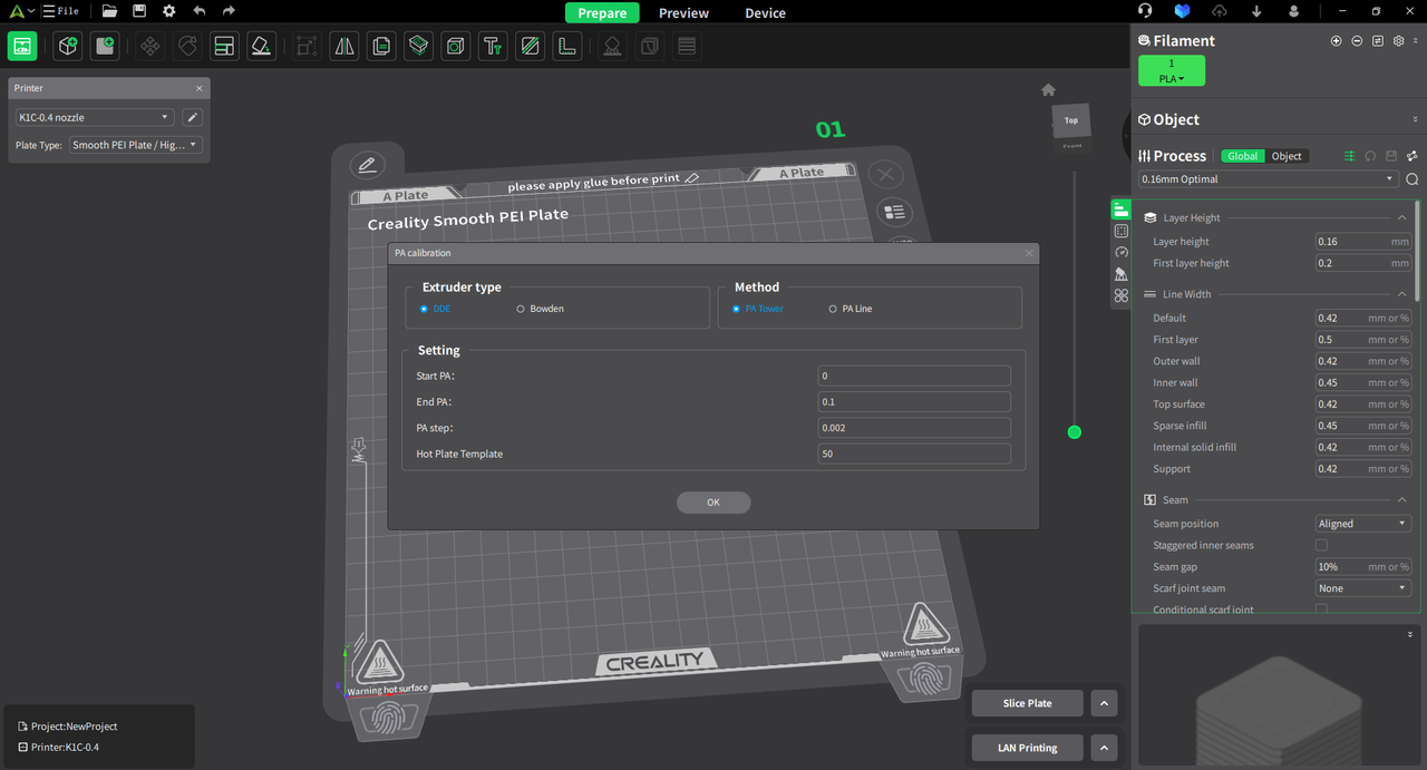
Set the PA range to compare the printing effect of different ranges.
¶ View preview effect
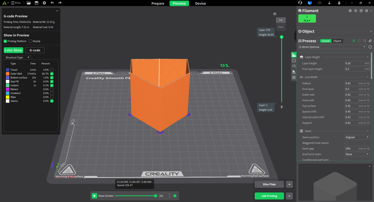
Pressure advance PA test model gcode.
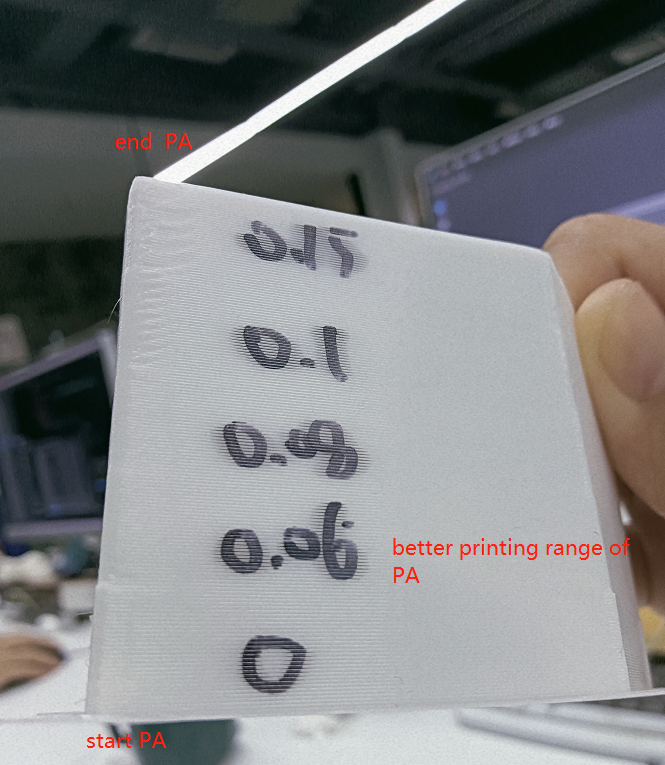
¶ Analyze the printing results and adjust relevant parameters
1. Result analysis
When calibrating and comparing the actual printing effects, we observed that the model's corner effect is optimal around a height of 30mm. As the height increases, the corner printing effect gradually deteriorates. Therefore, we determined that the current height of 30mm yields the best printing results.
Based on this conclusion, we can calculate PA.
According to the formula: PA = Start PA + Z * PA Step
Thus: PA = 0 + 30 * 0.002 = 0.06
2. Parameter adjustment
Use the calibrated optimal PA value to adjust the internal printing parameters of the filament.
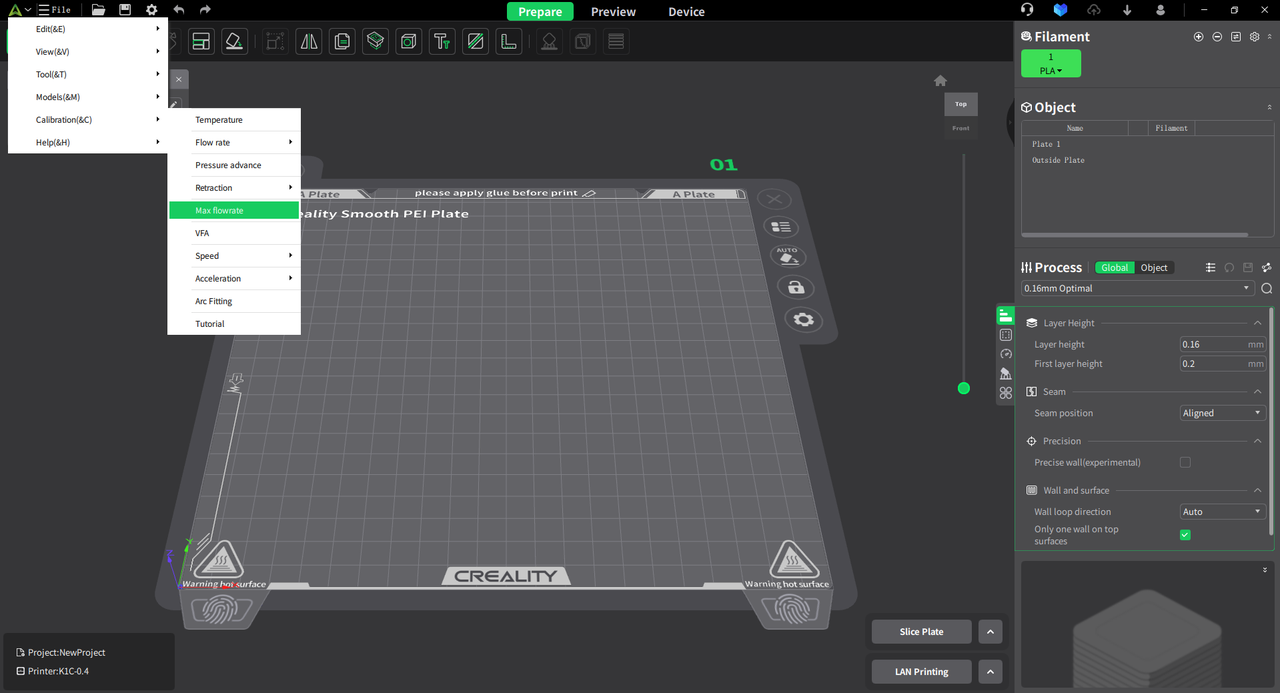
¶ Max volume flow
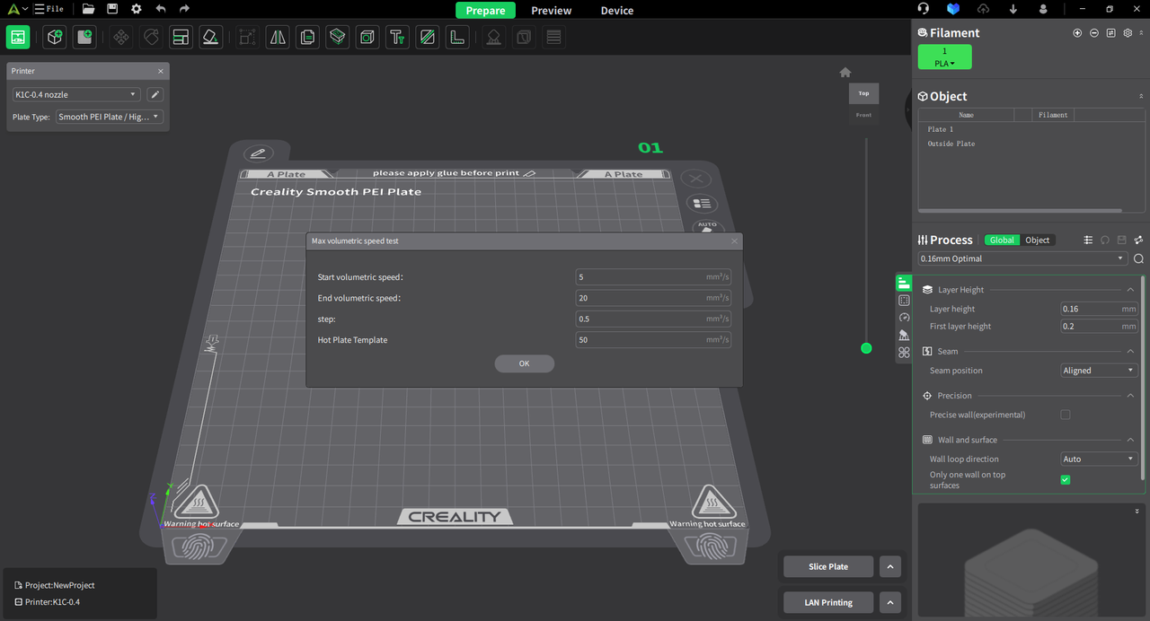
In the "Calibration" tab, select "Max Volume Flow." Enter three parameters: starting flow, ending flow, and flow increment. The slicing software will generate a printing test model. By default, the start volumetric speed is 5, the end volumetric speed is 20, and the step is 0.5.
¶ Entrance for max volume flow
¶ Max volume flow settings
¶ View preview effect
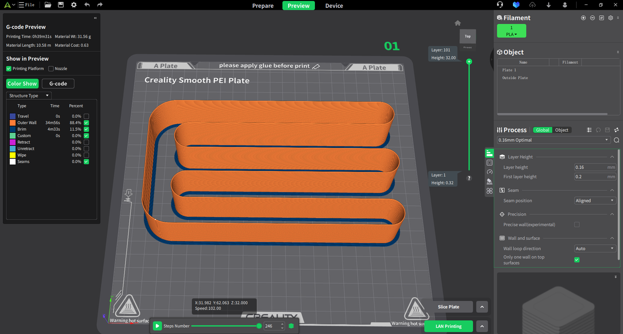
Max volume flow test model gcode.
¶ Analyze the printing results and adjust relevant parameters
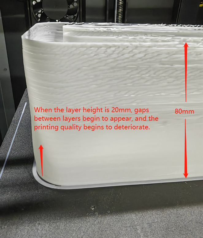
1. Result analysis
When calibrating and comparing the actual printing results, we observed that as the layer height approaches about 20mm, the printing quality gradually deteriorates with increasing height. Therefore, we conclude that the optimal layer height for printing is currently 20mm. Based on this conclusion, we can calculate the max volume flow.
According to the formula: Max volume flow = Starting volumetric speed + Observation height * step
That is: Max volume flow = 5 + 20mm * 0.5 = 15
2. Parameter adjustment
Modify the max volume flow(speed) parameter value in filament management .
¶ VFA
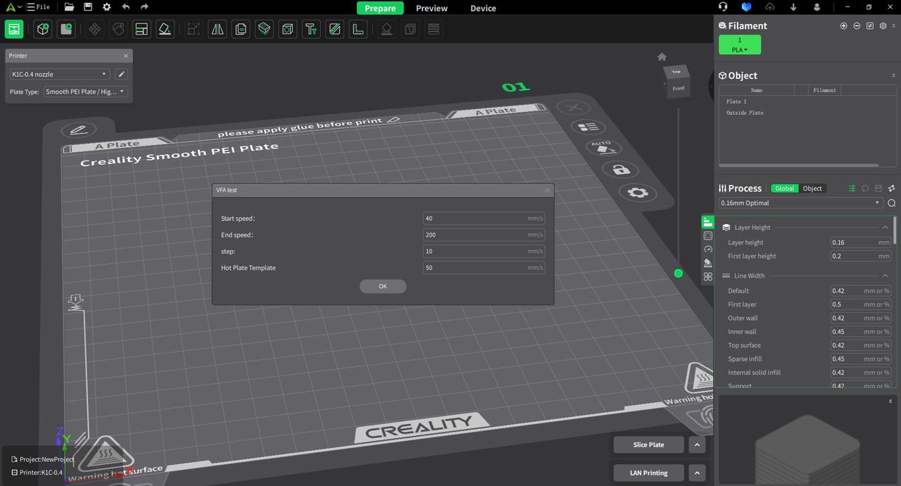
In the "Calibration" tab, select "VFA." Enter three parameters: start speed, end speed, and step. The slicing software will generate a printing test model. By default, the start speed is 40, the end speed is 200, and the step is 10.
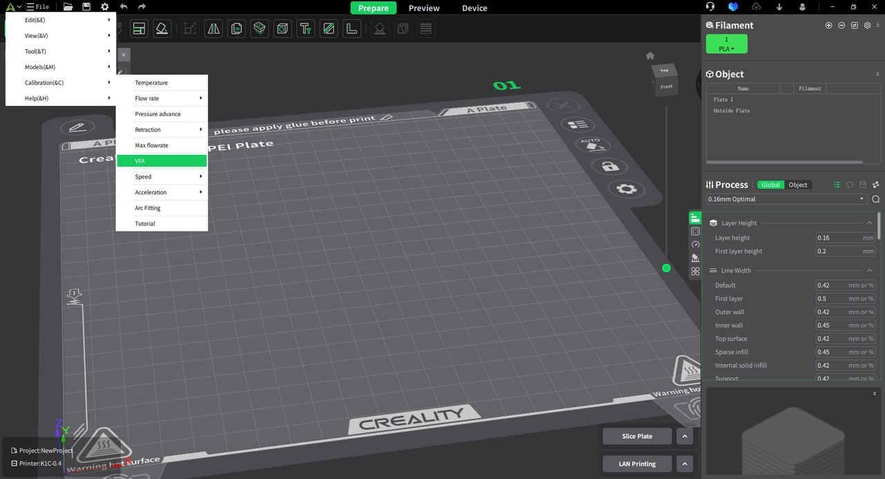
¶ Entrance for VFA
¶ VFA settings
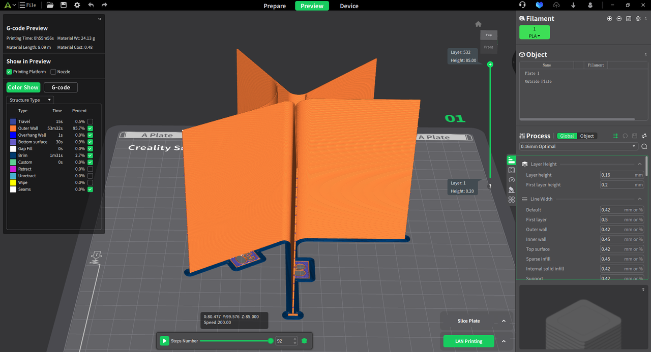
¶ View preview effect
¶ Analyze the printing results and adjust relevant parameters
1. Result analysis
During the comparison of actual printing results, we found that when the speed exceeded the fifth increment, the low-speed vibrations caused by the printer hardware disappeared, and there were no vibrations or abnormal layer lines as the speed increased further.
Conclusion: The speed at the fifth increment is approximately 100mm/s, so it is recommended to set the outer wall speed to at least 100mm/s or higher.
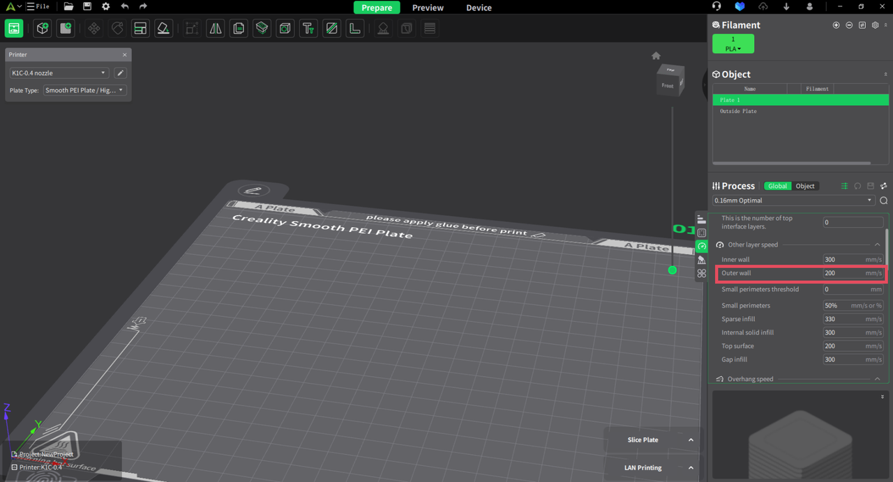
2. Parameter adjustment
Modify the outer wall speed value to be 100mm/s or higher in the process management.
¶ Credits:
- **The Flowrate test and retraction test is inspired by SuperSlicer*.
- *The PA Tower method is inspired by Klipper.
- *The temp tower model is remixed from Smart compact temperature calibration tower.
- *The max flowrate test was inspired by Stefan(CNC Kitchen), and the model used in the test is a remix of his Extrusion Test Structure.