¶ Layer height
¶ 1. Layer height
Layer height refers to the height of each layer of the printed product. The higher the value, the faster the printing speed and the lower the resolution;The lower the value, the slower the printing speed and the higher the resolution.
Explain in more professional detail: The height of each layer in the plastic layer-by-layer stacking process represented by the 3D printer represents the layer height. Layer height is the thickness of these layers in millimeters. It is the most important factor affecting the final print's visual quality and print time.
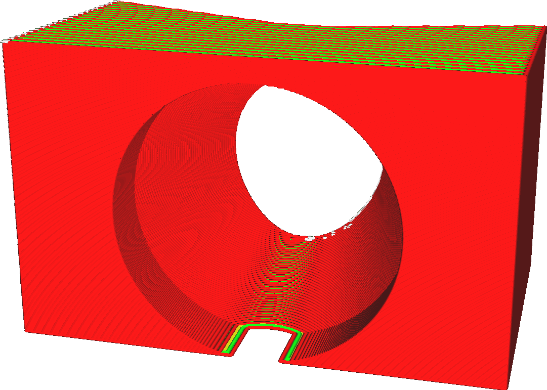
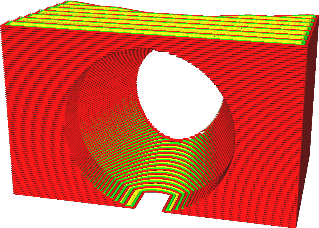
So we know that layer height is the most important setting that affects overall quality and print time. The following is a summary of some of the impacts of changes in layer height (thinner, thicker):
• Thinner layer heights improve the visual quality of your prints. As the layer height is thinner, the step effect between layers is reduced. In addition, the wrinkles between layers will become smaller, and the overall surface will appear smoother.
• Thinner layer heights allow the printer to produce more detail at the top and bottom of your prints.
• Thicker layer height will make the print target somewhat stronger. There will be fewer boundaries between layers, and these boundaries are often weak spots. Thicker layers will not produce excessive shearing.
• Thicker layer heights reduce print times because the nozzle does not need to move as much horizontally.
¶ 1.1 Layer height vs. configuration file
Many settings depend on layer height. Because layer height significantly affects the flow rate of material through the nozzle, many parameters of the printing process will change. This has a certain level of complexity. For example, when increasing layer height, you may need to increase the print temperature slightly to offset the additional heat loss.
Temperature affects the fluidity of the material, thereby affecting Corner sharpness and required coolingetc. Therefore, it's best to start with a preset quality profile provided by your printer that has a layer height close to your desired layer height.
You can select the desired layer height in custom mode, but you can also use the preset profiles with different layer heights .
¶ 1.2. Additional instructions
At very low layer heights, you may encounter Z-axis resolution limitations. Find the step size of your printer's Z axis and make sure the layer height is a multiple of that. If they don't match, some layers will be thicker than others, resulting in a striped effect.
¶ 1.3. Scope of influence of Layer height
• Top/Bottom Thickness
• Number of top layers
•Number of bottom layers
•Minimum skin extension width
• Filling layer thickness
• Regular fan speed
• Supports overhang angles
• Support Z distance
• Distance on support
• Support fill layer thickness
• Support interface thickness
¶ Starting layer height
¶ 1.4 Initial Layer height
This setting defines the thickness of the first layer of the print.
The starting layer is usually printed thicker than the remaining layers to create stronger adhesion to the build plate, so The thicker the initial layer height, the stronger the adhesion to the printing platform. This setting allows you to increase the thickness of the starting layer without reducing the resolution of the rest of the print.

Increasing the thickness of the starting layer causes the nozzle to extrude more material over the same distance. This requires extra force because the material spreads to the sides to fill the entire line width. This extra force allows the material to adhere better to the build plate.
Also, thicker layers will capture any irregularities in surface flatness. If the build plate flexes slightly, the thickness of the first layer will absorb the change, otherwise the nozzle might scrape it off in the second layer.
A starting layer that is too thick will cause the first layer to sag more, resulting in an 'elephant foot' condition. The Initial Layer Horizontal Expansion setting can prevent this from happening by giving it a small negative value.
¶ Arc Configure Enable
¶ 2. Arc Tolerance
Concept description: 3D models are mostly represented as triangular mesh, which means that the final slicing and printing path is Dense line segments.
When the printer speed is slow, the impact of these dense paths on the print quality is not very obvious. However, when the printing speed is increased, a large number of transient pulse signals will be generated at the turning points of the printing path, causing noise and vibration.
To alleviate this problem, arc paths are generated during slicing by fitting within an acceptable tolerance. Thereby smoothing the path and reducing vibration, this is the role of arc Tolerance.
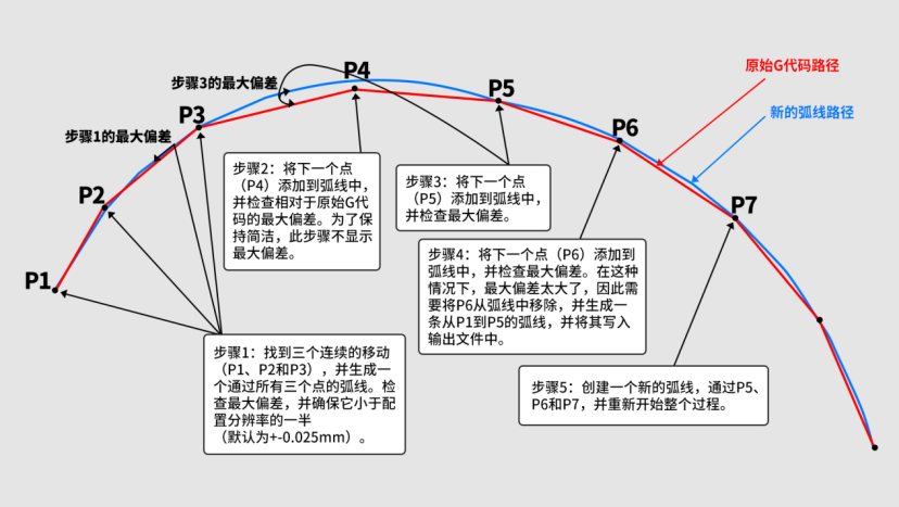
¶ 2.1 Fitting tolerance
Because the acrsin function and arccos function need to be calculated at each step, the calculation amount of arc is relatively large under high-speed conditions.
In some cases, the printing effect is not good, not because of mechanical limitations, but because the printer's processor cannot calculate line segments fast enough. As a result, some printers jam or reduce the printing speed, and the printing completion time is much longer than it should be. .
This function has certain requirements on the printer performance. The very small radius of arc printing is helpful for smooth and quiet printing. Printer processor performance and printing speed determine the length of arc line segments. Better hardware allows higher printing speeds, greatly reducing the cost of gcode files. size.
arc printing was not popular in the past few years. With the improvement of printer processor performance, more and more firmwares now support such as Marlin, Smoothieware, prusa, RepRap...
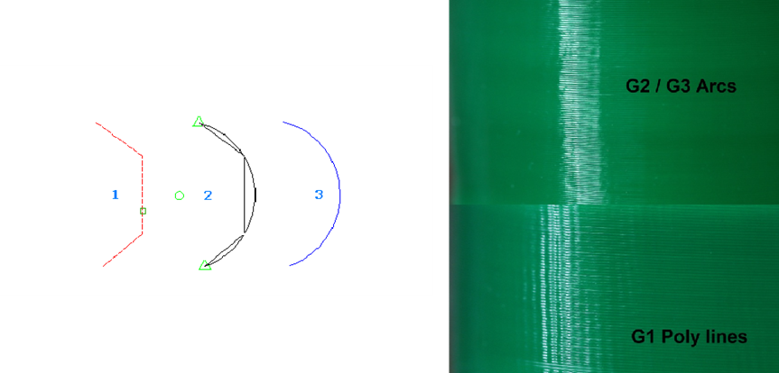
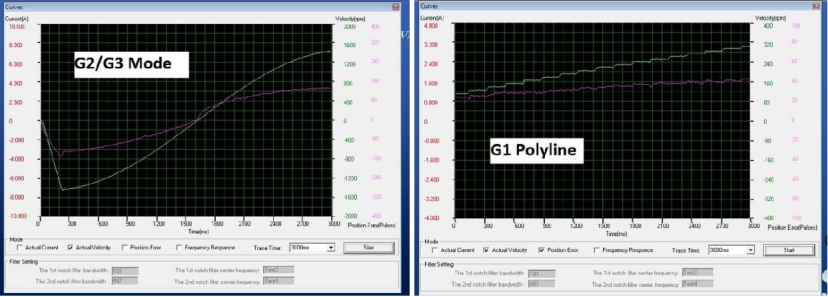
Through the comparison of high-speed printing, it is not difficult to see that G2/G3 can greatly reduce the minor defects caused by the printer's micro pauses .
¶ 2.2 arc server real-time response chart
As shown in the figure below, the real-time response chart of the large arc server. The green line is the axis speed, and the pink line is the pulse position error, showing a very large step characteristic. The size of the triangle side of the model determines the length of the line segment of G0, gcode The linear motion of the G2/G3 firmware and the axis are very much meshed with each other, and the motion of the two axes is more coordinated, producing a continuously smooth curve.
¶ Small Feature Max Length
¶ 3. Small Feature Max Length
Small details in prints are often critical to size. Feature outlines shorter than this length will be printed using the smaller feature speed set in advance. This setting causes the print's small feature outlines to be printed more slowly for higher accuracy.
If the small feature outline perimeter in the printed product is smaller than this setting value, the speed at which the perimeter of the small feature outline is printed Will be multiplied by a factor of small feature speed (usually reduced). This setting is a different way of approaching the Small Feature Maximum Size (#smallHoleMaxSize) setting.
A common use case for this feature is to print small feature outlines at very precise dimensions. When printing small feature outlines, the remaining material is often pulled into the corners together with the nozzle. If the corners are very sharp (such as the characteristic outline of a small hole), it will have the effect of making the hole smaller. However, when printing speed is slower, this pulling force will decrease, because the material has more time to stabilize, and the mechanical pulling force during printing It is also lower and does not produce excess material.
Increasing this setting will cause more contours to be marked as "small features". Printing speed will also be slower for areas of larger outlines in the print. This allows for more accurate printing of the outlines of these small features, but increases print time.
¶ Small Feature Speed
¶ 1. Small Feature Speed
Contours shorter than small feature maximum length can be printed at a slower speed. This setting allows you to specify the speed at which these small feature outlines are printed, as a factor in their Normal Print Speed.
When printing small feature outlines, if the corners are very sharp (such as the outline of small holes), makes the holes smaller</span style="font-weight: bold; color: purple"> span> effect. This pull is reduced when printing at slower speeds because the material has more time to settle and the mechanical pull is lower.
Reducing the speed at which you print the outlines of these small features will result in more accurate dimensions. However, it also increases printing time slightly. Fortunately, since these contours are by definition inherently small, the increase in total print time is usually not very great even if reduces the print speed .
¶ Normal printing speed
¶ 1. Normal printing speed
The speed at which walls are printed can be configured separately from the normal printing speed.
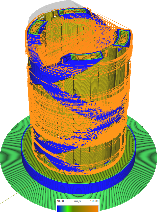
Wall is the most important factor affecting the visual quality of printed products. It includes outer wall and inner wall. The printing speed of the wall, especially the printing speed of the outer wall, is the main factor affecting the appearance of the wall. Therefore, it is recommended to print the wall at a fairly slow speed. This reduces vibration in the printer, ultimately reducing vibration amplitude in printing.
It also improves the quality of the draping, as slower print speeds allow the fan to better cool the wall, allowing it to hang more powerfully in the air.
However, if the wall print speed is too low, there is a risk of introduce too large a flow change. If the nozzle suddenly has to extrude at a slower speed, it will still extrude a lot of material over a period of time while the pressure in the nozzle chamber drops, so at the beginning of the wall it will overextrude.
So we can conclude that the wall is also an important part of the printing time. If reduce the speed of printing the wall it will greatly increase the printing time. time.
¶ Maximum size of small features
¶ 1. Maximum size of small features
The size of the print is often critical to the print effect of small details. This setting causes small feature outlines in the print to be printed more slowly for higher accuracy.
If the diameter of the small feature outline in the print is smaller than this setting value, the speed of printing the perimeter of the small feature will be multiplied by Small Feature Speed by a factor (usually reduced). See Small FeatureMaxLength; this is the actual setting used for slicing.
A common use case for this feature is printing small feature outlines at very precise dimensions. When printing small feature outlines, residual material tends to be pulled into the corners with the nozzle. If the corners are very sharp (such as the characteristic outline of a small hole), it will have the effect of making the hole smaller. However, when printing speed is slower, this pulling force will decrease, because the material has more time to stabilize, and the mechanical pulling force during printing It is also lower and does not produce excess material.
Add thisSettings will cause more contours to be marked as "small features". Printing speed will also be slower for areas of larger outlines in the print. This allows for more accurate printing of the outlines of these small features, but increases print time.
¶ Enable bridge settings
¶ 1. Enable bridge settings
When your model has some overhangs that are supported on both sides, Creality Print will detect this, and modify Overhanging skin areas for better printing. If you enable this setting, you can adjust the detection of these bridge areas and the resulting behavior for better bridging, further improving print quality .
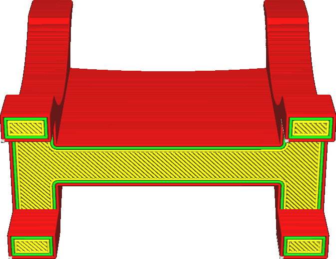
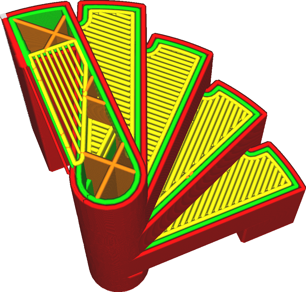
Normally Creality Print will use fairly basic bridging technology. Creality Print will detect skin overhang areas that are supported on multiple sides. Adjust Skin Line Directions to automatically bridge these areas. This ensures that the largest possible portion of the overhang area is supported on multiple sides and improves print quality.
Enabling this setting allows you to tailor the behavior more precisely to your requirements. This allows you to adjust:
• Printing speed
• Traffic
• Density (similar to fill density, but with skin lines)
• Fan speed
• For wall use, also for sliding
These settings can be adjusted individually for skin that bridges gaps and for walls. If you enable [Bridge Has Multiple Layers] (#bridgeHasMultipleLayers), you can also adjust the second and third layers above the bridge gap individually. It also allows you to adjust which parts of the print are considered bridged areas by adjusting which parts of the area must be in the air and the minimum width of the walls.
By enabling bridging settings, you can have more control over how bridging is handled in printing. By finely tuning the bridging parameters you can significantly improve suspension Stretch quality and improve vertical accuracy. If this setting is not enabled, printing results will usually be worse.
¶ The bridge has multiple layers
¶ 1. The bridge has multiple layers
If this setting is enabled, skins on higher layers above the bridge will also be adjusted. You can then carefully adjust the flow, velocity, density, and fan speed of the second and third tiers above the bridge.
The first level across the bridge is by far the most influential on the bridge’s appearance. If there is any sagging in that layer, there will be nothing to support it. For the second and third layers, there will be material underneath them that can bear (part of) the weight of the top layer. However, adjusting the top layer can still have some positive effects.
• Reducing density reduces the weight of the underlying material.
• Increasing fan speed can reduce material sag, thereby reducing the weight of the underlying layer.
• Lowering the print speed has a similar effect to increasing the fan speed in that it allows the fan to blow more Material.
• Reducing flow can reduce material weight and improve cooling.
However, there are other effects that make each of these settings a balancing act. Enabling Layer 2 and Layer 3 bridging settings also allows for more precise tuning, but also requires more experimentation to get good results.
¶ Start layer expands horizontally
¶ 1. Start layer expands horizontally
This setting only extends the initial layer located on the build plate (printing platform). Similar to Horizontal Expand, positive values will make the initial layer wider and negative values will make the initial layer smaller.
The initial layer is usually printed on a heated printing platform, keeping it slightly liquid to improve adhesion to the printing platform. The initial layer is also usually much thicker than the remaining layers. This allows enough time and material for the layers to sag sideways, creating a phenomenon known as the "elephant foot" that the print The underside has a slightly wider edge. This setting can compensate for the "elephant foot" by making the initial layer thinner in advance.
Set this setting to a small negative value to compensate for the occurrence of "elephant feet".
¶ Horizontal expansion
¶ 1. Horizontal expansion
This setting makes the entire model slightly wider or narrower. It is a compensation measure for size errors during the printing process.


¶ Horizontal expansion
¶ 1. Horizontal expansion
This angle represents Creality Print. Any corners sharper than this angle will be filled with variable width lines.
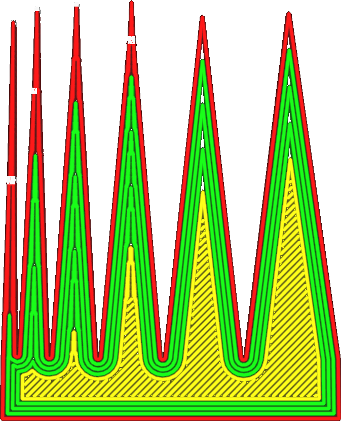
This effectively turns variable line width on or off for certain corners. If two opposing walls are nearly parallel and smaller than the angle specified in this setting, the area between them will be filled with lines that may vary in width. If they are at a larger angle to each other, the space between them will be filled with equal-width walls.
As always, it’s a trade-off. There are some advantages to using variable width, such as:
• Leave no gaps between lines.
• It will not fill the same space more than once.
• Print sizes will be more accurate.
But it also has some disadvantages:
• It introduces corners in the sheet that may appear as ripples on the surface.
• It generates an additional travel action.
• The printer may not be able to change line widths accurately in quick succession. In practice, it is best to make this angle large enough to reduce the size of the sharp corner gap, as can be seen in the layer view That, but otherwise as small as possible. Smaller angles generally make surfaces look smoother. It is not possible to reduce the angle to 0° to completely eliminate variable line width. Parallel and opposite walls will always adjust their line width to fit the space. This setting applies not only to regular walls, but also to additional skin walls, support walls, infill walls, and concentric patterns.