¶ 1. Infill density
¶ 1.1 Infill density
This setting configures the density of the print's internal volume, which is a major factor in the final print strength, as well as the quality of the top surface.
The greater the fill density, the closer together the fill lines are placed. You can even set the fill density above 100%, but this will result in over-extrusion.
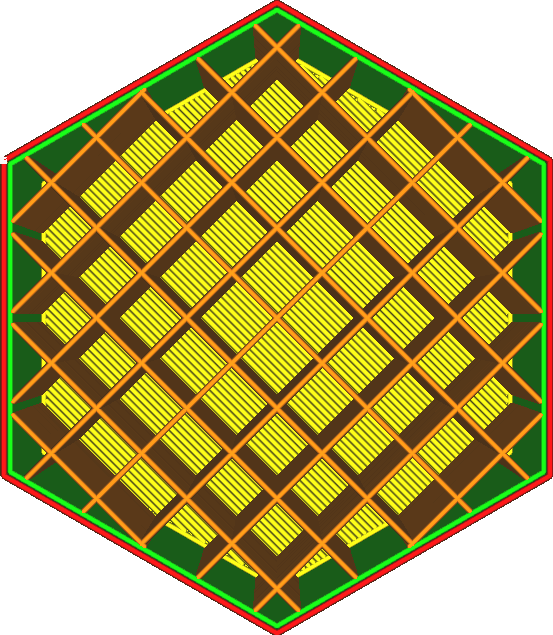
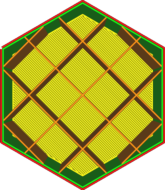
The printing effect will be better if different densities are combined with different fill patterns.
However, hatch patterns with a lot of corners and intersections don't work well with high fill densities. Corners are a problem because the filament tends to drag with the corners, creating air pockets on the outside of the corners where material should be deposited.
Crossing is a bigger problem because when one line crosses another, its flow is interrupted, resulting in insufficient extrusion after crossing.
Increasing the filling density (by reducing the line distance) has a great impact on the printing effect, namely:
• The printing effect will be stronger.
• The top surface will be better supported, making it smoother and more waterproof.
• Reduce pillowing as the heat zone will be smaller.
• Your print will require more material and will therefore be heavier.
• Printing takes a long time.
¶ 2. Infill Line distance
¶ 2.1 Infill Line distance
The distance between the fill traces during printing. This setting is calculated by the density of the fill and the width of the fill line.
In addition to setting the fill density as a percentage, you can also configure the fill density by setting the distance between adjacent fill lines. The greater the distance between fill lines, the lower the overall fill density. Fill line distance is a different way of looking at this property than density.
The distance between hatch lines indicates how far the top line must cross from one hatch line to the next. Reducing fill line distance reduces bridging distance and improves top surface quality.


¶ 3. Infill pattern
¶ 3.1 Infill pattern
refers to the pattern of printed fill material. Lines and zigzag fills swap directions on alternating layers, reducing material costs. Grids, triangles, inner triangles, cubes, octagons, tetrahedrons, crosses and concentric patterns are printed in full on each layer. Spiral tetrahedra, cubes, tetrahedrons, and octagonal infills vary with each layer to provide a more even intensity distribution in all directions.
A hatch pattern defines the structure used to fill the volume of an object. There are several modes to choose from, each with its own advantages. Some are designed for very specific applications.
¶ 3.11 Grid

A grid fill pattern creates two sets of vertical lines. Together this forms a square pattern.
• The strongest pattern in the vertical direction.
• The lines are quite strong in both directions.
• Diagonals are not too strong.
• Very good at supporting the top surface and the top surface will look very smooth.
¶ 3.12 Straight line
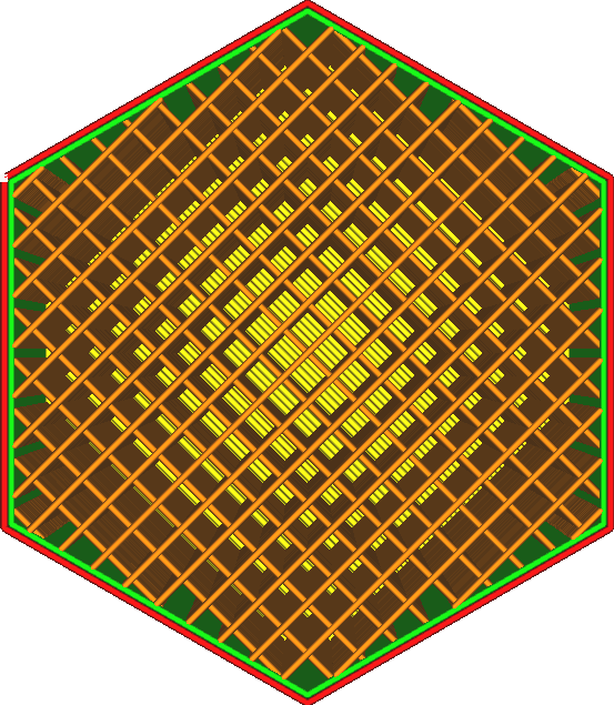
A straight line pattern creates multiple parallel lines. By default, a pattern of straight lines alternates its direction vertically from layer to layer, making it look like a grid pattern at first glance.
This pattern setting has the following characteristics:
• Tends to be weaker in the vertical direction because the layers only have small dots that are glued together.
• The intensity in the horizontal direction is very weak except in one direction in which the lines are oriented. But even in this orientation, it does not resist shear forces, so it fails quickly under load.
¶ 3.13 Triangle
The triangle pattern creates three sets of lines in three different directions. This creates a triangular pattern.
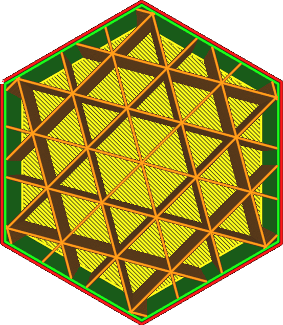
The characteristics of the triangle pattern are as follows:
• Very resistant to shear.
• The intensity in each horizontal direction is approximately equal.
• Top lines must bridge considerable distances, requiring many top skin layers to obtain a uniform top surface.
• The flow is significantly interrupted at the intersection, resulting in relatively low strength at high filling rates.
¶ 3.14 Hexagon socket
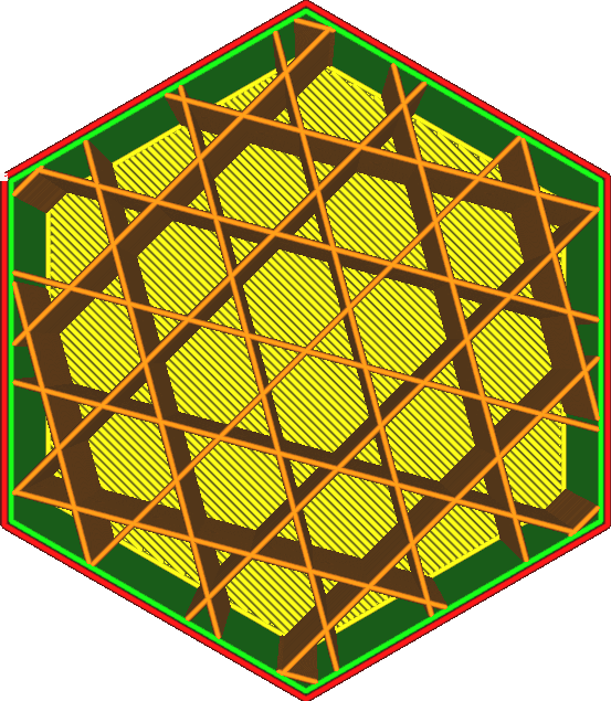
The hexagon pattern is all about creating three sets of lines in three different directions, somewhat similar to the triangle pattern, but offset from each other so that they don't all intersect at the same location.
It has the following characteristics:
• The strongest pattern in the horizontal direction.
• The intensity in each horizontal direction is approximately equal.
• Very resistant to shear.
• The top lines must be bridged over long distances, requiring many top skin layers to obtain an even top surface.
¶ 3.15 Cube
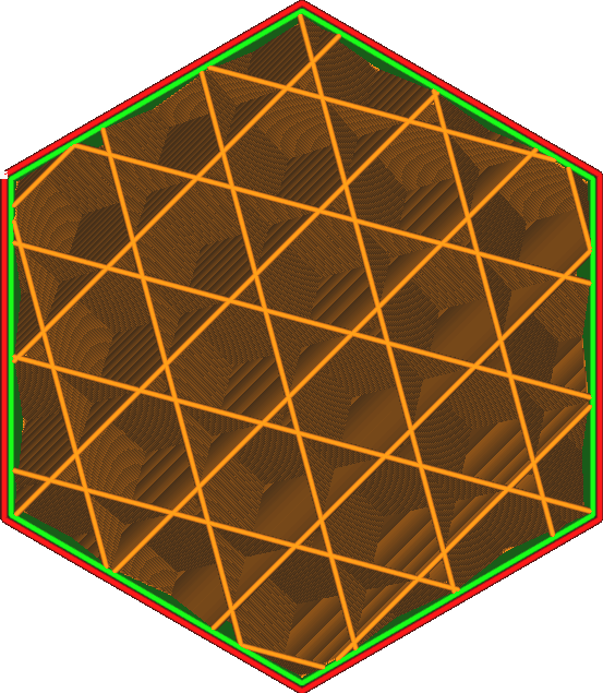
Cube pattern creates a cube, which is a 3-dimensional pattern.
The cubes are oriented to stand on the corners, which allows them to be printed without overhanging the interior surfaces.
It has the following characteristics:
• Intensity is approximately equal in every direction, including vertically.
• Quite powerful in every aspect.
• Reduces the pillow effect as it does not create long vertical masses of hot air.
¶ 3.16 Cube Partition
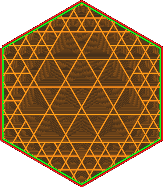
The Cube Partition Pattern mode creates a cube, which is a 3-dimensional pattern. The cubes are oriented to stand on the corners, which allows them to be printed without overhanging the interior surfaces. However, this mode creates a larger cube inside the volume, thus saving material. It omits fill lines in the most useless places.
This pattern may produce a lower than desired fill density. It is recommended to significantly increase the fill density when using this mode. This optimization works best at high fill rates.
Algorithmically, the pattern is generated by creating a giant cube around the entire volume, then subdividing the cube into 8 sub-cubes when it hits any wall. Then recurse, so subcubes hitting any wall are subdivided again and again. Repeat this until the fill line distance is reached.
It has the following characteristics:
• Strongest pattern by weight and print time.
• Intensity is approximately equal in every direction, including vertically.
• Concentrate filling into flakes.
• Reduces the pillow effect as it does not create long vertical masses of hot air.
• If you use increased infill density, the infill does not show through the wall as much, resulting in a better surface quality in the same print time.
• Introduce retraction functionality, which does not work well with flexible or flowing materials.
• Slicing takes longer.
¶ 3.17 Octagon
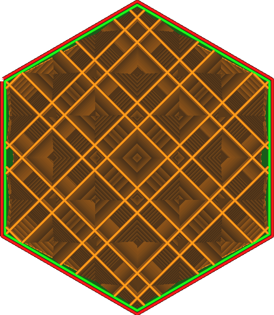
The octagonal pattern creates a combination of regular tetrahedrons and cubes, a 3-dimensional pattern. Every once in a while, multiple fill lines are placed next to each other.
It has the following characteristics:
• Create a strong internal frame where multiple parallel lines intersect. The load is quickly dissipated onto this internal frame.
• Strong strength for medium models with a thickness of approximately one centimeter.
• Reduces the pillow effect as it does not create long vertical masses of hot air.
• Result in very long bridging distances of the top skin, thus reducing top surface quality.
¶ 3.18 Tetrahedron
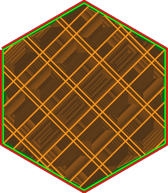
Tetrahedral patterns are created from a 3-dimensional tessellation of tetrahedrons and truncated tetrahedrons.
Every once in a while, multiple fill lines will be placed next to each other.
• Creates two discontinuous inner frames, similar to octets, where multiple parallel lines touch. The load is quickly dissipated onto this internal frame. The frames are oriented in two different directions, making them each weaker but reducing the distance over which the load is distributed to these frames.
• Strong effect on models only a few millimeters thick.
• Reduces the pillow effect as it does not create long vertical masses of hot air.
• Result in very long bridging distances of the top skin, thus reducing top surface quality.
¶ 3.19 Concentric circles
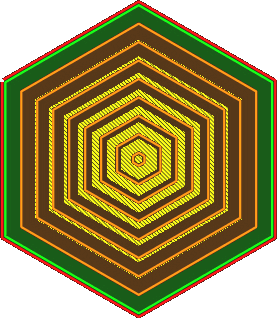
A concentric circle pattern forms rings parallel to the wall.
• When using 100% infill, the strongest infill pattern is used, because not only will no lines intersect, but the direction of the lines also makes the strength of the lines in all directions evenly distributed, sharing the load.
• Ability to print very flexible models with very uniform strength in all horizontal directions.
• Vertical direction is stronger than horizontal direction.
• At 100% infill density, material may clump in the middle, reducing printing reliability for circular shapes where concentric circles converge at one point.
• For some shapes, some fill lines may hang in mid-air, adding no extra strength to material cost and print time.
• When not using 100% fill, this is the weakest fill pattern in the horizontal direction. The internal gaps are too large and there is no filling and interweaving so there is no force gathering, so it does not add any power at all.
¶ 3.20 Jagged
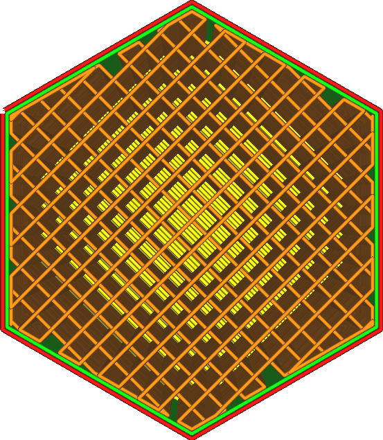
The zigzag fill pattern causes the nozzle to draw lines in a zigzag pattern.
It's like a line, but the lines are connected into one long line, which prevents traffic interruptions.
• The second strongest fill pattern when using 100% fill. However, it prints more reliably than circular concentric fills.
• Smooth tops and zigzags are the best patterns because the distance between lines is minimal.
• Tends to be quite weak in the vertical direction because the layers only have small dots that are glued together.
• The intensity in the horizontal direction is very weak except in one direction in which the lines are oriented. But even in this orientation, it does not resist shear forces, so it fails quickly under load.
¶ 3.21 Crossover
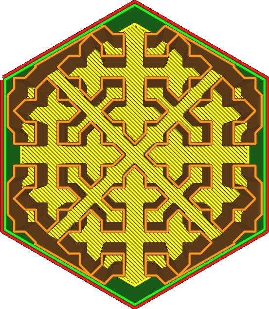
The cross-fill pattern produces a space-filling curve, resulting in something that looks like a cross along the interior of the volume.
Its features:
• Flattens evenly in all horizontal directions, which is useful for printing soft and stretchy objects.
• Does not create long straight lines in the horizontal direction, making it soft evenly along the entire perimeter. Nothing strong.
• No retraction at all, making it easier to print with flexible materials.
• Vertical direction is stronger than horizontal direction.
• Slicing takes a long time.
• Very weak in all horizontal directions.
¶ 3.22 Crossover 3D

The Cross 3D hatch pattern produces a space-filling curve that looks like a cross along the inside of the volume. The pattern is pulsed along the Z-axis to make it weaker in the vertical direction.
Its features:
• Extrudes roughly evenly in all directions (horizontally and vertically), making it the most useful pattern for printing soft and flexible objects.
• No long straight lines are created, resulting in even softness over the entire surface.
• No retraction at all, making it easier to print with flexible materials.
• Slicing takes a long time.
• Very weak in all directions.
¶ 3.23 Spiral icotahedron
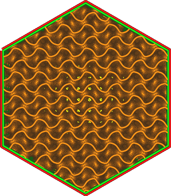
The spiral fill pattern produces a wavy pattern in alternating directions.
• Generates a fully liquid-permeable volume, making it a useful model for dissolving materials.
• Equally strong in all directions, but not very stiff. This makes it useful for flexible materials, but the result will be stiffer and less flexible than a cross (3D) fill pattern.
• There are no overlapping lines in this pattern, which makes it easier to print with materials with higher surface tension and makes infill very reliable and consistent.
• Resistant to shearing.
• Slicing takes a long time and generates large G-code files. It can be difficult for some printers to keep up with the many G-code commands per second, and it can be difficult to keep up with serial connections at low baud rates.
¶ 3.24 Lightning Shape
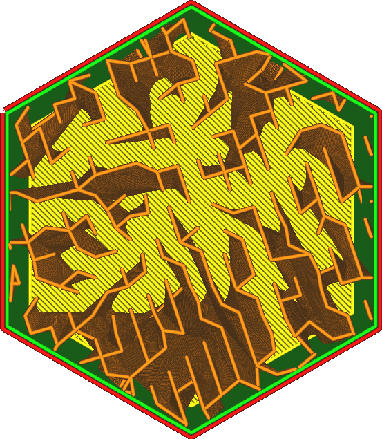
The lightning pattern gradually forms from the side
The lightning fill pattern is a zigzag minimal pattern that is used only to support the top surface.
The specified packing density can only be achieved directly below the top side of the packing volume.
• Infill is generated only beneath the surface, saving significant time and material.
• Increasing infill density allows for the best top surface quality for all patterns without spending more time and materials.
• You can prevent filler in many places from shining through the wall simply by not using filler.
• Does not increase the strength of the part in any significant way.
¶ 4. Infill Line multiplier
¶ 4.1 Infill Line multiplier
This setting converts each fill trace into a multi-trace. The extra traces do not cross each other, but avoid each other. This makes infilling tighter but increases print time and material usage.
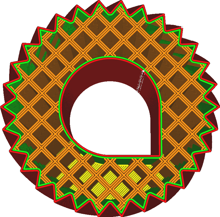
This increases the strength of the fill compared to simply increasing the fill density, as the fill lines are able to tilt toward each other for additional stiffness. When setting an odd multiple, the original hatch lines will remain in place, but additional hatch lines will loop through the holes of the hatch pattern. When setting an even multiplier, the original fill line will be removed and the loop will be placed directly in its place.
This will have some impact on your print compared to the alternative of increasing the infill density by the same multiple:
• The fill becomes stiffer overall, similar to increasing fill line width, because the fill lines are able to tilt toward each other when subjected to shear forces.
• Fillers can shine through the skin more, reducing surface quality.
• The gaps between fill lines are larger because the fill lines are clustered together more. This will cause the skin to sag more and allow for pillowing. This setting has no effect if the fill density is 100% or higher.
¶ 5. Infill overlap percentage
¶ 5.1 Infill overlap percentage
Concept description: Refers to the overlap between the filler and the wall as a percentage of the filler trace width. A slight overlap will allow the individual walls to be securely connected to the filling.
Padding Overlap Percent If the padding slightly overlaps the wall, it will adhere to the wall better, making the part stronger. This setting controls how much the fill overlaps the wall, expressed as a percentage of the fill line width.
Some characteristics of this parameter:
• Adding overlap allows the filler to bond better to the wall, creating a stronger piece.
• However, it can also cause the filler to shine through the wall, creating a pattern on the surface of the print. This reduces visual surface quality.
¶ 6. Fill overlap
¶ 6.1 Fill overlap
Concept description: Refers to the amount of overlap between the filler and the wall.
Padding Overlap Percent If the padding slightly overlaps the wall, it will adhere to the wall better, making the part stronger. This setting controls how much the fill overlaps the wall, expressed as a percentage of the fill line width.
Some features:
• Increasing overlap allows the filler to bond better to the wall, creating a stronger piece.
• However, it also causes the infill to glow through the wall, creating a pattern on the print target surface. This reduces visual surface quality.
¶ 7. Merge fill layers
¶ 7.1 Merge fill layers
Concept description: Automatically merge several layers of sparse fill to print together, which can shorten the time. The interior and exterior walls still maintain the original layer height printing.
¶ 8. Infill layers Combination
¶ 8.1 Infill layers Combination
Concept description: The thickness of each layer of filling material. This value should always be a multiplier of the layer height, otherwise rounding should be performed.

Since the height of the infill layer is not important for visual quality, you can use a thicker infill layer to reduce print time. This setting causes the fill layers to be grouped together whenever there are multiple fill layers directly on top of each other. Then it won't print any infill on some layers, but in the top layer of the combined layer it will squeeze out more material to compensate.
In layer view, the fill lines appear to be wider. When actually printing, the fill lines drop further down instead of spreading out horizontally.
The thickness of the filling layer must be a multiple of the ordinary layer height. If not, it will be rounded to the nearest layer height.
• Be careful not to increase it too much. When switching to and from fill, the flow rate through the nozzle needs to accelerate and decelerate significantly. This has some lag, so too little is extruded at the beginning of the filling and too much at the end.
• In the middle layer it will still print the infill at a lower layer thickness and there will be no infill in the layers around it. This can cause small fill lines to print along sloping walls.
¶ 9. Gradual Infill Steps
¶ 9.1 Gradual Infill Steps
Concept description: The gradual filling step mainly reduces the amount of filler used by reducing the filling density of the lower layer. Reduce the packing density by half as many times as you get below the top surface. The area closer to the top surface has a higher density, reaching the highest filling density.
This saves printing time and material without too much loss of surface quality. The main purpose of infill when printing visual quality is to support the top surface. This function only focuses the padding for that purpose. This setting indicates the steps in which the fill density is reduced. With each step, the filling density is halved.
For example, starting with a fill percentage of 20% as shown below, through two progressive fill example steps, the lower fill density will be 10% and 5% respectively.


¶ 10. Narrow Area Concentric Infill
¶ 10.1 Narrow Area Concentric Infill
Concept description: In the download area of the printing target, concentric circles are used to fill it. In the case of high density, the strength of the printed product will be higher, which can relatively improve the quality of the printing target.