¶ 1. Line width
¶ 1.1 Line width
Concept description: This refers to the single trace width of the printer. Normally, the diameter of the nozzle opening determines the width of the line, but by extruding more or less material, the printer can slightly vary the width of the line. Lowering this value slightly can improve the printing effect to some extent.
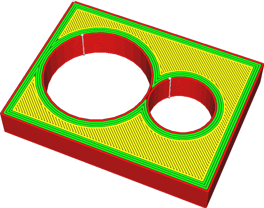
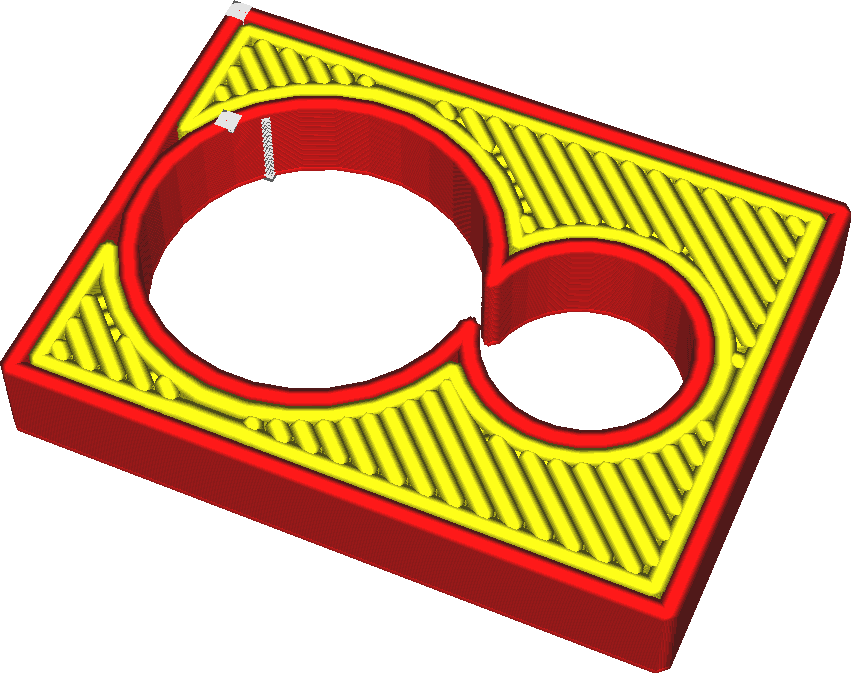
Reducing the line width allows the printer to print more details. In particular, it also allows the printer to print thin parts. Line width is one of the most influential settings in printing.
Here are some effects:
• Printing thinner lines will allow printing of thinner parts as it can fit lines into even the thinnest parts.
• Adjusting the line width to an even multiple of the print thickness can make the object sturdier and allow the material to flow better.
• Smaller line widths will make your top surface look smoother.
• Printing lines slightly smaller than the nozzle size tends to increase strength. It allows the nozzle to blend adjacent lines together as the nozzle makes its second pass slightly beyond the previous line.
• Printing lines that are too wide can cause under-extrusion. The printer will try to extrude more material, enough to fill the desired line width. The material will try to flow in any possible direction. However, at some point, the back pressure will become too great such that the material will no longer flow all the way to one side of the very wide line. This will leave gaps between the lines.
• Printing lines that are too small can also result in under-extrusion. If the material does not flow through the nozzle fast enough, the surface tension of the material will cause it to condense into small droplets, making the extrusion uneven and leaving gaps between the droplets.
• Printing thinner lines will significantly increase print time.
¶ 1.1.1 Outer wall Lrace width
Concept description: Refers to the width of the outermost wall line. The line width of the outer wall can be adjusted separately from the inner wall. Lowering this value can print a higher level of detail.
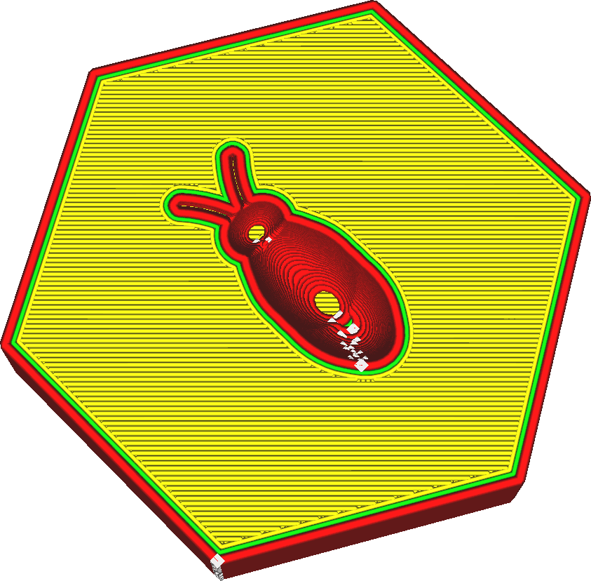
It is well known that reducing the line width of the outer wall to slightly smaller than the nozzle size is beneficial to increase strength. The nozzle will squeeze out slightly less material, but its opening will overlap the adjacent inner wall. This causes the material to be pushed into its correct position by the previously placed wall. But it will also allow the plastic to blend in better with adjacent walls.
This allows the exterior walls to blend better with the interior walls, thus combining their strength. This greatly increases the strength of the wall. Reducing the outer wall line width also allows the nozzle to print finer details, as thinner lines will better accommodate small details.
Increasing the line width of the outer wall can reduce printing time. You can achieve walls of similar thickness with fewer interior walls. There will still be some loss in strength because the outer wall won't blend well with the inner wall. In thin parts, the line width will automatically adjust to fit the local width of the part. There is no need to ensure that the width of the part is a multiple of the line width. The wall transition threshold angle determines where line widths are automatically adjusted at sharp corners. The minimum wall line width determines how far they can be adjusted in each direction.
¶ 1.1.2 Inner wall(s) Line Width
Concept description: Refers to a single wall line width that applies to all wall lines (except the outermost wall). The line width of the inner wall can be adjusted separately from the outer wall. This setting sets the width of individual interior wall lines.
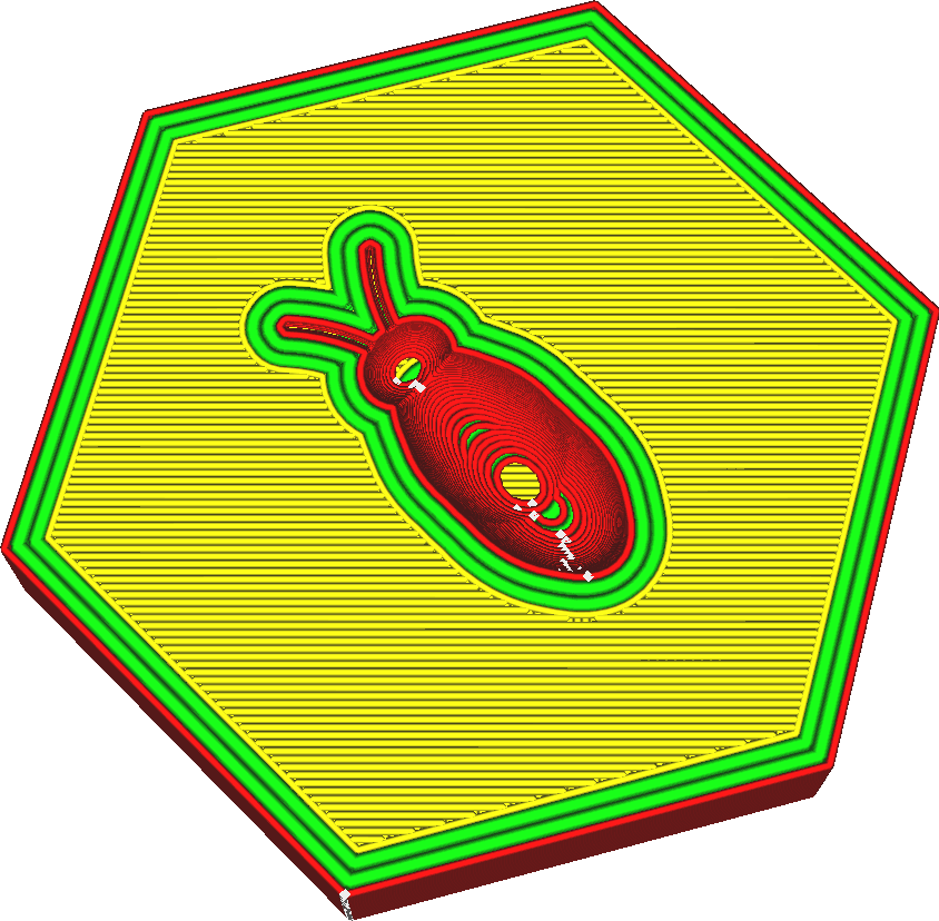
It is well known that reducing the line width of the inner wall to slightly lower than the nozzle size is beneficial to the improvement of strength. The nozzle will squeeze out slightly less material, but its opening will overlap the adjacent wall line. This causes the material to be pushed into its correct position by the previously placed wall. But it will also allow the plastic to blend in better with adjacent walls.
This allows the walls to blend together better, combining their strength. This greatly increases the strength of the wall. Increasing the inner wall line width can reduce printing time. You will need less inner wall to get a part with similar strength. There will still be some reduction in strength because adjacent walls won't blend together as much. In thin parts, the line width will automatically adjust to fit the local width of the part. There is no need to ensure that the width of the part is a multiple of the line width. The wall transition threshold angle determines where line widths are automatically adjusted at sharp corners. The minimum wall line width determines how far they can be adjusted in each direction.
¶ 1.1.3 top/bottom Line width
Conceptual description: Refers to the trace width of a single top/bottom layer. The width of each top and bottom line drawn. The width of the line can be different from the nozzle size by simply extruding more or less material than needed.
If more material is squeezed out, the plastic will flow to the sides, making the lines thicker. If less material is extruded, the surface tension of the material will tend to pull the material toward the centerline of the nozzle path.

Making skin lines wider is an easy way to reduce printing time because fewer lines are needed to print the top and bottom sides of the object.
However, increasing it too much can lead to huge squeeze-out fluctuations. This results in under-extrusion when printing the skin, and over-extrusion when printing anything that follows, because the flow through the nozzle isn't adjusted fast enough.
Increasing the width of the skin line will also increase the chance of holes appearing on the surface, which is not only unsightly but also detrimental to waterproofing. Reducing the width of the skin line will often produce a better top surface, but will take a lot of printing time. It's often more effective to use different techniques, such as ironing or just adjusting skin lines that are too superficial.
¶ 1.1.4 Infill Line Width
Concept description: Refers to the width of each filled trace drawn. The width of the line can be different from the nozzle size by simply extruding more or less material than needed.
If more material is squeezed out, the plastic will flow to the sides, making the lines thicker. If less material is extruded, the surface tension of the material will tend to pull the material toward the centerline of the nozzle path.
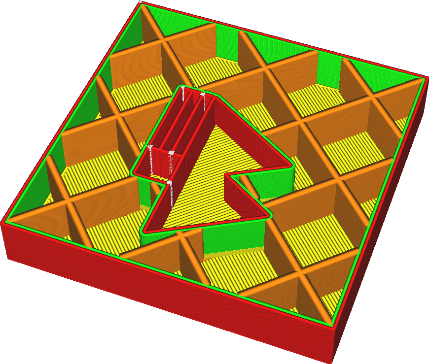
Making fill lines wider can make the print stronger and reduce print time.
However, adding too much can result in a very volatile squeeze. This results in under-extrusion when printing the infill, and over-extrusion when printing anything after the infill, because the flow through the nozzle isn't adjusted fast enough.
¶ 2. Initial layer Line width
¶ 2.1 Initial layer Line width
Concept description: Refers to the first layer trace width multiplier. Increasing this multiplier will improve the adhesion of the hot bed.
This makes the lines in the initial layer proportionally wider or thinner.
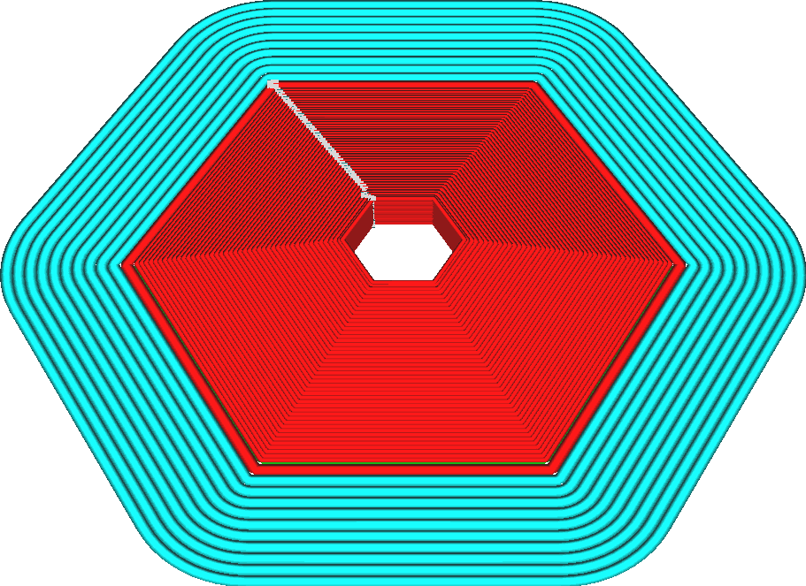
The purpose of this setting is to improve adhesion to the build plate. To print wider lines, the nozzle must squeeze out more material, and that material must flow outward wider. This causes the nozzle to press the material harder against the build platform, increasing the adhesion between the filament and the build platform.
• Not only will the lines become wider or thinner, but the distance between them will also be drawn farther or closer by the same factor, so there is no over- or under-squeezing.
• This setting affects all lineweights: skin, wall, adhesion, support, base tower, etc. They will become wider or thinner in the same proportion.
¶ 3. Enable Retrieval
¶ 3.1 Enable Retrieval
Concept description: Refers to retracting the filament when the nozzle moves above the non-printing area.
If the 3D printer stops pushing the material, the material does not immediately stop flowing from the end of the nozzle. There is some residual material in the nozzle and it is pressurized so it continues to flow for a while.
To stop the flow of material, the printer needs to retract the material from the nozzle opening. This is necessary for a clean traveling motion without stringing.
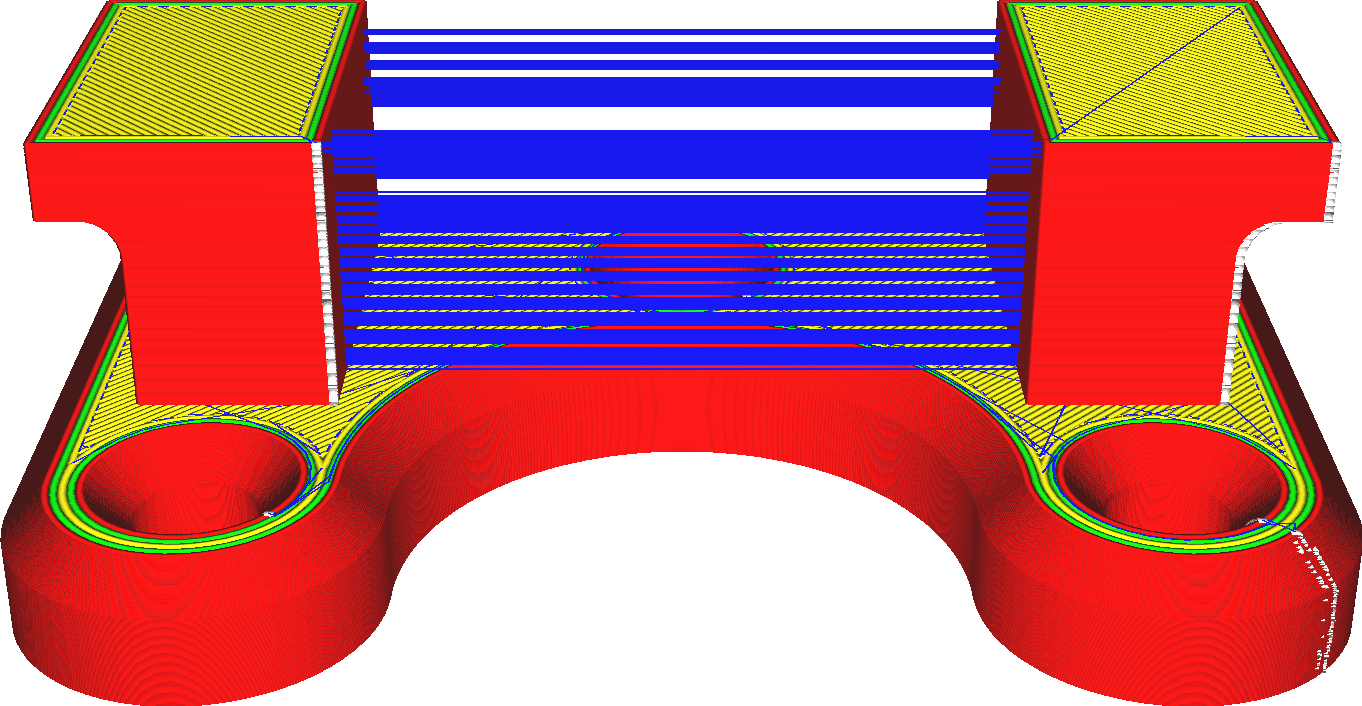
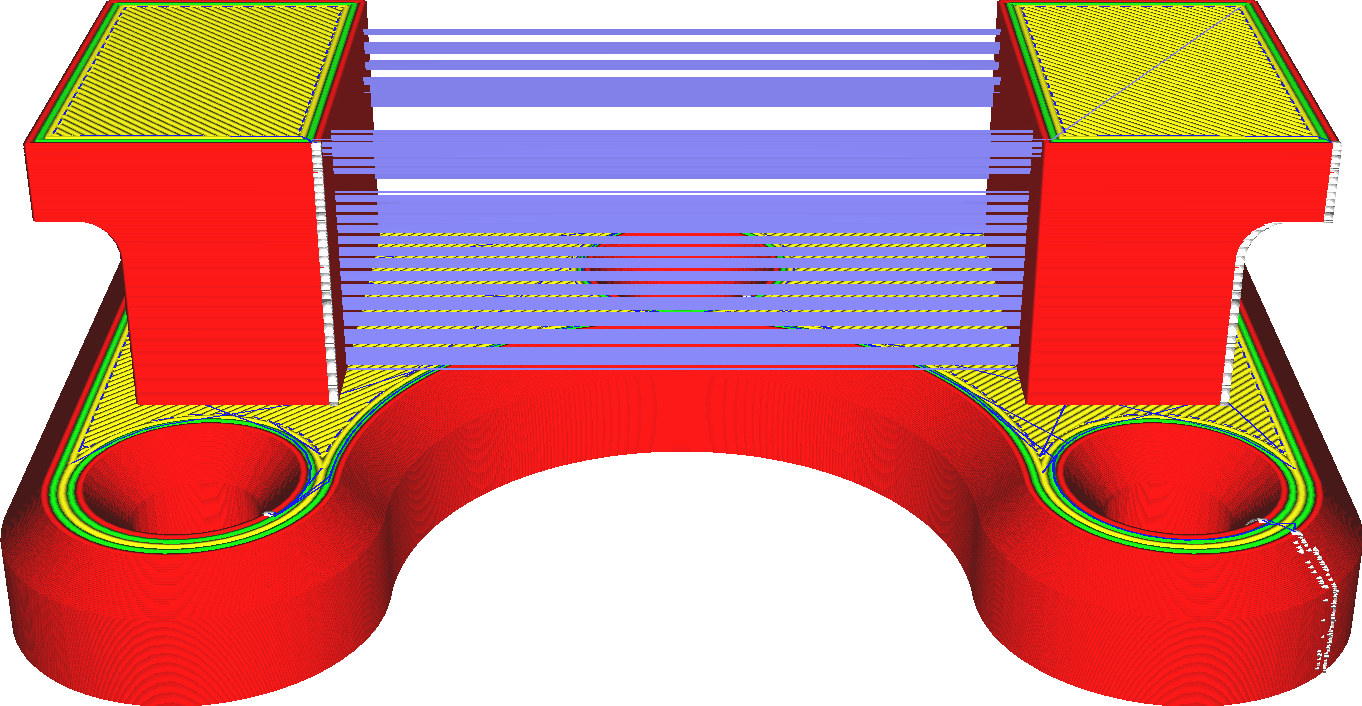
Retraction occurs when making traveling movements that are particularly sensitive to string pulling. Traveling only through fill or from support to support will generally not retract. The frequency of material retraction is also limited through the Maximum Retraction Count and Minimum Extrusion Distance window settings.
While material retraction has significant advantages, it also has some disadvantages:
• It will significantly reduce stringing. No more wiring is required between different parts of the print.
• It will significantly reduce the number and size of spots on the surface where the nozzle enters the perimeter of the part.
• Retrieval takes some time.
• When retraction occurs, the material flow is interrupted. This can negatively impact dimensional accuracy, banding and under-extrusion.
• When too much retraction occurs, the filament can become worn, preventing the feeder from clamping the material. Flexible materials are more difficult to retract because pulling on the filament stretches the filament rather than pulling it out of the nozzle. Enabling this material to retract can be time-consuming and relatively ineffective.
¶ 4. Retraction Wipe
¶ 4.1 Retraction Wipe
Concept description: This setting will wipe the nozzle when retracting the filament. If this setting is enabled, the material will retract throughout the wiping process. This can be configured separately from normal recall.
The wiping process moves the nozzle all the way to the side of the printer, back and forth there, and then back again. This is essentially a long trip. Because this travel movement is longer than the average travel movement throughout the print process, you may want to retract material during this process even if retraction is normally disabled. Retracting the material will reduce the amount of material that comes out during the wiping process.
Material that bleeds out during the wiping process is usually wiped away with a brush. However, this material is then lost. So after the wipe is complete, there's going to be some under-squeezing because the material has seeped out rather than being placed in the correct spot.
On the other hand, retraction may take some time and cause unnecessary wear of the filament. If insufficient extrusion is not an issue, disabling retraction may save some time and improve reliability. For example, this method works well if the infill is printed before the wall, as some lack of extrusion during the infill process isn't really an issue.
¶ 4.1.1 Wipe length
Concept description: refers to the length of the wiping nozzle when withdrawing. This setting configures how far the material retracts as the wiping process proceeds.
This can be configured separately from the normal retraction amount. The wiping process moves the nozzle all the way to the side of the printer, back and forth there, and back again.
This is essentially a long trip. Since this stroke movement is longer than the average stroke movement throughout the print process, you may need to increase the retraction distance during wiping beyond that used during normal printing.
Retracting the material further will take more time and wear the filament faster, but will reduce the amount of material lost due to leakage.
¶ 4.1.2 Before Wipe Retraction Amount Percent
Concept description: Refers to the amount of withdrawal before wiping the nozzle during the withdrawal process.
¶ 4.1.3 Retract at Layer Change
Concept description: When the nozzle moves to the next layer, the filament is withdrawn. Such a retraction setting is conducive to better printing results in overlapping parts of different layers of the printing target when printing different layers. Switching between different layers for printing will not cause any retraction defects.
¶ 4.1.4 Retraction Distance
Concept description: Refers to the amount of withdrawal before wiping the nozzle during the withdrawal process.
This setting configures how far the material is retracted as the wiping process proceeds. This can be configured separately from the normal retraction amount. The wiping process moves the nozzle all the way to the side of the printer, back and forth there, and back again.
This is essentially a long trip. Since this stroke movement is longer than the average stroke movement throughout the print process, you may need to increase the retraction distance during wiping beyond that used during normal printing.
Retracting the material further will take more time and wear the filament faster, but will reduce the amount of material lost due to leakage.
¶ 4.1.5 Retraction speed
Concept description: Refers to the speed at which consumables are retracted during the retraction process. This setting can also be understood as configuring the speed at which the material retracts and does not retract during the wiping process.
This can be configured separately from the normal retraction speed. Since any material that bleeds out of the nozzle during this wiping process will be wiped away anyway, the retraction speed of this process may be slightly slower compared to the rest of the print. This reduces filament wear.
¶ 4.1.6 Retraction Retract speed
Concept description: Refers to the reloading speed of consumables during the retraction movement.
This can be configured separately from the normal retraction main speed.
Starting more slowly may result in small spots where the nozzle lands after the wiping process.
However, after a longer retraction of the wiping process, it may be necessary to start more slowly to allow the material to flow properly.
¶ 4.1.7 Retraction Prime speed
Conceptual description: It refers to the fact that some materials may ooze out when the printer is running empty. You can adjust this setting to compensate for the material. If it is retracted during the wiping process, the material will no longer be there after the wiping process is completed. retract.
When this happens, you may want to push the material a little further than the original retraction distance to compensate for any material lost despite the retraction. This can be configured separately from the normal extra primes.
The wiping process moves the nozzle all the way to the side of the printer, back and forth there, and then back again. This is essentially a long trip. Because this travel movement is longer than the average travel movement throughout the print process, more material may be lost to leakage. To compensate for this, you may need to apply more primer after the wipe-down procedure than after normal driving movements.
If you apply too much extra material to the primer, you will get some oversqueezing. This appears as a blob where the nozzle landed after the wiping procedure.
¶ 4.1.8 Retraction Minimum Travel
Concept description: Refers to the minimum idle distance required when retraction occurs. This helps achieve less drawback in a smaller area. This setting prevents the material from retracting during very short stroke movements. During these movements, material has little time to seep out of the nozzle, so retraction can do more harm than good.

The purpose of recovering the material is to prevent drawing. Very short stroke movements will not produce stringing because the material has not had time to flow out of the nozzle. A very short stroke movement of about a line width can even cause the lines to completely overlap so there won't be any room to pull the line.
Retraction, on the other hand, causes the nozzle to stand still briefly while the material moves.
This allows some material to flow and create a spot there. For these reasons, it is best not to retract when driving short distances, even if these tracks are on visible parts of the model.
Increasing this setting too much will cause stringiness in detailed parts of the model or where parts are close together.
¶ 4.1.9 Maximum Retraction count
Concept description: The feed wheel needs to grab the filament to move correctly. Retracting material often causes the feed wheel to wear down the filament to the point where it cannot clamp the filament properly.
This setting limits the number of retractions within a certain length of filament to prevent this grinding.
This setting indicates how often the filament is allowed to retract during the filament length indicated by the Minimum Extrusion Distance window setting. Any further retraction during this window will not retract, but simply travel without retracting.
The filament length within which the number of retractions is limited is a sliding window. For example, with a window length of 3mm and a maximum number of retractions of 10, this means that as long as the 10th retraction is more than 3mm from the filament retraction, a new retraction is allowed.
Reducing the maximum number of retractions will reduce filament wear. This is useful for softer materials such as PVA. However, it also increases the drawstring since it no longer retracts to the position it obviously needs to.
¶ 4.2.0 Minimum extrusion distance Window
Concept description: Refers to the maximum retraction count range. This value should be roughly the same as the retraction distance, so that the number of times a retraction passes through the same piece of material can be effectively limited. The feed wheel needs to grip the filament in order to move correctly. Retracting material often causes the feed wheel to wear down the filament to the point where it cannot clamp the filament properly. This setting limits the number of retractions within a certain length of filament to prevent this grinding. Retraction is limited by a combination of the maximum retraction count and this setting. Within the filament length indicated by this Minimum Extrusion Distance window setting, material retraction is not allowed to exceed the value of the Maximum Retraction Count.
The filament length within which the number of retractions is limited is a sliding window. For example, with a window length of 3mm and a maximum number of retractions of 10, this means that as long as the 10th retraction is more than 3mm from the filament retraction, a new retraction is allowed. Increasing the length of the extrusion window effectively reduces the number of retractions.
This makes the print more reliable, but increases the amount of stringiness and spots on the surface. This is especially useful for softer materials that are more sensitive to grinding.
¶ 4. Combing mode
¶ 4.1 Combing mode
Concept description: Combing mode can keep the nozzle within the printed area when the printer is idle. This will slightly extend the free travel distance, but will reduce the need for retraction. If carding is turned off, the material is drawn back and the nozzle moves in a straight line to the next point. Also avoid combing the top/bottom skin areas or only comb within the padding.
Combing is the practice of avoiding passing through the walls of a print target when moving from one place to another. Passing through walls tends to leave scars on the surface where the hot nozzle exits or enters the print volume, so this is generally undesirable.
Combing alone will only cause the nozzle to avoid the walls as it passes through the inside of the grid. However, it also allows to avoid printing parts with a travel function, which makes the nozzle avoid objects outside the volume.


If there is a path through the object from the start position to the end position without hitting any walls, that path will be taken without retraction. If the start and end positions are in completely independent paths, the nozzle will first move to the closest position of the two parts, then optionally retract (if retraction is enabled) and travel to the target path, optionally cancel Retract, then move through the new part to its final destination.
In both parts, it will avoid hitting the walls while passing through the interior. When moving from one part to another, it will avoid parts only if the "Avoid printing parts while traveling" setting is enabled.
The purpose of combing is to avoid going through the walls of the object and reduce the number of scars on the surface. It also reduces visible stringing on the outside, as it will still bleed when making travel moves, but this bleed is placed on the interior of the model. However, grooming also increases the length of the stroke. Sometimes a big detour is needed.
The following are the options in the drop-down list for this setting:
• Off: Disable the combination. Travel actions will always go directly to the target location. If it happens not to hit any walls, it won't retract. All: As mentioned above, the nozzle will not hit any walls as it passes through the interior of the print.
• Avoid crossing outer surfaces: In addition to going around walls, the nozzle also avoids the highest and lowest layers of skin. These are the visible layers and if the nozzle passes over them you may see scars on the surface. If water cannot be avoided, it will be withdrawn.
• Except skin: If possible, the nozzle will avoid touching any skin. It causes unnecessary shrinkage and a longer path of travel because it avoids the skin layer, even if the scar is not visible on the outside.
• Within Fill: The strictest of all modes, allowing only combing of fill. This allows it to avoid hitting the inner and outer walls, as well as hitting the skin. If the nozzle hits the inner wall, it is sometimes still visible on the outside because the outer radius of the nozzle may be wider than the inner wall. This prevents this effect. However, it requires more pullbacks because the path is often unavailable.
¶ 4.1.1 Avoid printed parts when Traveling
Concept description: The nozzle will avoid the printed part when running empty. This option is only available when the carding function is enabled.
Avoid printing parts when moving By enabling this setting, the printhead will try to avoid hitting other objects as it moves around the build volume. Instead, it takes a short detour. If a detour can be made without hitting any other objects, retraction will not be triggered unless the path length exceeds the "Max grooming distance without retraction" setting.


In addition to avoiding other parts, the marching action will also stay near the wall for as short a time as possible. This means that when exiting or entering a part through a wall, it will exit or enter perpendicular to the wall. This setting tends to improve the surface quality of your prints because the nozzle doesn't penetrate the wall as often.
Walking through the wall can leave scars on the wall, so this should be avoided. However, this setup does increase the amount of bleed, as more travel movements will be made without retraction, and the travel movements will be longer. For materials that see more water, it is recommended to disable and avoid other parts. There may be a slight increase in print time due to the longer stroke movement, but this is usually more than offset by the resulting reduction in retractions.
¶ 4.1.2 Avoid supports when Traveling
Concept description: During idling, the nozzle avoids the printed support. This option is only available when grooming mode is enabled.
Typically, CrealityPrint doesn't bother to have the nozzle avoid the support structure as well as other parts. With this setting, CrealityPrint will avoid hitting the support structure while driving.
The support doesn’t need to be pretty, so it’s not a problem if a spot ends up getting support. In fact, this may prevent spots from appearing on the wall. Also, scarring on the support is not a problem for its functionality. However, if the material bleeds through a lot, and a spot of bleed is applied in the same spot on each layer of support, the spot can build up so large that it eventually causes the nozzle to knock over the support structure.
In this case, it may be helpful to avoid support while traveling. Some advantages and disadvantages of enabling this setting include:
• Greater reliability because there is a lower chance of overturning a support by repeatedly hitting the same spot.
• The stroke is slightly longer, so there is more leakage.
• The exudate does not get wiped off on the support but ends up on the wall of the component where the nozzle travels.
• There may not be any path to avoid the supports, in which case the printer will retract and travel in a straight line, which creates extra time and may leave additional scars on the wall .
¶ 4.1.3 Travel Avoid distance
Concept description: The distance between the nozzle and the printed part to avoid when driving empty.
This setting defines how much clearance the nozzle maintains from other objects that need to be avoided when avoiding collisions with other objects.
Remember, this defines the distance between other objects and the centerline of the travel movement. Marching has no thickness. It is recommended to specify a value for this setting that is at least large enough so that the nozzle tip does not hit other parts.
Increasing the value of this setting reduces the chance of the nozzle striking a previously printed object as it moves around it. However, increasing the value of this setting also slightly increases the length of the stroke movement because the nozzle must make more detours.
Perhaps more pressingly, this reduces the chance of finding a valid path that is not too close to any previously printed part. If no valid path is found, the nozzle will (maybe) retract and travel in a straight line, regardless of what other parts will be hit anyway. Therefore, increasing this setting too much can also harm surface quality.
¶ 5. Z Hop when Retracted
¶ 5.1 Z Hop when Retracted
Concept description: Whenever retraction is completed, the printing platform is lowered to create a gap between the nozzle and the printing target. It prevents the nozzle from hitting the printing target during empty travel. Reduces the chance of knocking the print target off the print platform. If this setting is enabled, the nozzle will be slightly raised above the print when it needs to move from one location to another. The idea is to move the nozzle over the print, rather than hitting the previously printed part with the nozzle.
Whenever retraction is complete, the nozzle is raised (or the build plate lowered) to create a gap between the nozzle and the print.
This has several advantages:
• It prevents the nozzle from hitting the print during travel. When the nozzle hits the print, it leaves a noticeable scar, so it should improve the visual quality of the print wall.
• If material seeps out of the nozzle during travel, the seepage will be deposited where the nozzle lands after travel movement, which is usually not visible in the fill. This reduces spots on the surface.
• Spots on the surface have the potential to knock over prints, so enabling this setting can improve reliability. However, moving the nozzle up and down all the time takes more time, so the print takes longer to complete. It can also wear out the printer's Z-axis faster, depending on the printer's design.
¶ 5.1.1 Z Hop only over printed parts
Concept description: Refers to performing Z-lift only when moving above the printed part that cannot be avoided by the horizontal operation of the "Avoid printed part when driving empty" option. This setting causes the printer to more frequently try to avoid other objects horizontally instead of crossing them vertically. If the Avoid Printed Parts setting is enabled, the nozzle will avoid other parts as it moves from one place to another. Typically, if Z-lift is applied, it is no longer necessary to avoid printing parts.
This setting switches the logic: If printing the part cannot be avoided, Z-lift is applied. Z-jump can cause wear on the Z-axis of some printers.
This setting reduces the Z lift height by wrapping the object horizontally instead of vertically. With some printers, it can also be faster to move horizontally instead of vertically.
¶ 5.1.2 Z Hop height
Concept description: Refers to the height difference for performing Z lift. If performing Z-lift, this setting determines how high the nozzle will move up before reaching its destination.
Since Z speed is up to 2 orders of magnitude slower than X/Y speed, Z jumps can be very time consuming.
Higher Z lift takes more time, which will significantly increase the total print time, and will also increase the bleed amount slightly, but passing too low on the surface will cause bleed in the nozzle anyway. The object hits the model, thus defeating the purpose of Z-lift.
¶ 5.1.2 Z Retraction Z Hop Type
Concept description: refers to the way the nozzle is used when the Z-axis is raised. It has the following ways:
• Z direct lifting: refers to lifting directly vertically up on the Z axis.
• Z spiral lifting: refers to a slight adjustment in the lifting method, and the nozzle spiral rises slowly upward.
• TrapezoidalLeft: Lift upward to the left in a trapezoidal manner.