¶ Exclude Objects
¶ 1. Exclude Objects
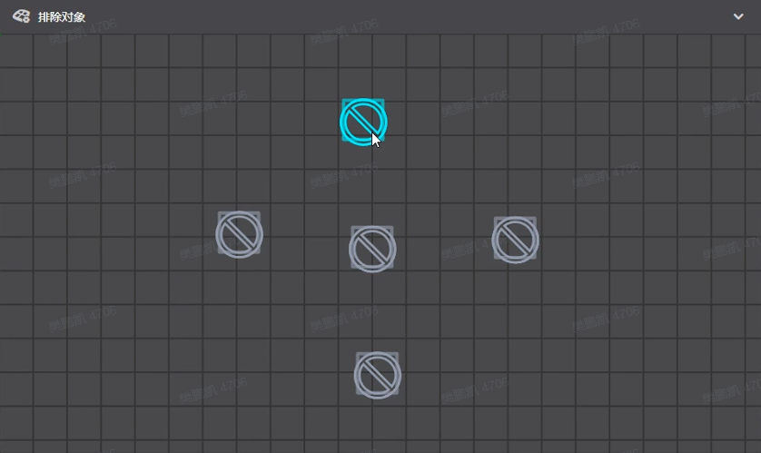
This setting refers to excluding a single object (requires firmware support) during the printing process.
¶ Exact Flow Enable
¶ 2. Exact Flow Enable
It refers to the precise control of the flow rate of the extruded melted consumables. This setting can control the flow rate to the maximum extent, thereby achieving more precise printing. This setting improves print quality.
¶ Enable coasting
¶ 3. Enable coasting
Gliding will replace the last part of the extruded path with an empty path. Bleed material is used to print the last part of the extrusion path to reduce skewing. If this setting is enabled, the nozzle will stop extruding material slightly before closing the wall profile.
The idea is that the nozzle chamber can empty itself on the last stretch of line, which reduces the pressure on the nozzle and allows it to be blocked by the start of the profile. This then creates fewer seams at the beginning of the profile and reduces stringing in subsequent travel movements.
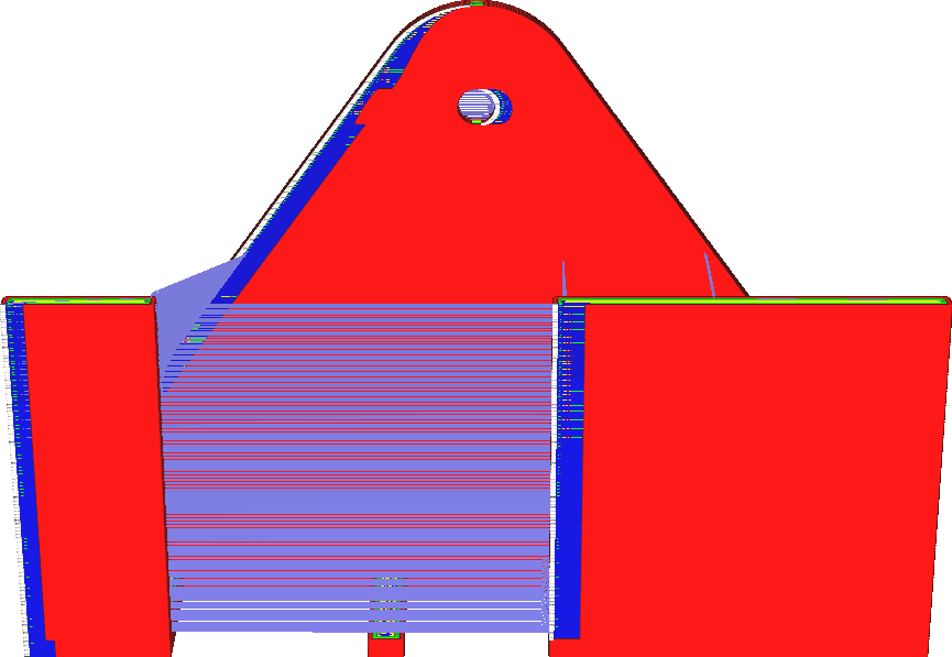
Enable glide to reduce the visibility of wall seams.
If you typically have large fat gaps, enabling this feature can reduce this effect. It basically does the opposite of the outer wall wipe distance, so it's best to try to reduce the wipe before trying to slide. In theory, there will always be undersqueezing from coasting. Whether this is visible in actual printing depends on the circumstances.
For printers using direct drive, glide tends to be more effective. If your printer has a direct drive, you will need to reduce the glide volume to a lower value than when using a Bowden tube or flexible drive shaft because the flow rate will react much faster. With a Bowden feed system, it will also be more difficult to control the amount of slip to effectively reduce the visibility of the seam.
¶ 3.1 Coasting volume
If this volume is not slid, overflow will occur. This value should generally be close to the nozzle cubic diameter.
This setting determines how long the feeder stops feeding before the end of the profile. However, the length of the glide is configured based on the volume of material. It is more closely related to the volume inside the nozzle chamber.

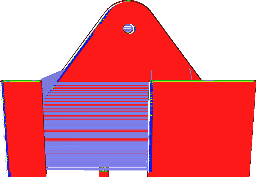
Increasing the glide volume will cause the nozzle to stop further extrusion before completing the contour. As a result, it ends up with more undersqueeze. The purpose of glide is to compensate for spots when contouring is stitched, so increasing the glide volume can compensate for larger spots.
However, increasing the glide volume too much can result in severe under-extrusion at the end of the profile. It can even cause some under-extrusion in anything printed after the outline, since the pressure on the nozzle is still low at that point.
¶ 3.2 Coasting speed
Refers to the moving speed during sliding, relative to the extrusion path. It is recommended to use a value slightly lower than 100%, so the pressure in the bow tube decreases during the coasting movement.
The nozzle no longer extends during taxiing. However, the nozzle continues to travel at approximately the same rate.
This setting allows you to configure the exact rate at which the nozzle continues to travel. Glide speed is configured by a ratio of normal print speed. This means that if the outer and inner walls have different speeds, they will also slide at different speeds.
Typically, gliding is done at a slightly slower speed than normal printing speed to prevent under-extrusion. Reducing the glide speed will reduce the under-extrusion effect naturally caused during glide on the wall, but will increase the under-extrusion effect after the nozzle has moved to print the next structure because the nozzle has been leaking for a longer period of time. Reducing the speed is best combined with reducing the glide volume so that the nozzle does not seep water for too long.
Reducing the speed will also reduce the overall glide effect because the nozzle will also sit on the seam longer. This makes the seams more visible.
¶ Make overhang printable
¶ 4. Make overhang printable
Concept Description: Change the geometry of the printed model to minimize the support needed. Steep overhangs will become shallower. The overhang area will drop to become more vertical.
This setting will transform your model so that it no longer has any overhangs. It will place extra material underneath any overhangs and print as if it were part of the model.
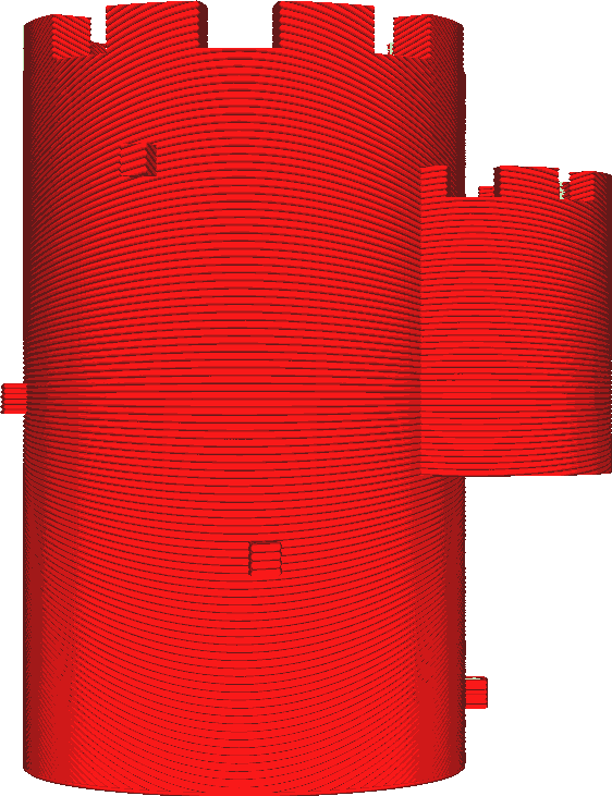
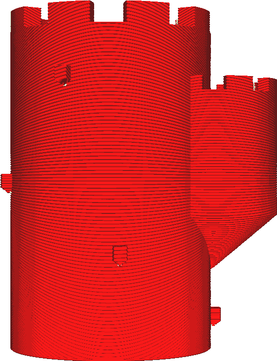
There is material placed underneath all the overhangs that tapers downwards. In many cases, the overhang will tilt toward the object itself. The slope of the overhang's growth into the object is determined by the model angle. This setup can be an easy way to avoid needing any support.
It is particularly effective when printing models with somewhat rough surfaces or embossed sides. These dangling bits often sag and create loose, broken plastic ropes. They may get some support, but this may take a lot of printing time and still leave some scarring.
If this setting is enabled, the overhang will be smoothed towards the model. It looks like that's how it's printed. If the overhang protrudes from the body further than its width, some overhangs in the form of lines may still result. This happens because the protrusion then shrinks to infinitesimal thinness, causing it to disappear. If this happens, you may consider whether you still need printing support.
In the image above, this happens to the small piece on the side of the tower, but it's so small that a simple bridge would probably allow it to hang nicely.
¶ Use Adaptive layers
¶ 5. Use Adaptive layers
Conceptual description: Refers to calculating the layer height based on the model shape.
Adaptive layers will locally adjust the printed layer thickness based on the surface characteristics of the model to optimize print time and print quality. Where the slopes are shallow, these layers become thinner, and where the walls are steep, the layers become thicker. The idea is to print as quickly as possible but still print detailed information when needed.
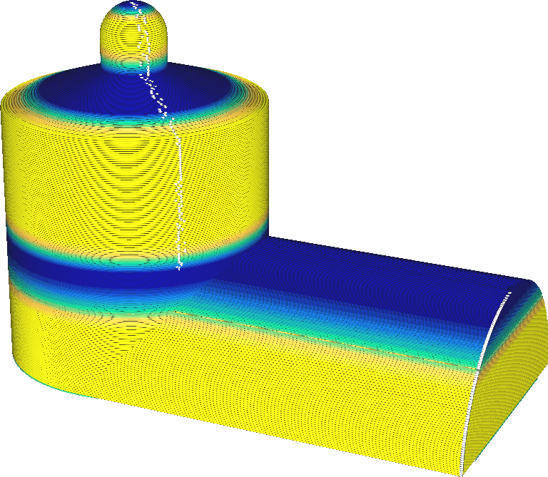
Adjust the layer height so that the horizontal distance between layer edges remains constant. Shallow surfaces result in large horizontal displacements and small vertical displacements, thus producing small vertical displacements to keep the horizontal displacement constant.
For steep surfaces, the horizontal displacement is small and the vertical displacement is large, so a large vertical displacement is required to keep the horizontal displacement constant. Therefore, the morphological effects of the layers remain constant. The maximum distance between two adjacent layers is kept at a constant distance set by the threshold. If the model has both shallow and steep surfaces at the same height, the layer thickness is taken to be the smaller of the layer thicknesses. This sometimes makes the floor heights unnecessarily small because there is a horizontal surface next to it. This can be seen in the screenshot above, and also at half the height of the silo on the left.
To improve print quality, adaptive layers will be severely restricted. The layer height is not allowed to deviate from the original layer height setting by more than the specified maximum change. The difference in layer height between two adjacent layers must also not exceed a certain step size. This property causes a gradual transition in layer thickness, rather than suddenly cutting it in half from one layer to the next.
Adaptive layers can significantly reduce print time without reducing print quality, and in some cases can even improve it. The effect of adjusting layer thickness is huge. In most cases, the print time will be significantly reduced due to the thicker layers used when the model is vertical.
Topographical effects are also reduced because the layers are closer together in the horizontal direction.
However, this feature also brings many problems.
• When changing layer heights, you often need to adjust some other settings, such as nozzle temperature. Adaptive layers don't automatically adjust these either. This can result in suboptimal print results, for example: Overhanging sections perform better at lower printing temperatures.
• If you change the layer height of a small feature in a small part of the layer over the entire layer, the banding will be visible in the rest of the layer. • The vertical distance will also be adjusted unintentionally. This may negatively affect print quality. For example, the top/bottom thickness will usually be lower because CrealityPrint will leave the top layer settings at true values and the layers will become thinner. This may lead to pillows.
Affected settings that may no longer be correct include:
• Number of top layers
• Number of bottom layers
• Progressive fill steps
• Support Z Distance
• Top support
• Bottom support
¶ Angle of Slope Slice
¶ 6. Angle of Slope Slice
Concept description: Refers to the slicing angle for the sloped part of the printed product.
¶ Rotation Axis of Slope Slice
¶ 7. Rotation Axis of Slope Slice
Concept description: refers to the slicing rotation axis when slicing the slope part of the printed product.