We’re excited to announce the official release of Creality Print 6.3.0! This version focuses on enhancing stability, improving time estimation accuracy, and delivering a smoother overall user experience. With these updates, users can look forward to a more reliable and efficient printing workflow.
¶ 1. Print Algorithm Optimization
¶ 1.1 Top surface path
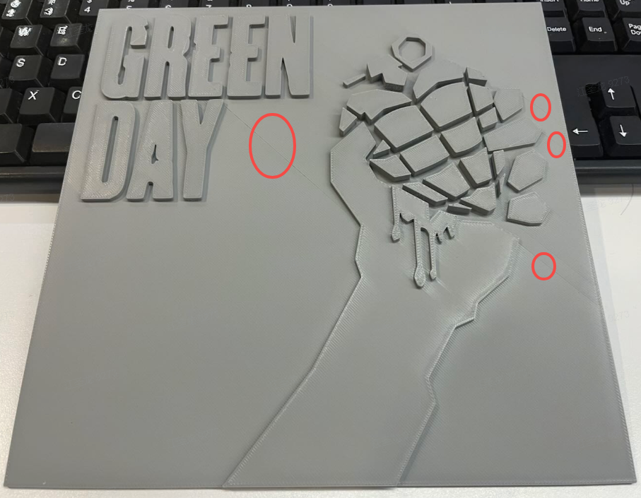
In scenarios such as printing embossed reliefs, it is common for the top surface path to be too complex to complete in a single continuous pass. When the path pauses in one area and then returns to print, the already printed lines have fully cooled and shrunk. This reduces adhesion between the previously extruded filament and the newly extruded filament, resulting in visible gaps on the surface.
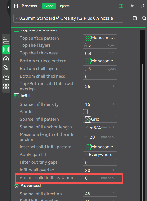
Optimization Solution: A new feature — Anchor solid infill by X mm (thanks to contributions from @SuperSlicer) has been added. By default, this feature is disabled (parameter set to 0). Users can enable it and set the parameter value according to the model’s characteristics.
|
|
|
Example: Setting the value to 0 mm will cause large flat top surfaces to have many path jumps, resulting in visible shrinkage lines on the top surface.
Setting the value to 50 mm allows the entire large top surface to be printed in a single continuous path, eliminating visible seams.

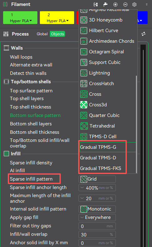
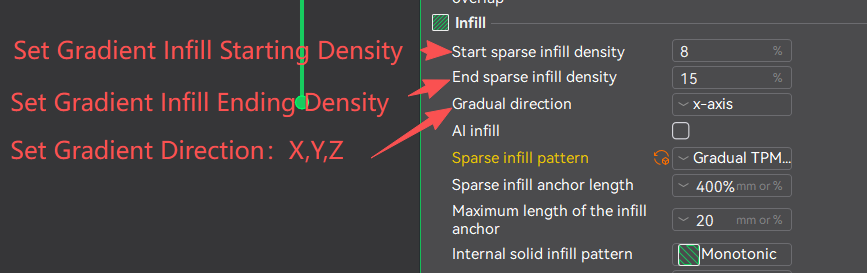
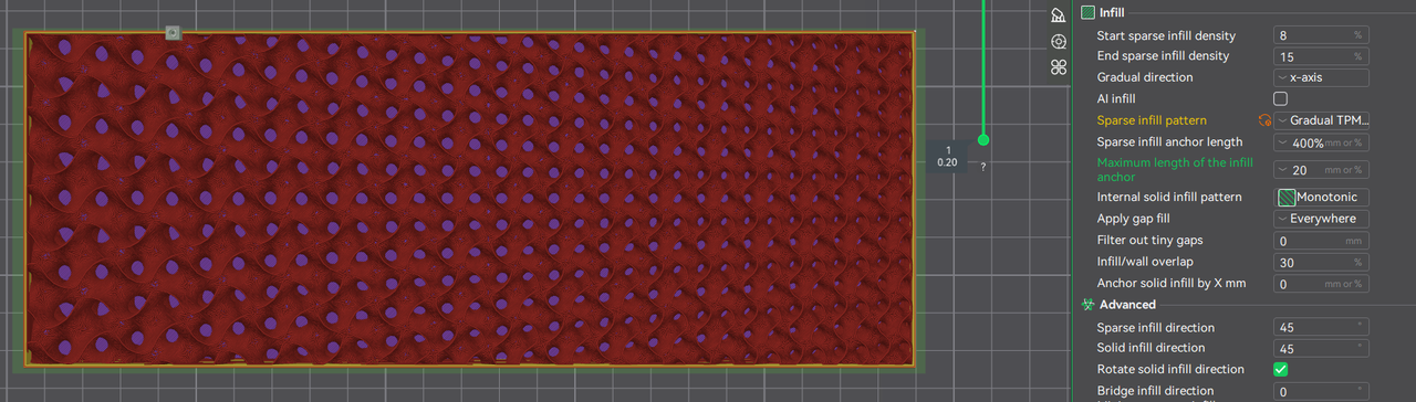
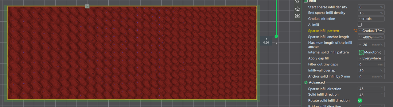
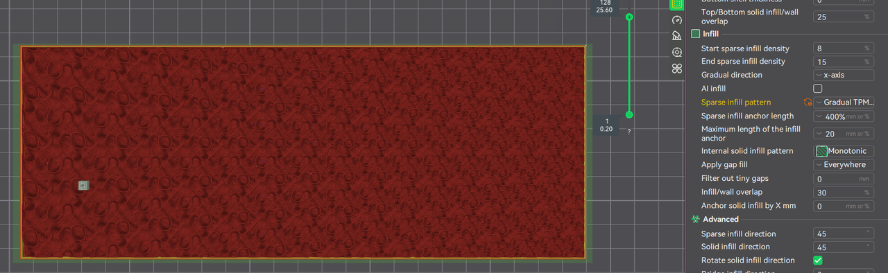
¶ 1.2 Gradual Infill
Currently, most FDM printing infill methods use a uniform density. In certain cases where adjusting the center of gravity is necessary to improve the stability of the printed model — for example, objects that are top-heavy (such as large-headed figurines) — using uniform infill density can waste material and result in instability. For objects that are large at one end and small at the other, it is desirable to increase infill density in the smaller sections to enhance local structural strength, while maintaining higher density in the larger head section.
Driven by this scenario, three new TPMS infill types have been developed to enable gradient infill, allowing infill density to vary along the printing direction to improve stability and material efficiency.
 |
 |
 |
¶ 2. Usability Improvements
¶ 2.1 Height(Weight) Limit Speed and Acceleration Optimization
The taller a model is, the higher its center of gravity becomes, making vibrations more likely to be amplified. With the new Height(Weight) limit speed and acceleration, you can set specific thresholds near the top or within designated height ranges. When these thresholds are reached, the printer automatically reduces speed and acceleration to the configured values, helping to minimize vibration and oscillation. This improves the print quality of tall towers or slender structures, enhances the stability of high models, and increases overall print success rates.
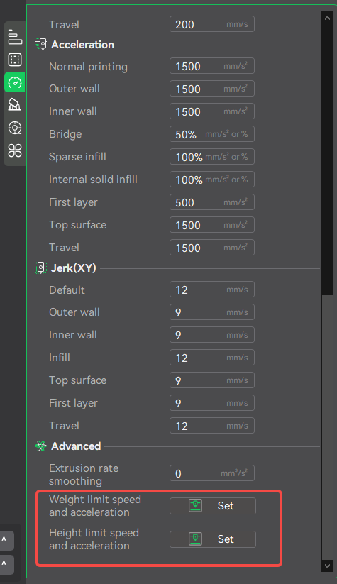 |
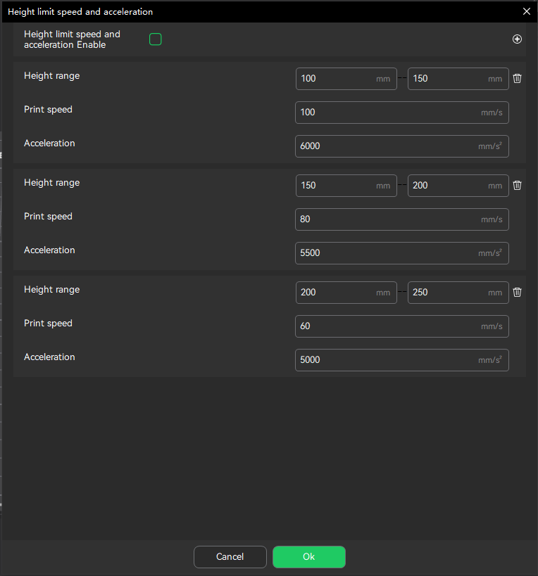 |
¶ 2.2 Parameter Visibility Optimization
To enhance printing success rates and equipment safety, this update has restricted editing access to a limited number of high-risk or system-controlled parameters by hiding or locking them. Key parameters across printer settings, process configurations, and material properties—including hardware-related safety limits, firmware-managed thresholds, and material-/model-specific calibration values—will now be automatically applied based on active presets. This prevents misconfiguration issues such as clogging or mechanical damage, while maintaining full creative freedom. The goal is to deliver a more intuitive and streamlined user experience.
In this update, parameters such as speed, acceleration, and jerk limits are displayed as non-editable fields in the printer settings interface. The system now dynamically clamps these values based on the device’s hardware capabilities to prevent lost steps, ringing artifacts, and excessive mechanical wear.
|
|
|
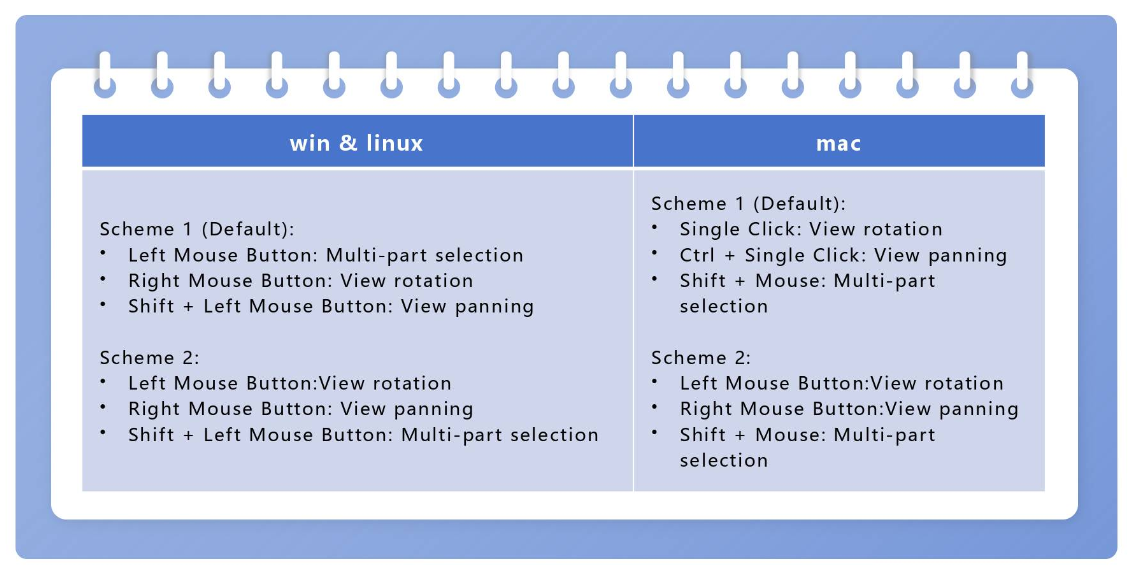
¶ 2.3 Hotkey Optimization
Dual hotkey schemes have been added for three frequent operations: Select objects by rectangle, Rotate view, and Pan view. Users can switch between scheme 1 (default) and scheme 2 at any time. Thanks to @Roberto and @Joerandazzo85 for the suggestions.
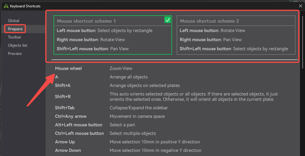
Windows and Linux share the same hotkeys; macOS uses a different configuration.
¶ 3. Performance and Efficiency Improvements
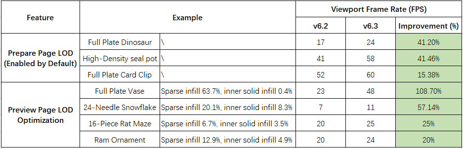
In this update, we focused on improving the rendering efficiency of the Prepare and Preview pages. One of the core enhancements is the introduction of LOD (Level of Detail) technology in the FDM view. LOD automatically adjusts the rendering detail based on the distance between the model and the camera: finer details are preserved at close range, while simplified geometry is used at a distance. This approach maintains visual quality while significantly boosting performance, ensuring a smoother experience even with complex models or full-plate printing.
¶ 3.1 Prepare Page Rendering Enhancements
Introduced LOD mode, specifically optimized for single-color model scenarios. Frame rates improve by approximately 15%–40%, effectively reducing lag during operations.
¶ 3.2 Preview Page Performance Optimization
Enhanced LOD optimization for the preview view, particularly when “Simplified Mode” is turned off. Frame rates improve by about 20%–100%, with noticeable smoothness improvements in scenarios involving large infill structures.
¶ 4. Bug Fixes
- Resolved slicing crashes for certain model files.
- Fixed application crash occurring after user login, thanks to @HYorb.
- Corrected WebView rendering issues causing blank Send Page and Device List screens, thanks to @stefanmocanu668 and @Peter.
- Fixed incorrect color display in model previews for overlapping parts.
- Resolved crashes triggered when enabling Top Surface Ironing.
- Fixed preset mismatch issue for the Sermoon D3 Pro on the Send Page, thanks to @Juan Godoy.
- Corrected synchronization errors in device page card information, thanks to @L.
- Fixed color bleeding issues for overhangs in multi-color prints.
- Resolved scaling errors where hole dimensions were incorrectly adjusted after model scaling, thanks to @chris.samuelson.
- Fixed inability to close the application after slicing large files on macOS, thanks to @Franck.
- Corrected issue where flow calibration adjustments did not generate G-code.
- Fixed Overhang Classic Mode settings not retaining values after software restart.
- Resolved text rendering anomalies causing black blocks in the interface, thanks to @hal.rabbs and @John Mooney.
- Fixed missing CFS (Creality Cloud Service) information when connecting to a printer, thanks to @newtd.
- Corrected wipe tower position shift occurring after filament changes.
- Fixed incomplete G-code text display in the Preview panel, thanks to @tovi.
- Added prompts in the top toolbar to guide users when manual support placement is selected.
- Optimized font rendering and display clarity on the Preparation Page, thanks to @newtd.
- Fixed text display issues on the platform when using the Japanese language interface, thanks to @sunstella.
- Corrected multiple translation errors in German and Japanese localizations, thanks to @Toni Hofmann and @鬼塚安登.