¶ Feature Overview
In multi-material 3D printing scenarios, the interlayer bonding strength between different filaments often varies. Beam interlocking works by generating additional micro-bridges or beam-like structures at the boundary between two materials, allowing different filaments to physically interlock and achieve a more reliable connection.
During standard slicing, multi-material models are divided into separate regions and assigned to corresponding printheads or filament slots. However, combinations like TPU and PLA, while each prints well on its own, may suffer from insufficient adhesion between them, causing the finished part to delaminate along the seam under slight stress. The following sections detail the benefits and configuration of this feature.
¶ Feature Benefits
¶ Enhanced Bonding Between Different Material Types
Beam interlocking constructs bridging structures at the boundaries between rigid and flexible materials. Through the dual action of mechanical anchoring and thermal fusion bonding, it significantly reduces the probability of delamination or cracking when the part is bent or impacted.
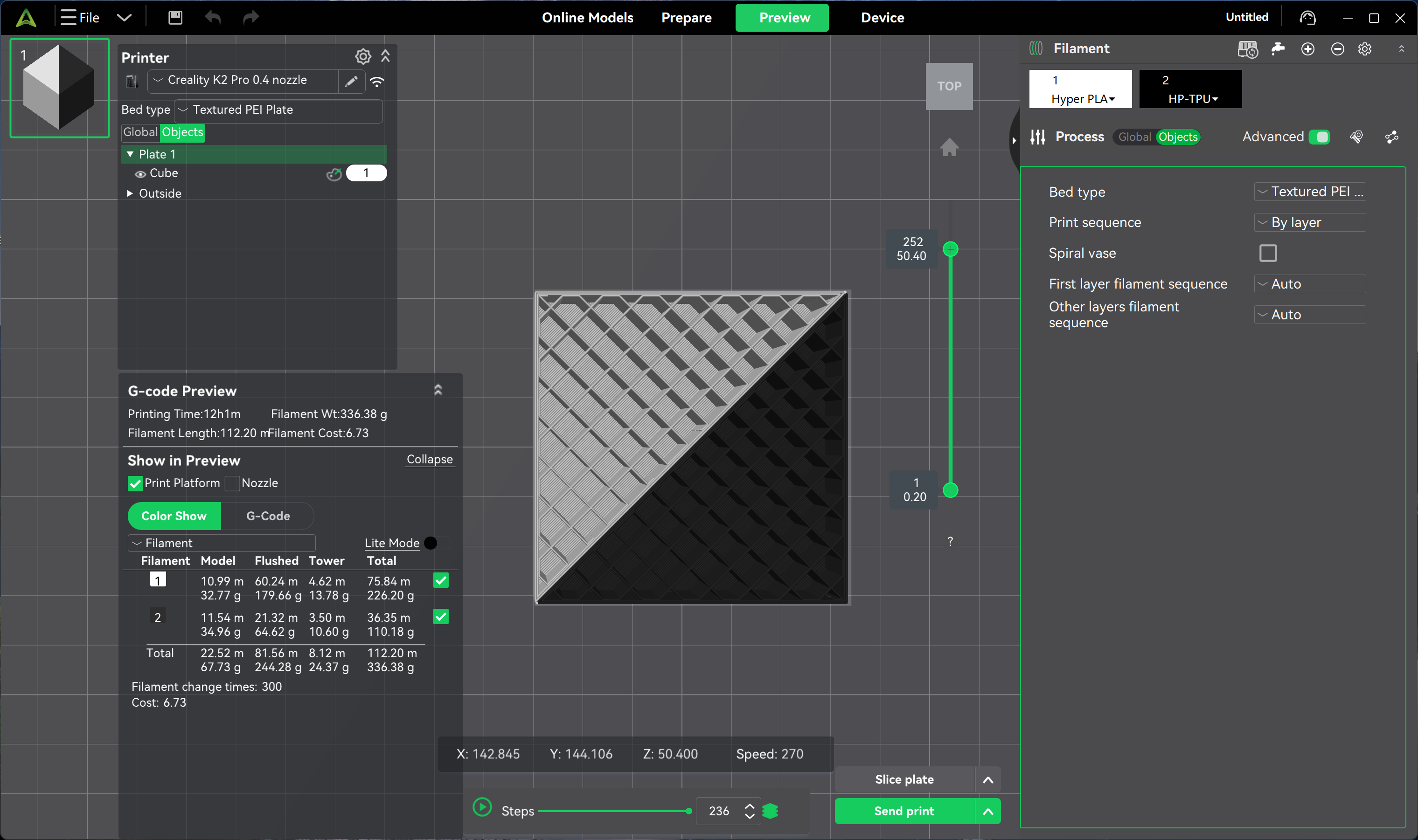
Structural comparison before and after application:
Effect after enabling beam interlocking:
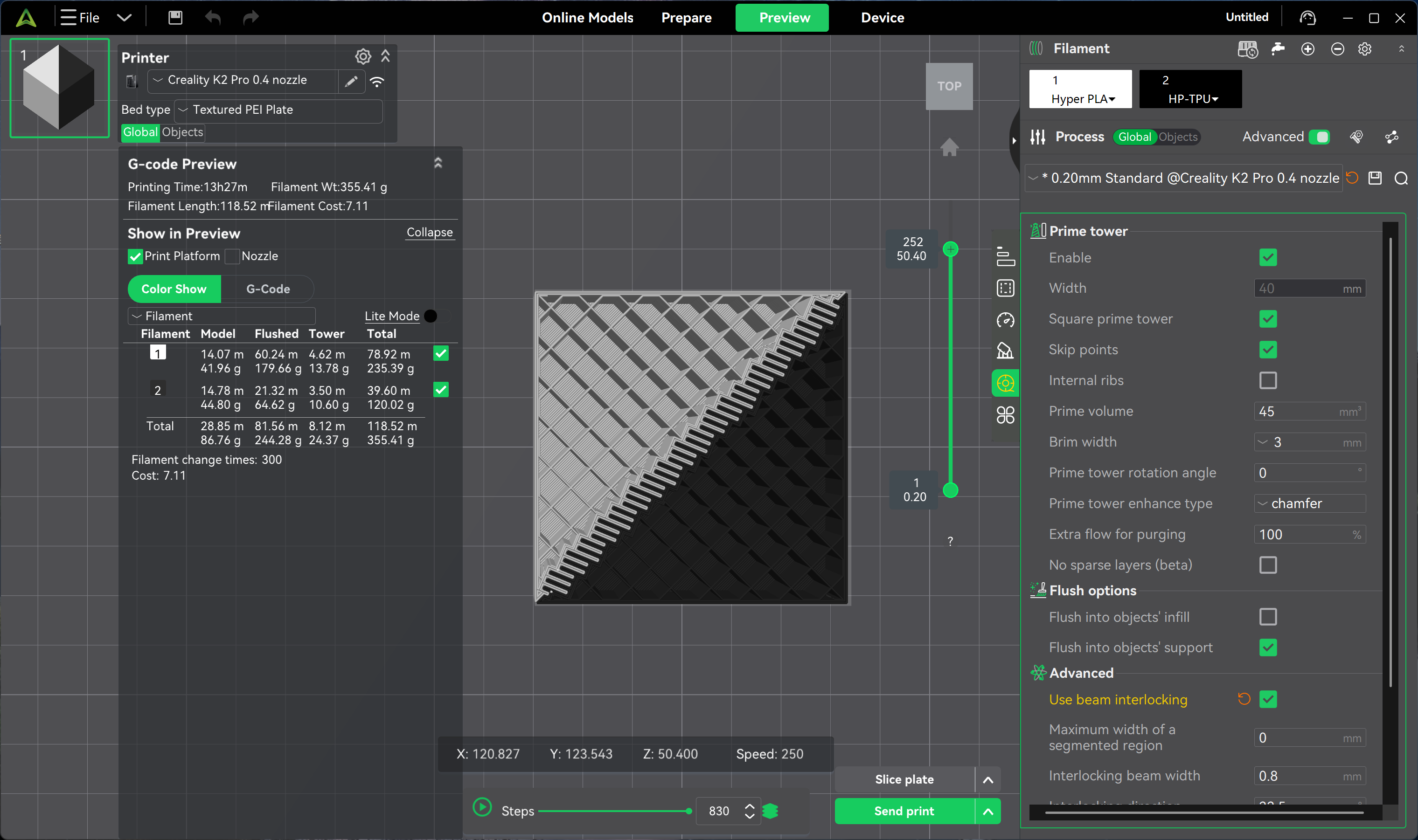
As seen in the images above, additional connecting structures are added at the boundary regions.
Take a daily-use 3D-printed phone case as an example: without beam interlocking, the TPU border may gradually peel or curl away from repeated insertion and removal of the phone. With this feature enabled, the flexible TPU and rigid PETG shell form a mechanical interlock, making the overall structure more wear-resistant and fatigue-resistant.
¶ Enhanced Part Durability
During multi-material printing, intermittent extrusion from the nozzle can create localized weak points. Beam interlocking reinforces these critical nodes, allowing the finished part to withstand repeated bending and long-term loading, making it suitable for high-frequency use cases such as tool grips and wearable accessories.
¶ Simplified Assembly Design
For functional structures such as snap-fits, hinges, and flexible joints, beam interlocking can replace adhesives or fasteners, enabling one-piece printing. Designers no longer need to deliberately avoid specific structures due to material incompatibility, greatly expanding the design space for multi-material models.
¶ Optimized Appearance Seams
Beam interlocking allows transition regions between different materials to bond more tightly, effectively minimizing seam marks and improving surface appearance. This characteristic is particularly important for display-grade models, cosplay props, and aesthetic parts.
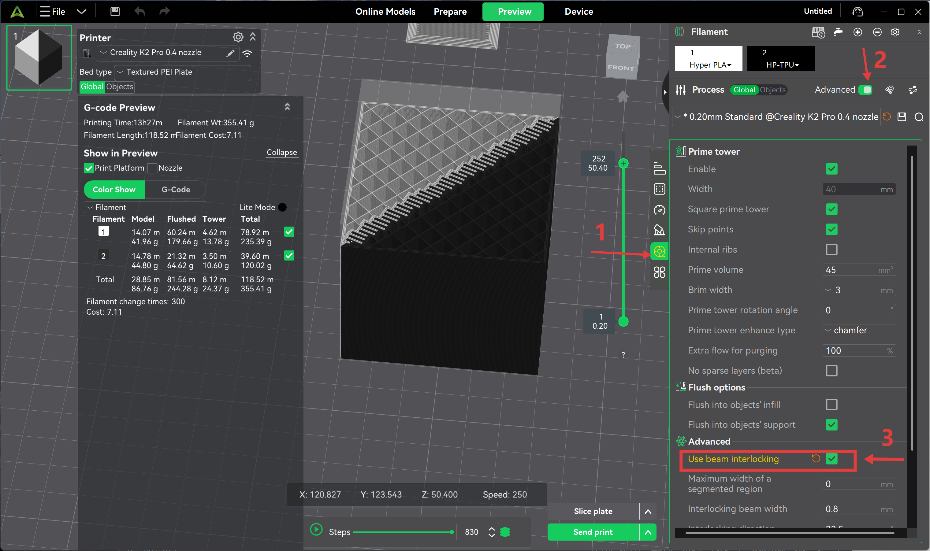
¶ Parameter Configuration Path
To enable beam interlocking in Creality Print:
Process → Material → Advanced Options → Enable Beam Interlocking
¶ Parameter Details
¶ Beam Width
Defines the thickness of a single interlocking beam (default 0.8 mm). Increasing this value enlarges the contact area and mechanical bite force, but consumes more internal space; if set too large, it may interfere with fine details.
For small parts, it is recommended to set this between 0.4–0.8 mm to balance detail fidelity and connection strength.
The following example uses a PLA / PETG / TPU combination: PETG and PLA are both rigid materials but differ in toughness, while TPU is highly elastic. The beam width must be set appropriately to balance rigidity and flexibility.
Keeping the default 0.8 mm yields good results. If reduced to 0.2 mm, the bonding surface becomes too fragile, and the TPU layer may even detach.

Conversely, increasing the width to 1.0 mm noticeably thickens the beams, creating a stronger connection, but the spacing between adjacent beams will also increase accordingly.
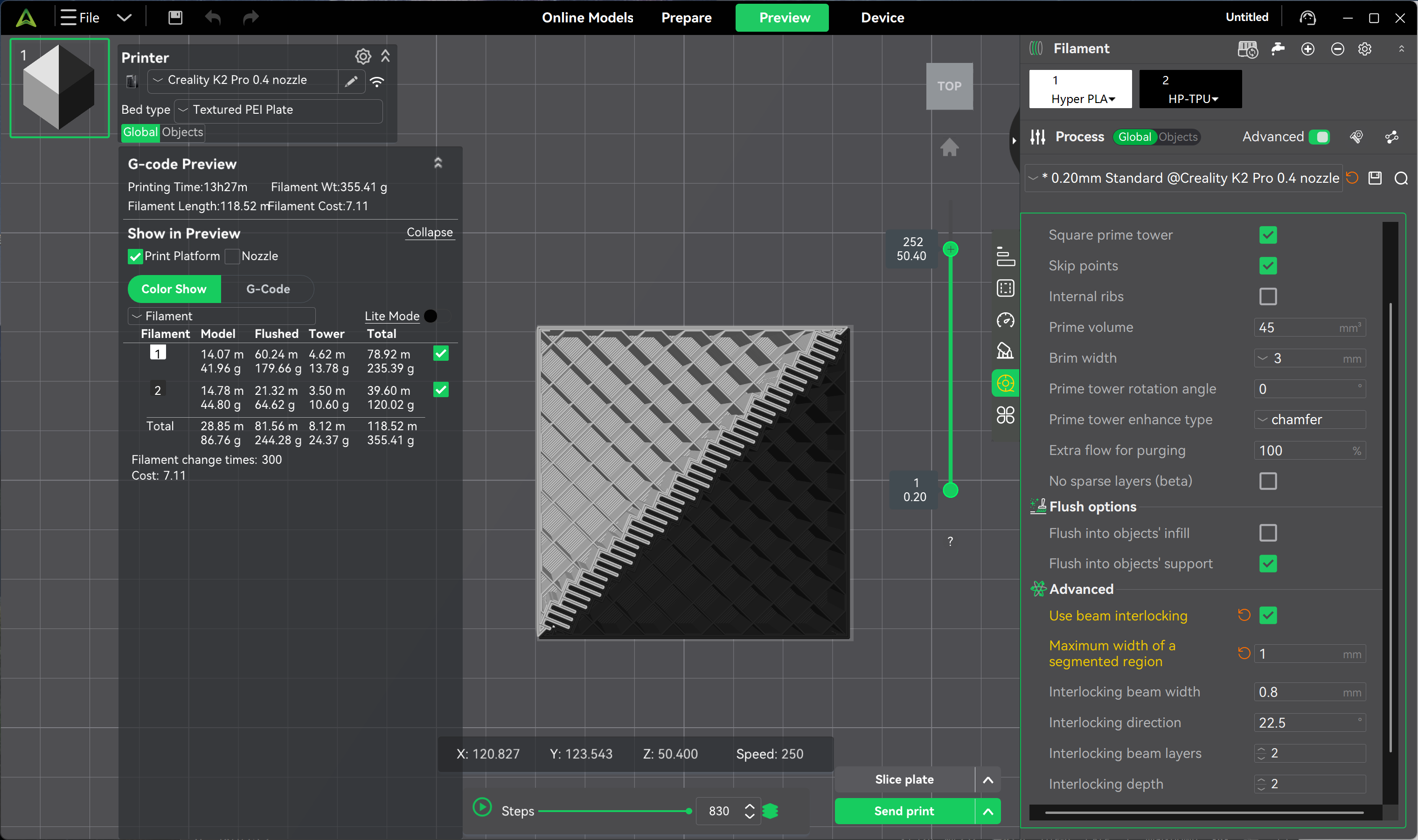
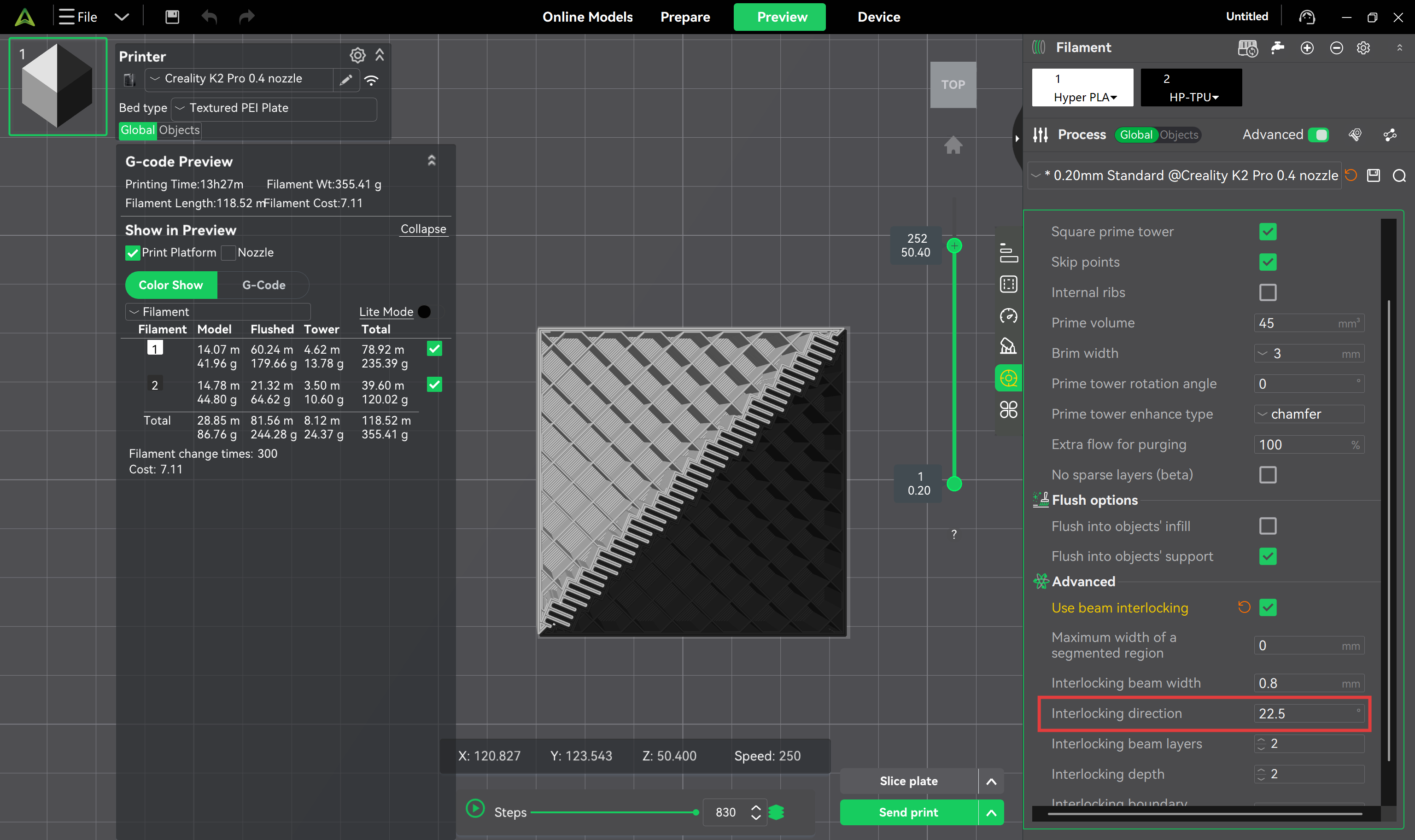
¶ Interlocking Direction
Controls the generation angle of the interlocking beams, defaulting at 22.5°. This angle distributes the beams diagonally rather than purely horizontally or vertically, helping to reinforce boundaries while preserving the deformation capability of flexible materials.
At the default angle, the TPU middle layer bonds firmly with the upper and lower rigid shells without affecting normal bending during use:
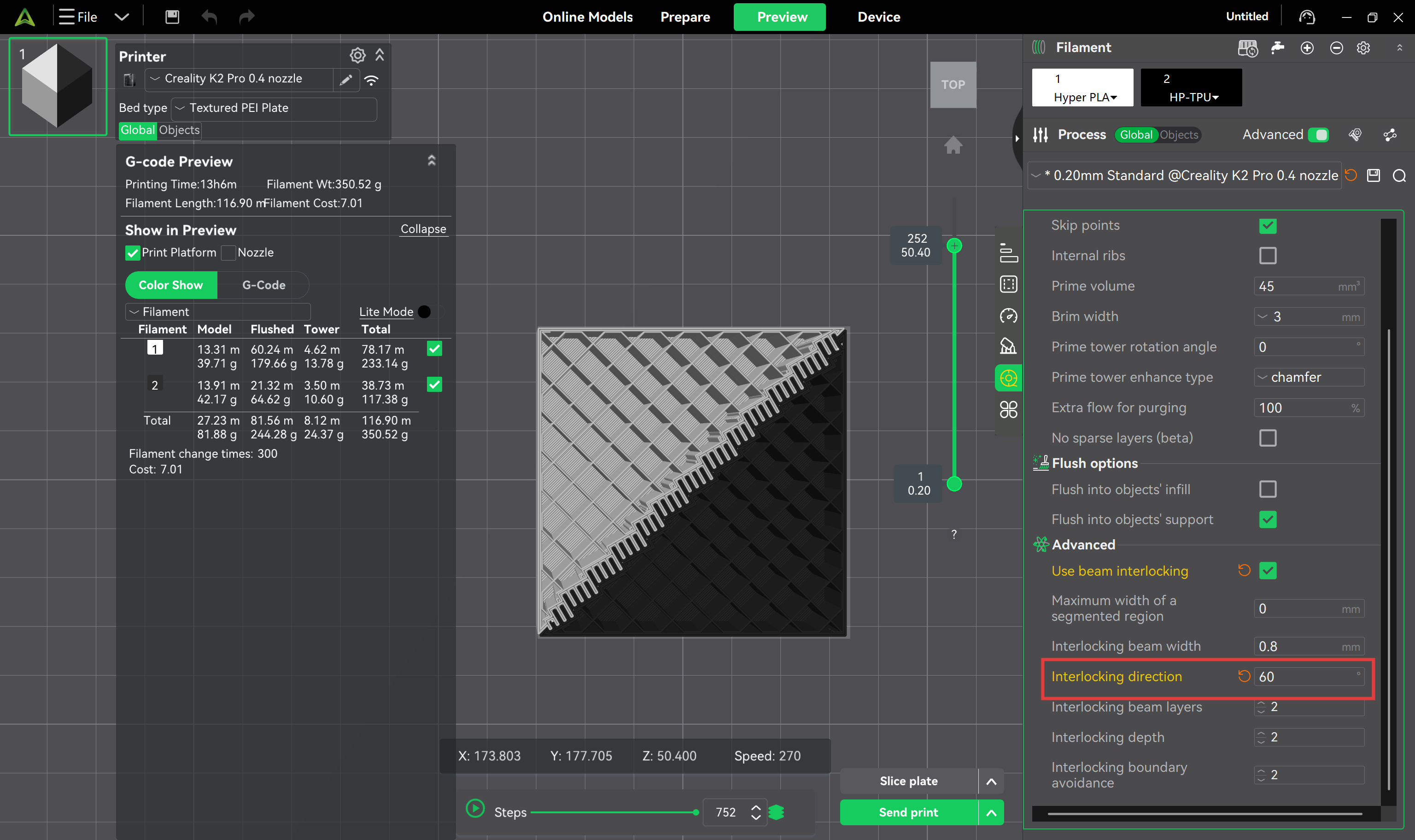
Effect after adjusting to 60°:
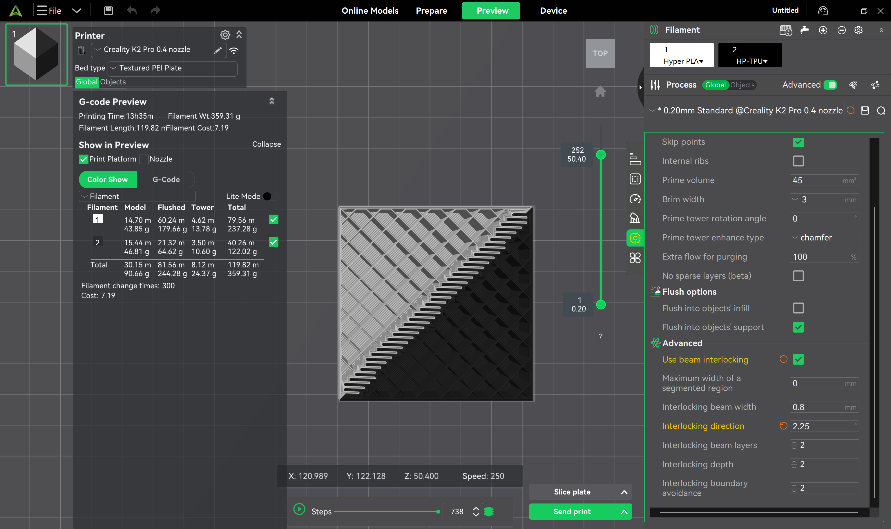
Effect after adjusting to 2.25°:
¶ Beam Layers
Determines the stacking height of the interlocking beams along the Z-axis.
Fewer layers → tighter structural bonding, but reduced printing stability and higher risk of defects.
More layers → slightly weaker bonding, but a more stable and reliable printing process.
If there are no special requirements, it is recommended to keep the default value of 2.
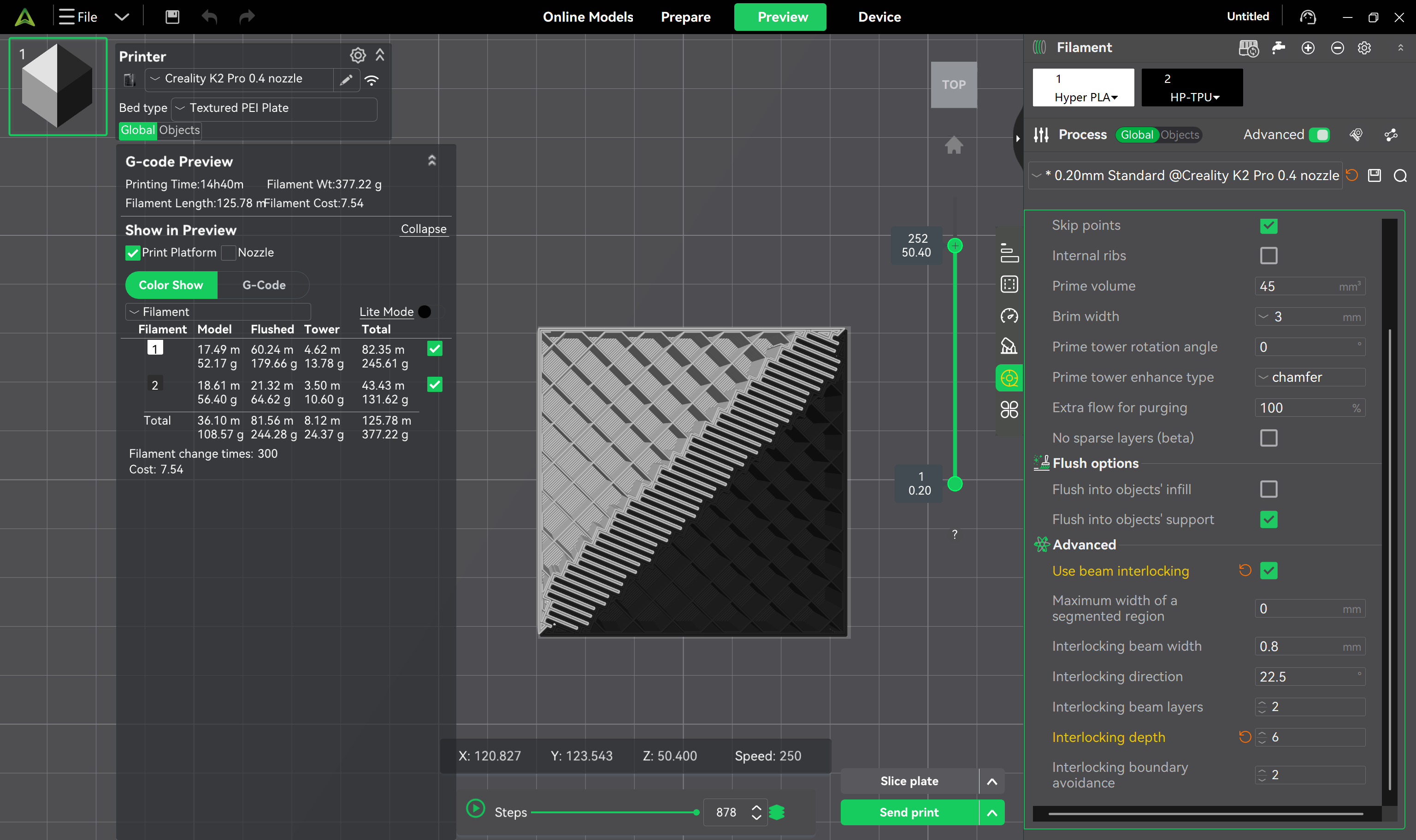
¶ Interlocking Depth
Refers to the distance the interlocking beam extends inward from the material boundary, with a default value of 2.
Increasing this value (e.g., to 6) → the beams penetrate deeper into more layers of material, creating a stronger anchoring effect.
Keeping the default value → provides stable bonding performance in most scenarios.
Note that adjusting the depth may increase the frequency of filament changes during slicing.
Effect with depth set to 6:
¶ Boundary Avoidance
Sets the clearance distance between the interlocking beams and the model's outer contour.
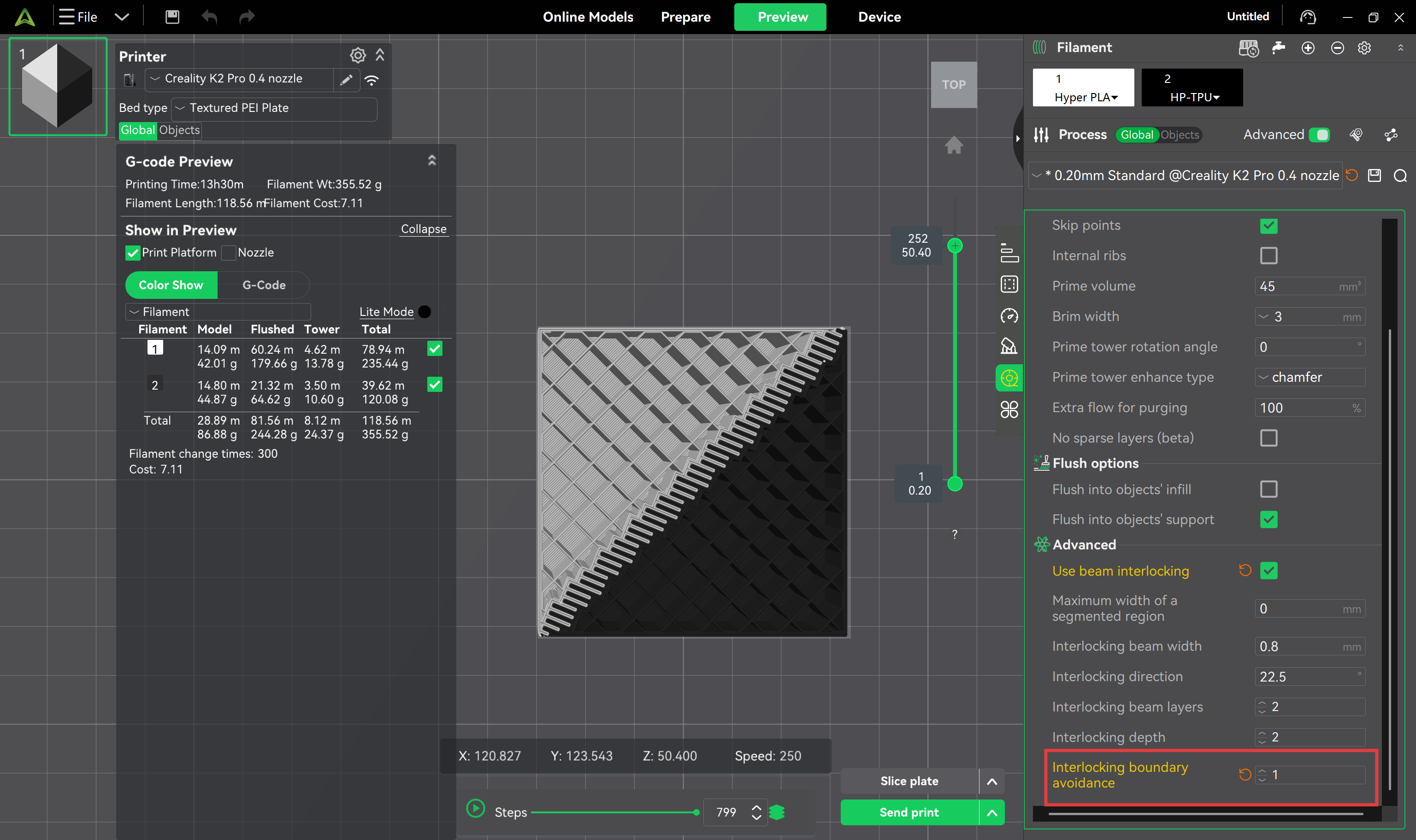
Set to 1 → beams stay close to the shell, providing high structural strength while maintaining acceptable surface quality.
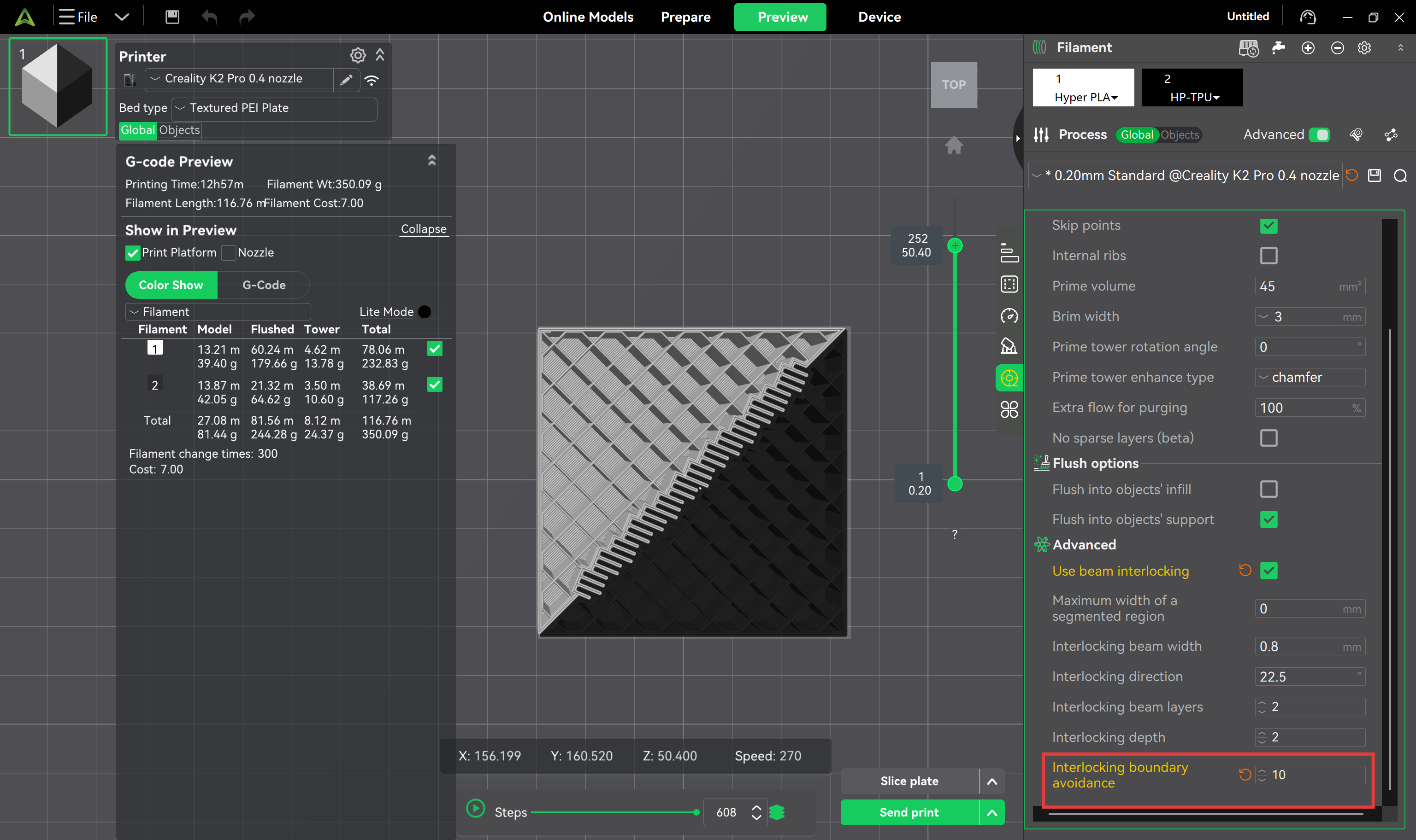
Set to 10 → beams retract significantly inward, resulting in a smoother and cleaner outer wall, but edge structural strength will be somewhat reduced.
Clearance = 1 (prioritizing structural strength):
Clearance = 10 (prioritizing surface quality):
¶ Recommendations
-
Verify wall thickness and internal space: Before enabling beam interlocking, ensure the model has sufficient internal space to accommodate the beam structures, and that the outer wall thickness is adequate to maintain overall strength. For thin-walled or high-detail parts, appropriately reduce the number of beam layers or lower the penetration depth to avoid damaging critical features.
-
Orient the model properly: The part's placement angle should align with the beam interlocking direction to achieve optimal mechanical bonding.
-
Pay attention to material pairing: Prioritize material combinations with good compatibility; for example, TPU and PETG bond well together. However, TPU and standard PLA usually have poor adhesion and are prone to delamination at corners, so direct pairing should be avoided when possible.
-
Conduct test prints first: Before formally printing large or critical parts, it is recommended to produce small test samples to confirm whether the beam interlocking parameters match the current materials and model structure.