¶ Chapter 1. Interface and Basic Operations
PioNext BOX is a slicing software specifically designed for dental photopolymerization 3D printing, offering a one‑stop workflow from model import to slice export. The interface is divided into four areas: top menu bar, left toolbar, right parameter panel, and bottom status bar, all working together to complete printing tasks.
¶ 1.1 Top menu bar
The top menu bar contains four major functional modules: File, Edit, View, and Settings.
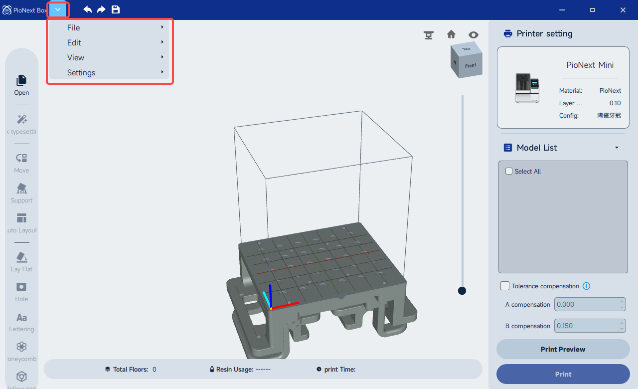
¶ File menu
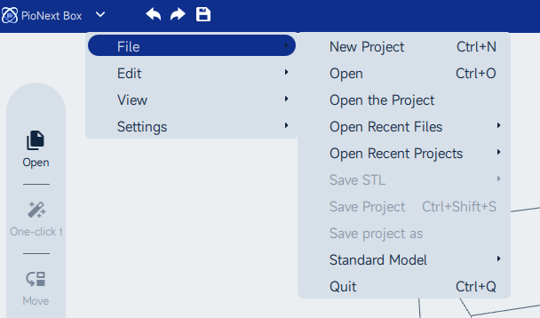
- New Project : Create a blank print project
- Open: Import local STL model file
- Open the project : Import a previously saved project file (including all settings such as models, print parameters, layout, etc.). No need to reconfigure; you can re‑edit or slice directly.
- Open Recent Files: Quickly open recently used STL models
- Open Recent Projects : Quickly open recently edited projects
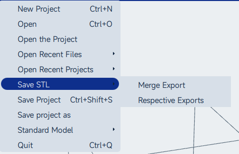
- Save STL: Export model to STL format
- Merge Export: Export multiple models as a whole into a single STL file
- Respective Exports: Export each model separately as an STL file.
- Save Project: Save the current project file, preserving all current operations (models, parameters, layout, etc.). There is a corresponding Save Project button in the top menu bar.
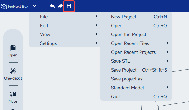
- Save Project As: Save the project as a new file, allowing you to modify the save path and file name to avoid overwriting the original project
- Standard Model : Load the built-in standard test model
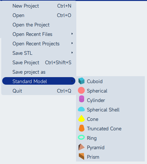
- Quit: Close the software
¶ Edit Menu
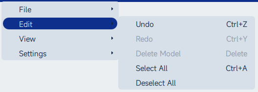
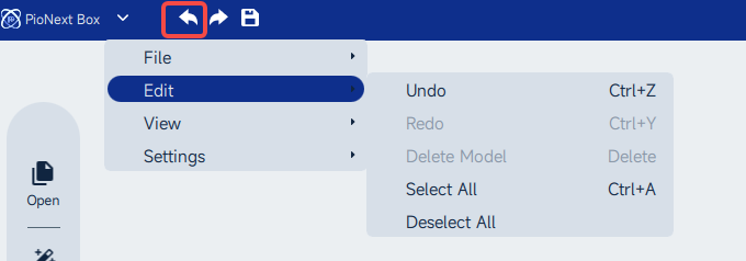
- Undo: Undo the last operation, with a corresponding button in the top menu bar
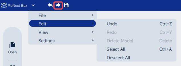
- Redo: Redo the undone operation, with a corresponding button in the top menu bar
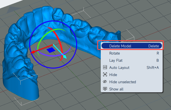
- Delete Model: Delete the selected model
- You can also right-click after selecting the model to bring up the menu and choose Delete
- Or directly press the Delete shortcut key on the keyboard to quickly delete, making the operation more convenient and efficient.
- Select All: Select all models in the current scene
- Deselect All: Cancel all currently selected models
¶ View Menu
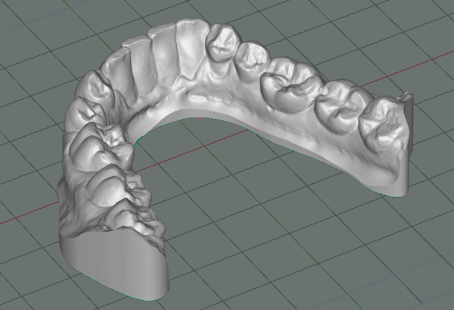
- Show Model Face: Display models as solid faces, giving an intuitive view of appearance, contours, and surface details. Ideal for checking damage or defects and for daily editing.
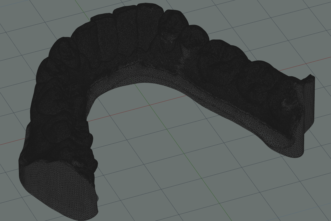
- Show Model Line: Display models as lines, facilitating inspection of internal structures, hollow areas, and support distribution.
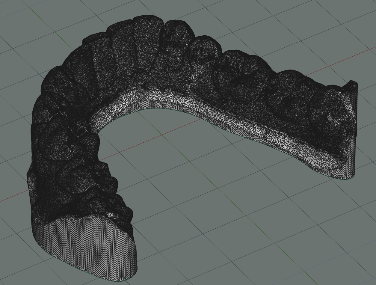
- Show Model Face Lines: Display both faces and lines simultaneously.
¶ Settings Menu
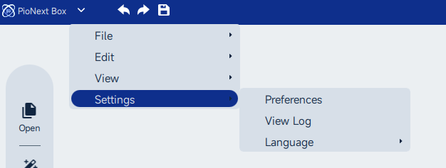
- Preference: The core settings entry, containing four key setting items.
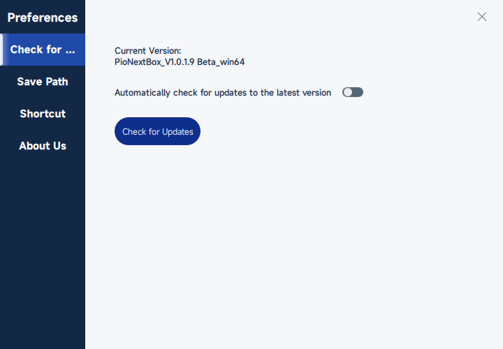
- Check for Updates: Check the current software version. For whether an update is needed, please consult the PioCreat 3D after‑sales team.
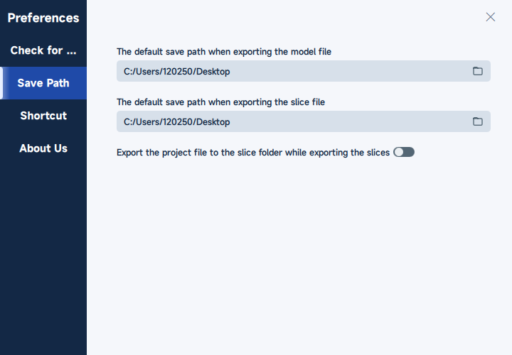
- Save Path: Set the default save location for files
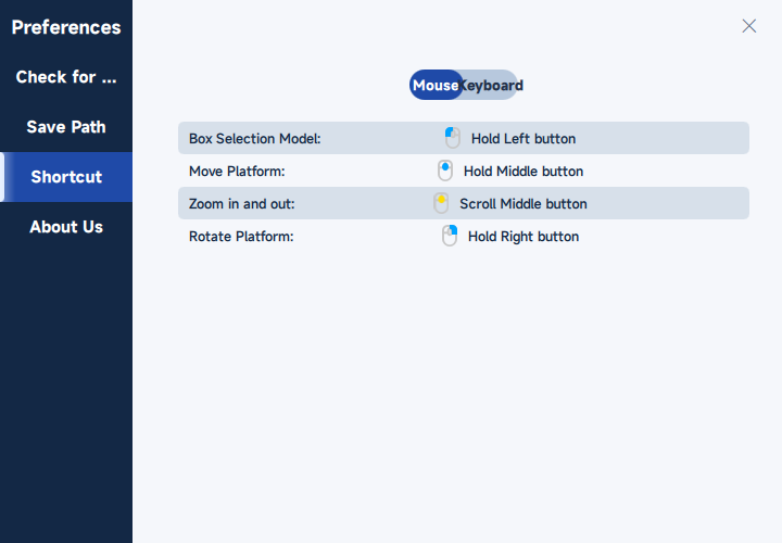
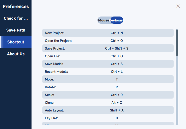
- Shortcuts: View all current software shortcuts. The software currently does not support modifying shortcuts.
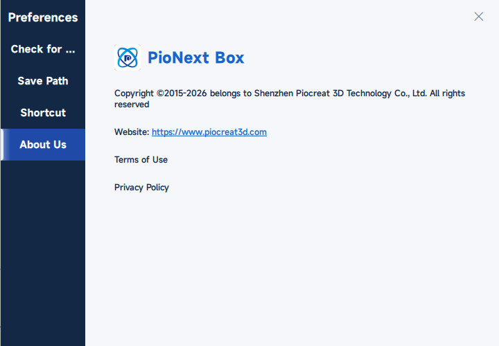
- About Us: View software version and copyright information.
- Check for Updates: Check the current software version. For whether an update is needed, please consult the PioCreat 3D after‑sales team.
- View Log: View system operation logs. In case of print failure, software crash, etc., logs can help troubleshoot the cause.
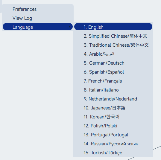
- Language: Switch the software interface language.
¶ 1.2 Mouse and Viewpoint Operations
¶ Right Function Area
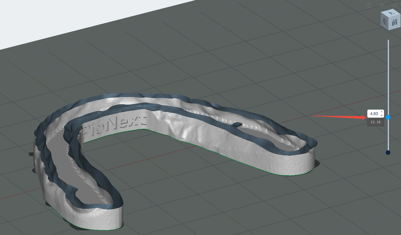
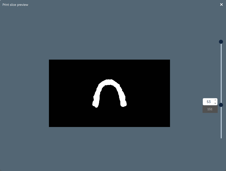
- Right‑side Slider: Preview the sliced effect layer by layer, viewing the printing structure of each layer.
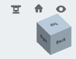
- Top-right perspective cube: Click the corresponding face to quickly switch to Front, Back, Left, Right, Top, Bottom, or Orthographic view.
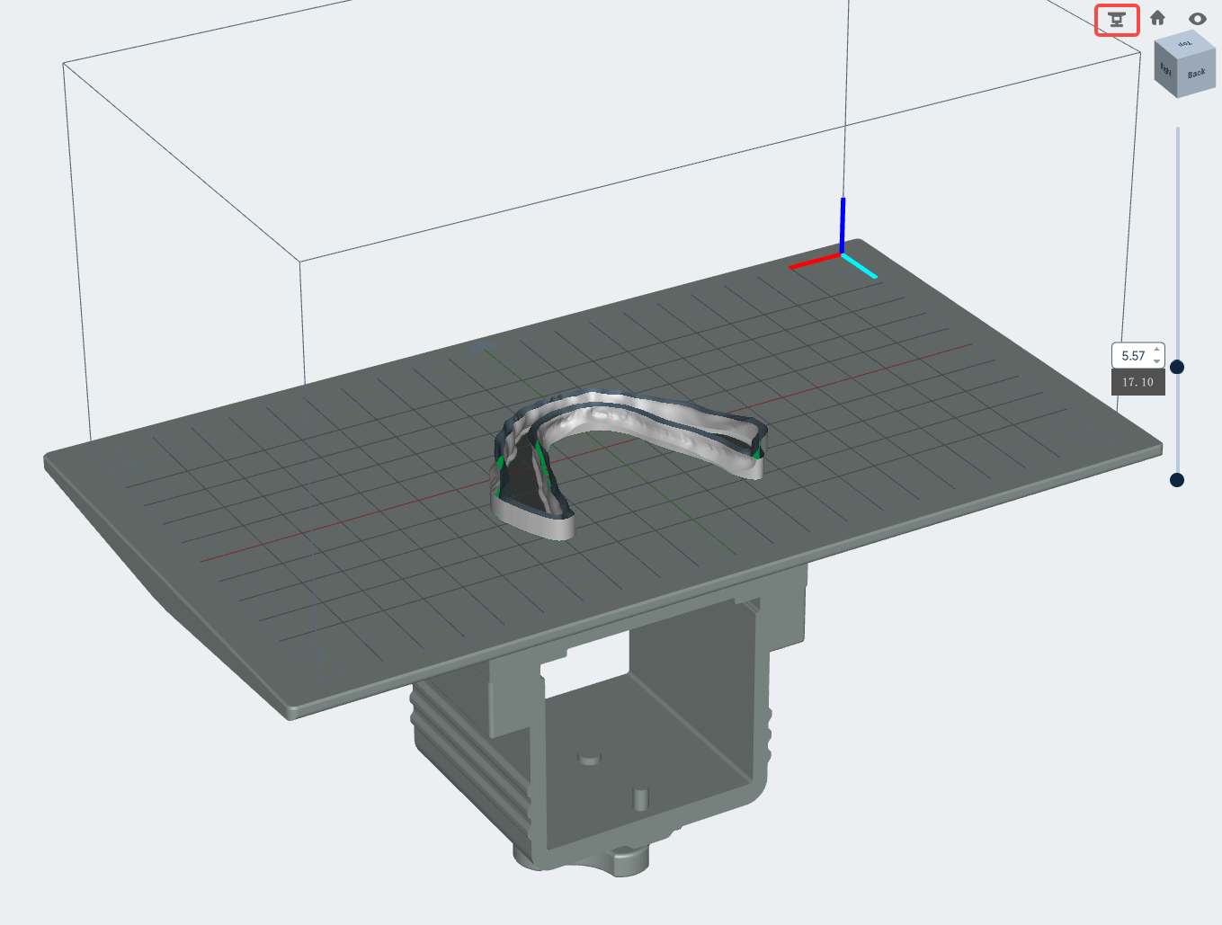
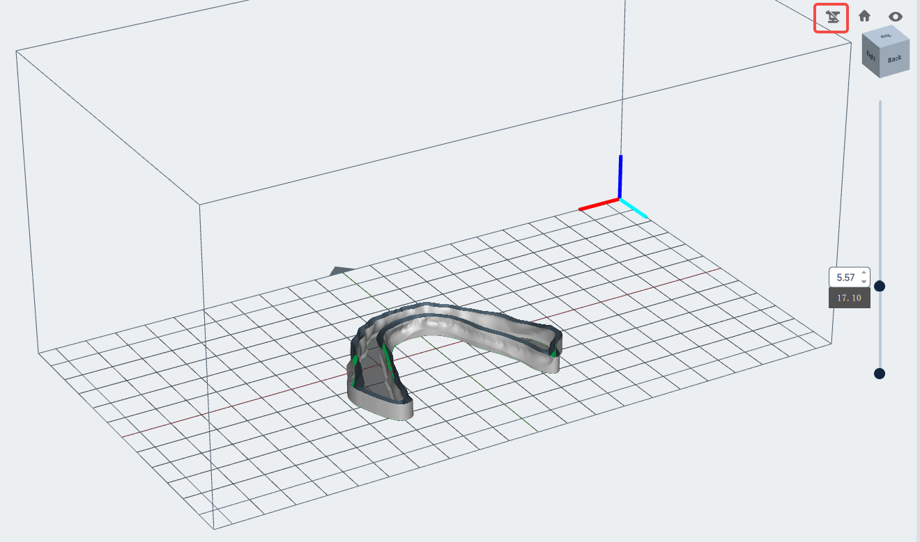
- Platform Icon: One‑click show/hide the platform.
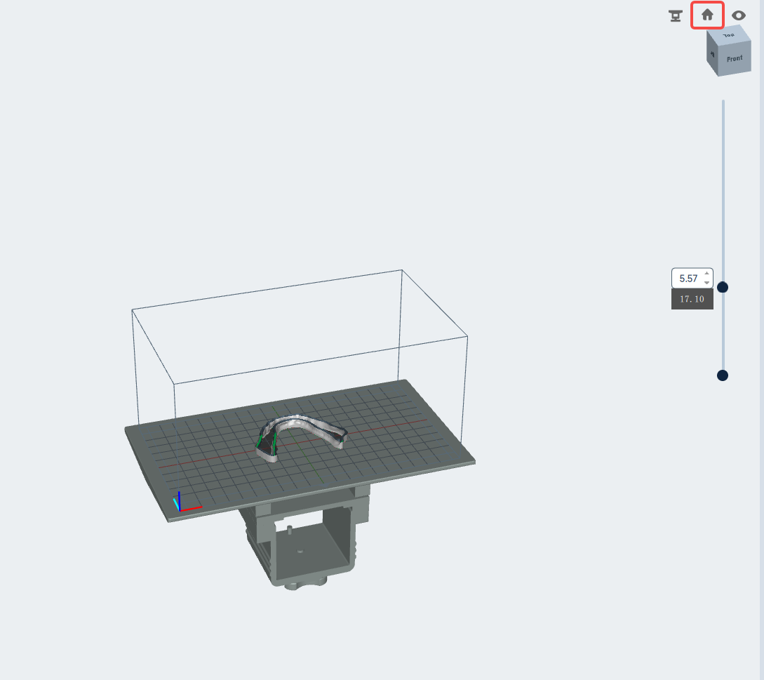
- House Icon: One‑click reset to return to the initial preview view.
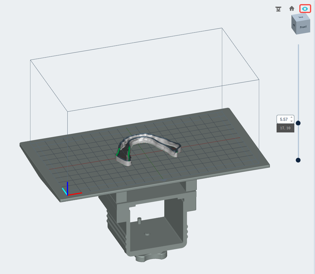
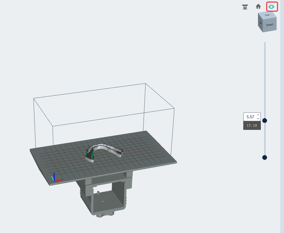
- Eye Icon:Toggle between default far‑view and near‑view modes.
¶ Mouse Operation
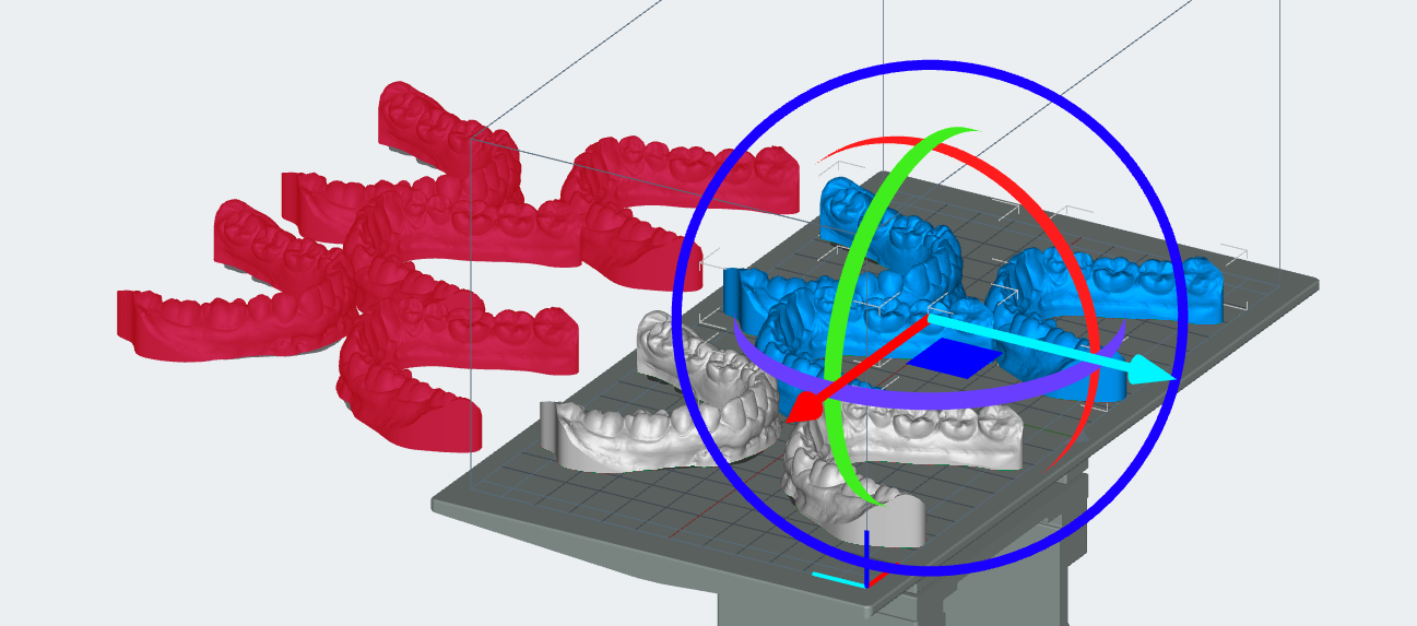
- Left click: Select the model
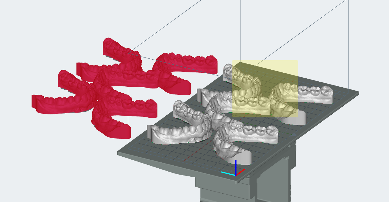
- Long press the left mouse button to select by dragging : Select multiple models in batches
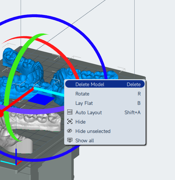
- Right click : Bring up the context menu
- Right‑click on a selected model to bring up the context menu, allowing quick actions such as Delete, Rotate, Snap to Bottom, Layout, Hide, Show, etc.
- Hide: Hides the selected model; once hidden, the model cannot be edited or sliced
- Show All: Unhide all models
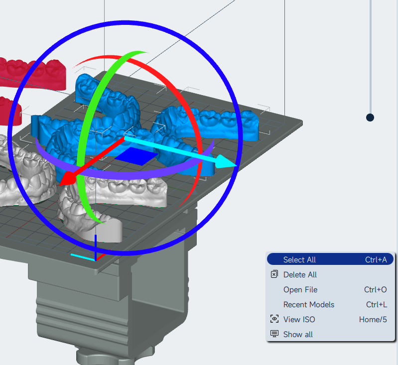
- Right-click the mouse in the area without a model to bring up the right-click menu, where you can perform operations such as select all, delete all, open file, historical models, isometric view, and show all
- Right‑click on a selected model to bring up the context menu, allowing quick actions such as Delete, Rotate, Snap to Bottom, Layout, Hide, Show, etc.
- Right click and hold to drag : Rotate the viewport around the model center.
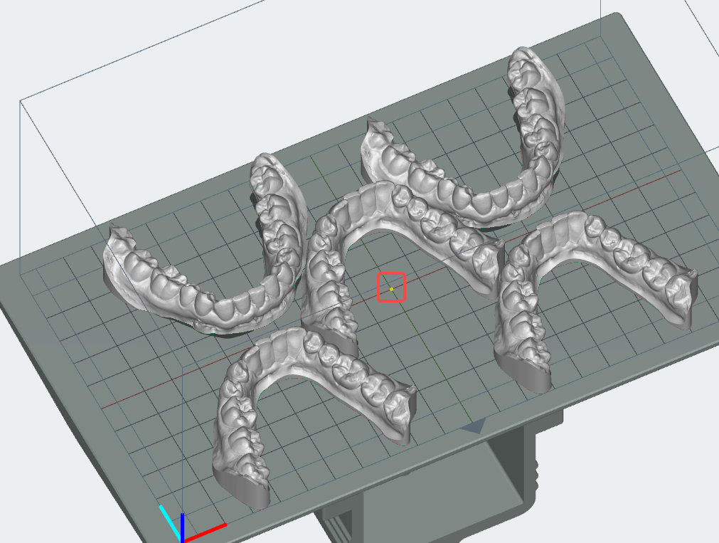
- Long press and drag the middle mouse button : Pan the canvas
¶ 1.3 Left Menu Bar
The left toolbar provides the core functions for model editing and processing.
¶ Open
Import a local STL model file
¶ One-click typesetting
The software automatically adjusts model layout and adds support, requiring no manual adjustment. You can freely choose whether to automatically perform "Orientation", "Supports", and "Layout" operations.
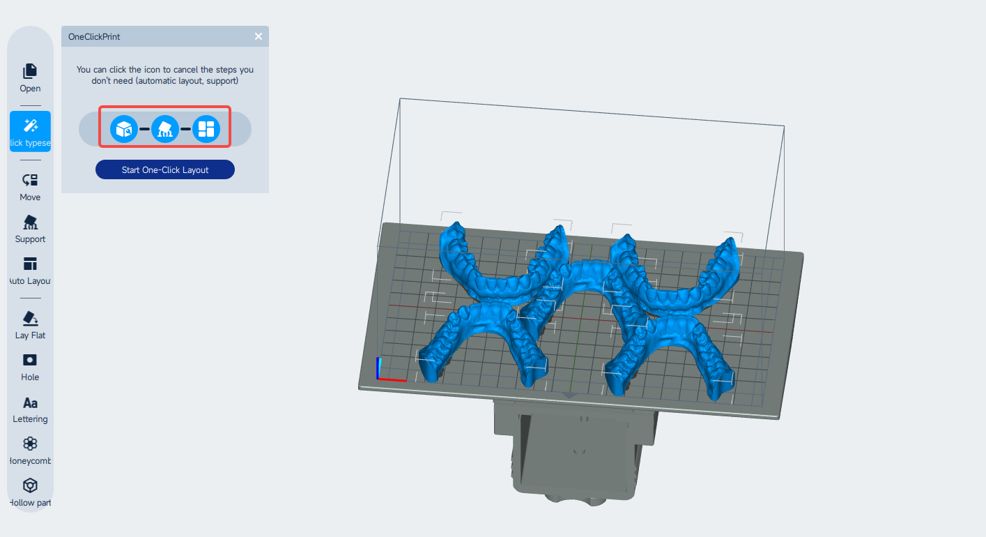
Precautions:
After one‑click layout, it is recommended to manually check. If some models are too close to the platform edge, fine‑tune manually. If supports are unsuitable, regenerate or add them manually.
If the algorithm detects that the model exceeds the platform placement range or part of the model is outside the platform, it is a normal prompt phenomenon, and the model position needs to be manually adjusted.
¶ Orientation
Manually adjust the position and angle of the model
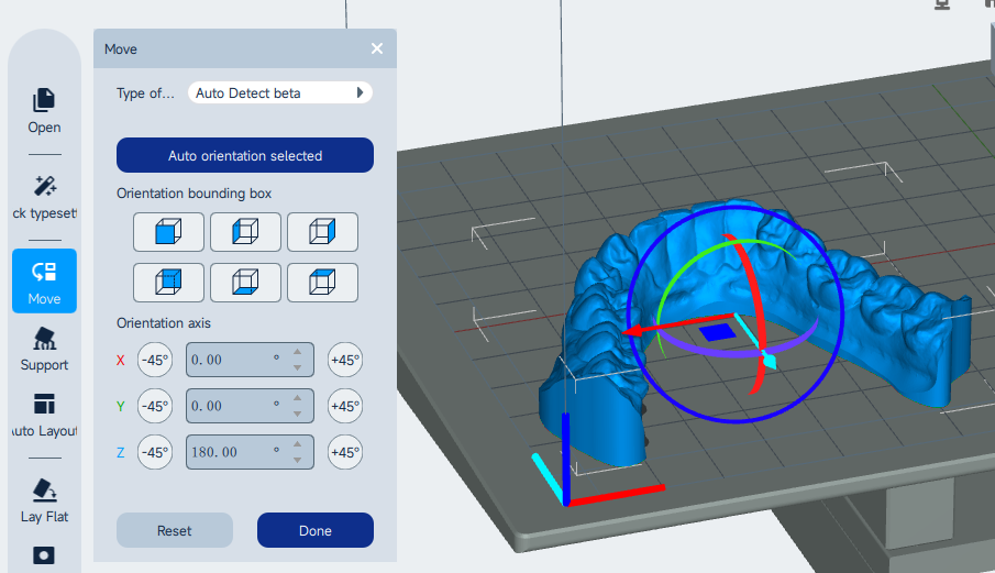
- Auto Orientation Selection : The system automatically calculates the optimal placement angle
- Application Type: Manually select the model type to define rules for auto‑orientation.
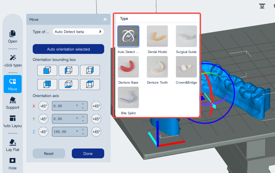
- Orientation Bounding Box : Adjust the model direction via bounding box rotation. Choose to place the model with its Front, Left, Right, Back, Bottom, or Top face against the platform.
- Orientation Axis: After selecting a model, rotate it about the X, Y, or Z axis through its center point. You can input a specific angle or rotate in 45° increments.
- Manual rotation control: Drag the rotation dial with the mouse to manually adjust the angle.
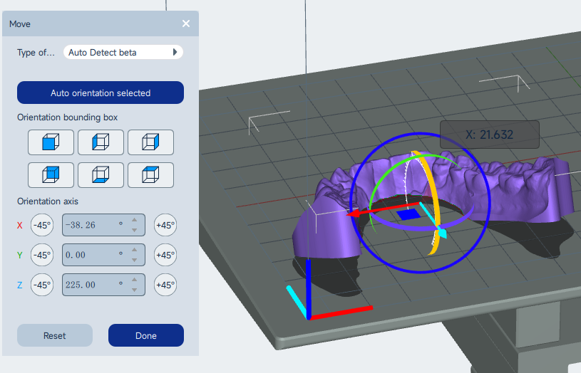
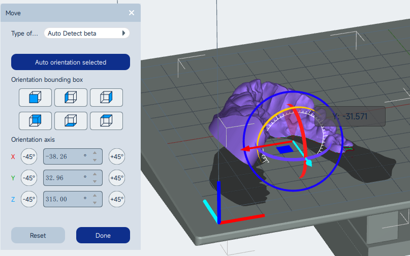
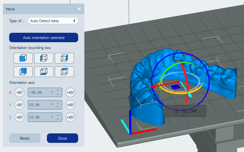
- Dragging the outermost rotation dial rotates the model about the current view axis.
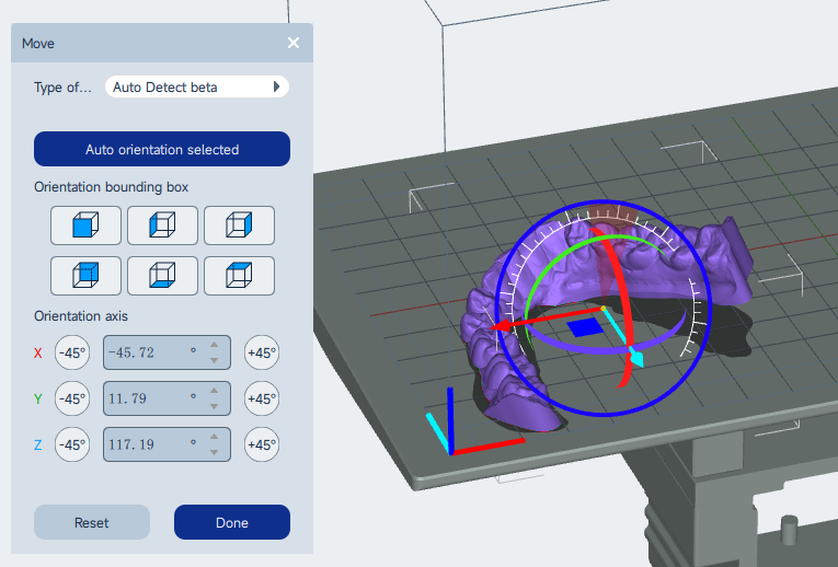
- Manual rotation control: Drag the rotation dial with the mouse to manually adjust the angle.
- Move: After selecting a model, drag it to freely adjust its position.
- Left‑click and drag along the X or Y axis arrow to translate the model only in that axis direction.
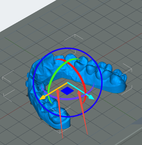
- Left‑click and drag along the X or Y axis arrow to translate the model only in that axis direction.
- Reset: Restore the model to its default position and angle
¶ Support
Add supports to overhanging structures.
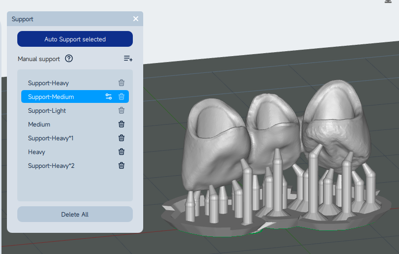
- Automatic Support Selection : Based on the support parameter settings, the system automatically analyzes and adds support structures.
- Support Parameters:
- Heavy support (high strength, suitable for heavy models but difficult to remove)
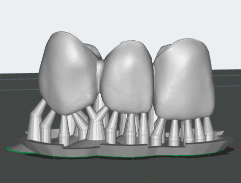
- Medium Support (Standard Setting)
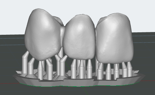
- Light support (suitable for fine structures but with lower strength)
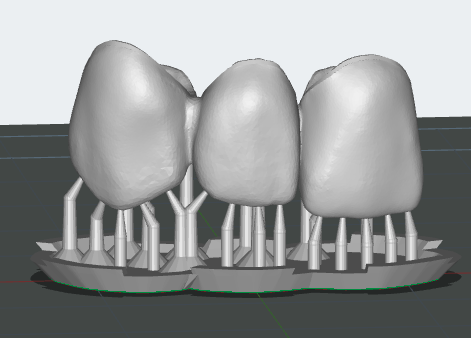
- Heavy support (high strength, suitable for heavy models but difficult to remove)
- Manual Support: Manually add or remove support points
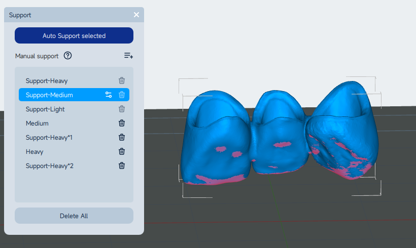
- Operation method: Select and click the model, the model will turn blue, and the support points will turn into golden small spheres
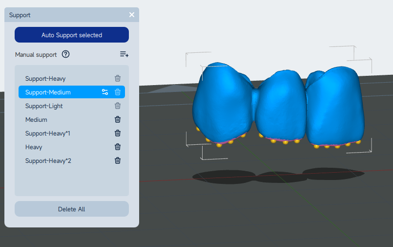
- Manually add support: Left‑click on a position on the model where no support exists; a support point will be generated there.
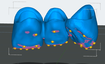
- Manually delete support: Left‑click on an existing support point on the model; that support point will be deleted.
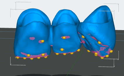
- Hovering the mouse over a spot on the model displays a black contour line.
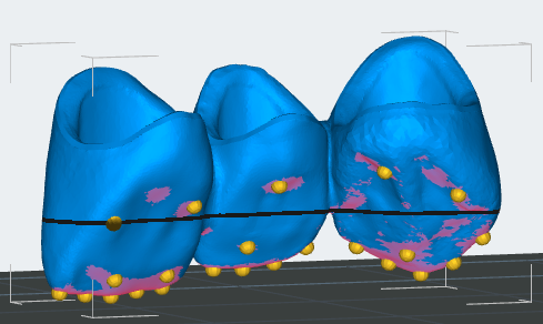
- The position where the contour line shrinks to its minimum must have a support added.
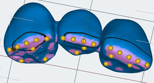
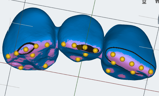
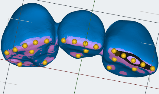
- Pink areas on the model indicate large overhang angles, where supports are recommended.
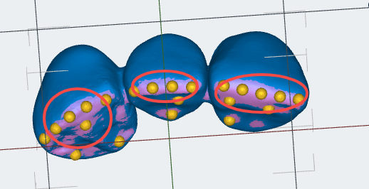
- Click any blank area outside the model to confirm editing.
- Operation method: Select and click the model, the model will turn blue, and the support points will turn into golden small spheres
Precautions: Supports must be added on non‑functional and non‑mating surfaces of the model to avoid affecting usability.
- New Parameter: Copy the selected parameter config
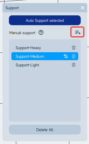
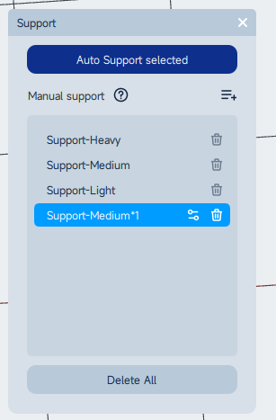
- Double‑click the new parameter name to rename it (default parameters cannot be renamed).
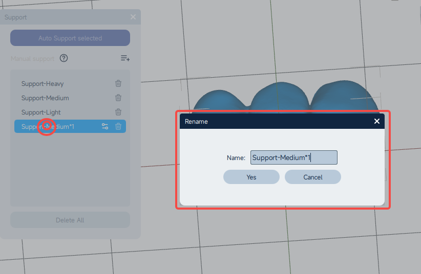
- Double‑click the new parameter name to rename it (default parameters cannot be renamed).
- Support Parameter Adjustment:
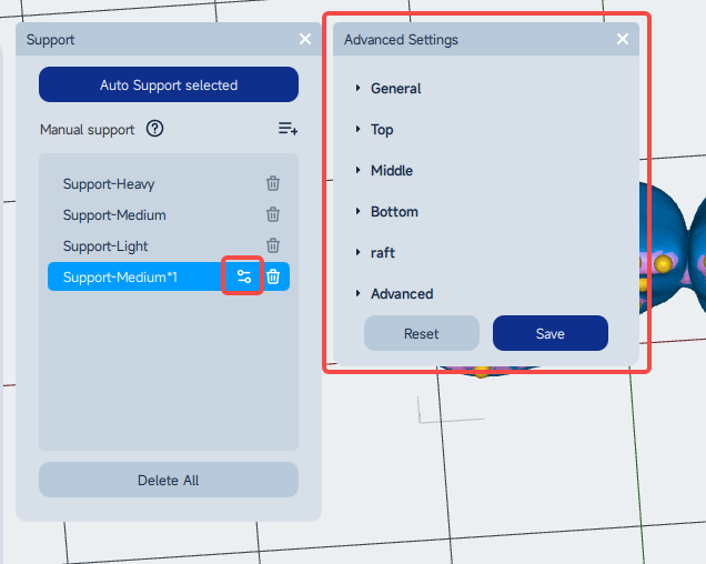
- Height from Platform: The distance from the model’s bottom to the platform. Raising the model leaves space for support.
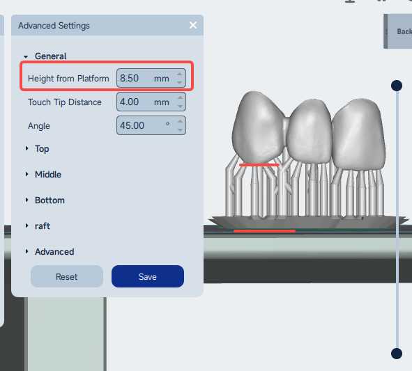
- Touch Tip Distance: The distance between support points when supports are automatically generated
- Decreasing the spacing increases the number of auto‑supports, providing stronger support.
- Generally, light supports require a smaller spacing, while heavy supports require a larger spacing.
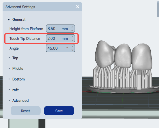
- Angle: The maximum overhang angle at which supports are allowed when auto‑generating.
- Increasing this value typically generates support points over a larger area.
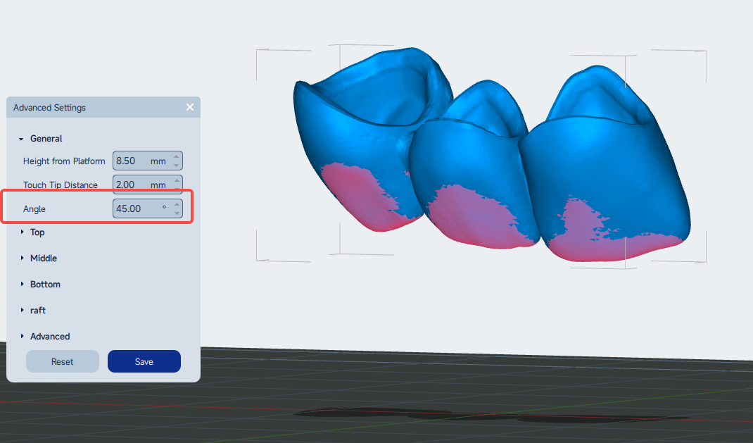
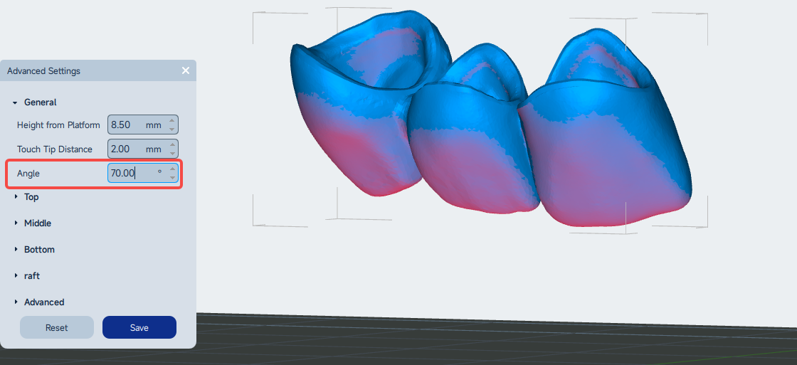
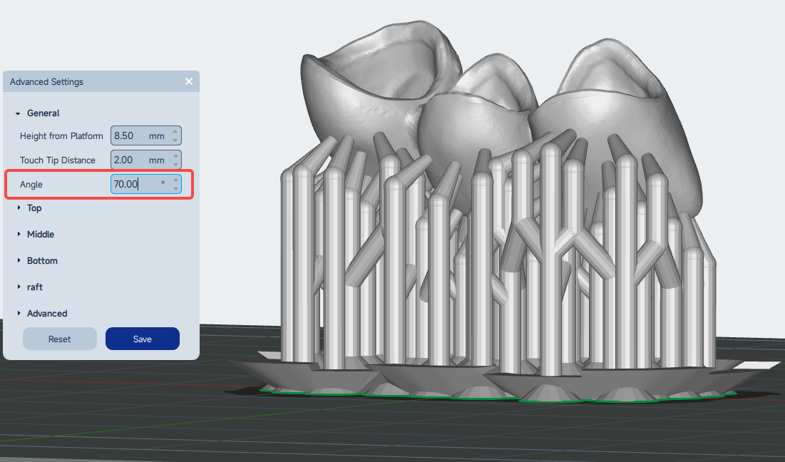
- Increasing this value typically generates support points over a larger area.
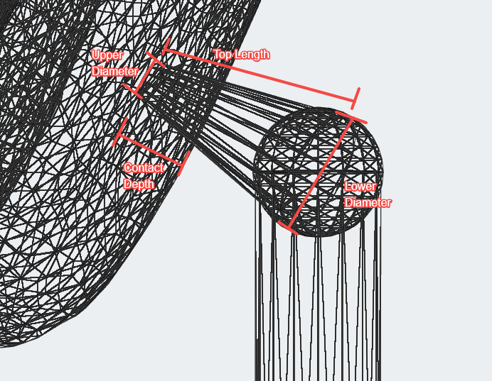
- Top parameters: Parameters for the top part of the support structure.
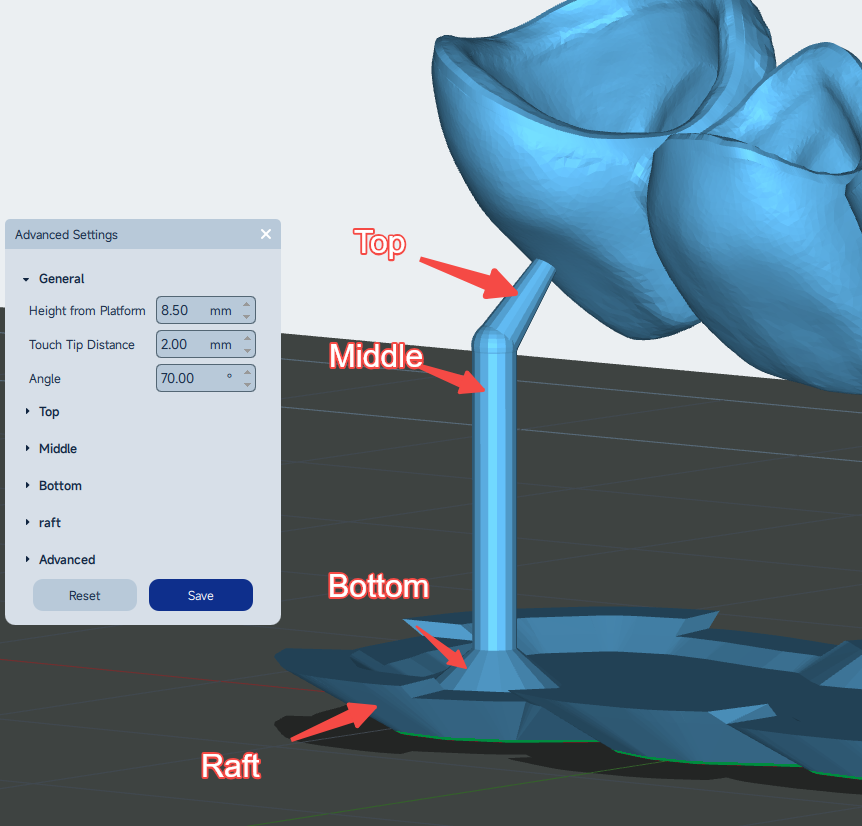
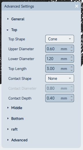
- Top Shape: The shape that supports the top
- Upper Diameter: Diameter of the end that contacts the model.
- Lower Diameter: Diameter of the end connected to the middle support.
- Top Length: Distance from the upper end to the lower end of the top part.
- Contact Depth: Depth that the upper end penetrates into the model.
- Height from Platform: The distance from the model’s bottom to the platform. Raising the model leaves space for support.
- Contact shape: Optional Sphere or None.
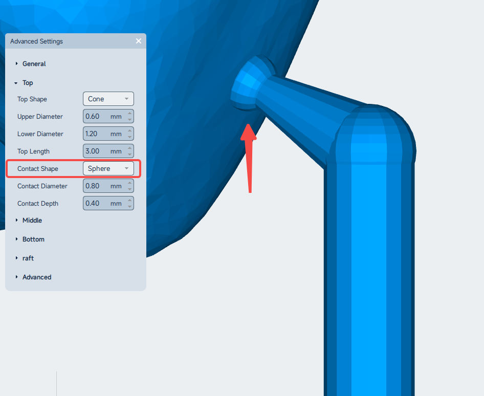
- Contact Diameter: If Contact Shape is set to Sphere, this is the diameter of that sphere.
- Spheres usually require post‑processing sanding, but the advantage is that they do not leave pits on the model when supports are removed.
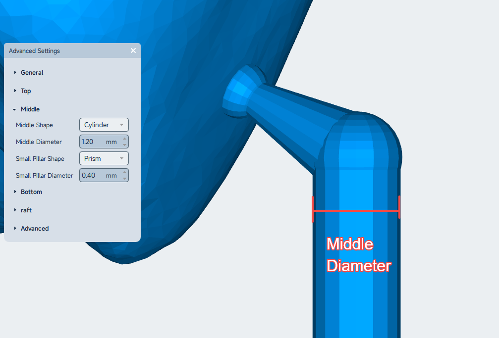
- Middle Shape: The shape of the support middle section.
- Middle Diameter: Diameter of the middle shape.
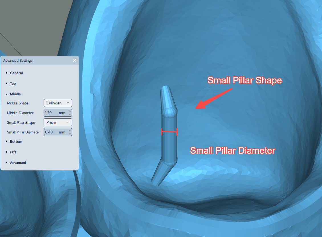
- Small Pillar Shape: Shape of thin supports spanning from one face of the model to another.
- Small Pillar Diameter: Main diameter of the small pillar.
- Bottom Shape: Shape of the support base.
- If Bottom Shape is None, the parameters below are irrelevant.
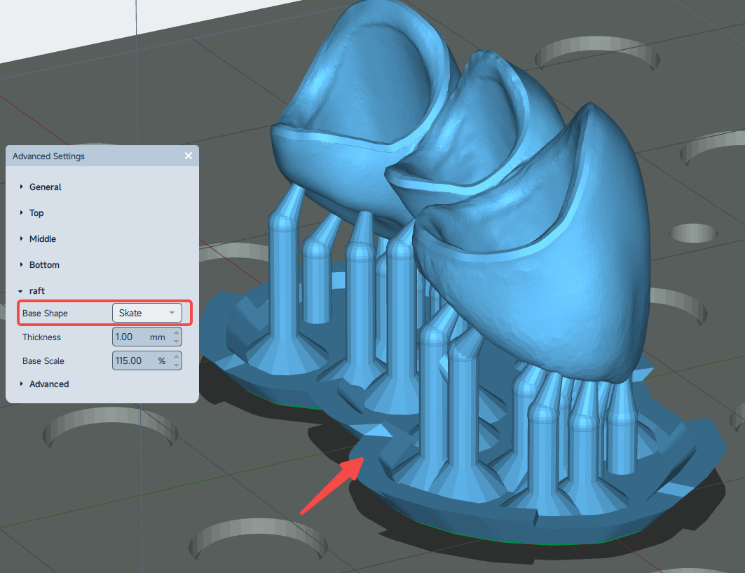
- If Bottom Shape is Cube, you must set Base Shape to None for it to take effect.
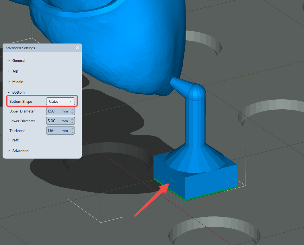
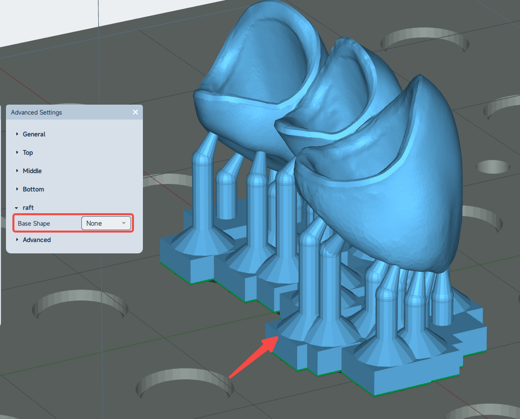
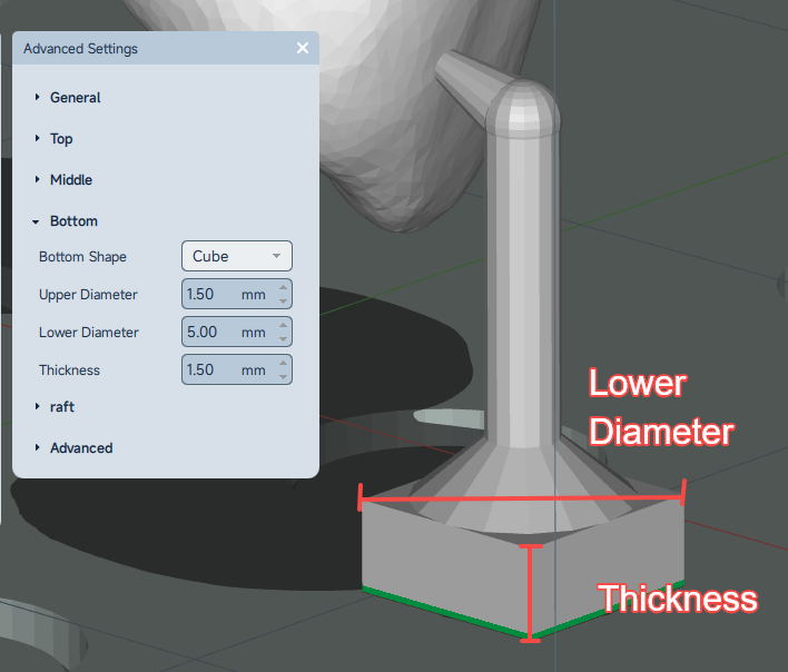
- After Bottom Shape takes effect, you can adjust Lower Diameter and Thickness.
- Lower Diameter:Diagonal length of the cube’s bottom face.
- Thickness: Height of the cube
- Bottom Shape: Option to set the base valve as a skate‑shaped structure.
- Thickness: Thickness of the skate bottom shape.
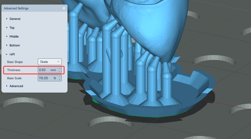
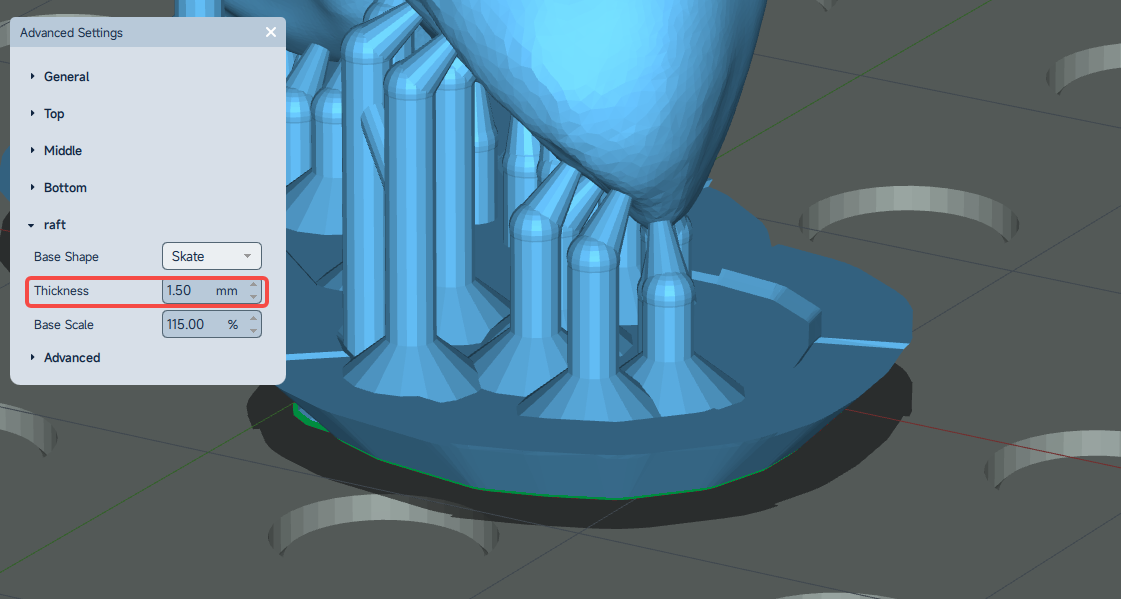
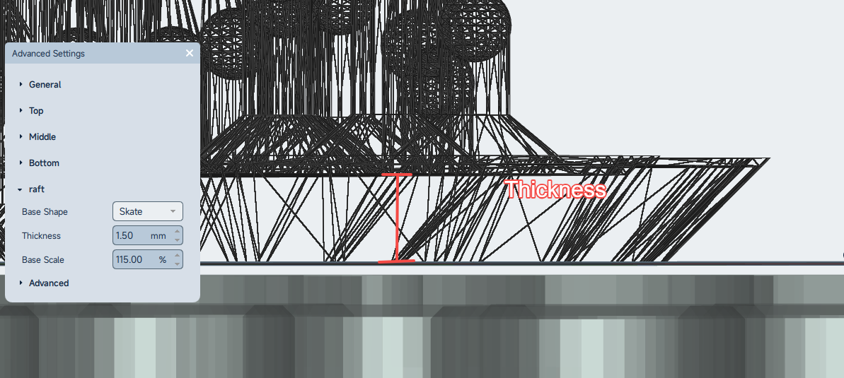
- Base Scale: Ratio of the base valve area to the model’s projected area.
- Increasing the area ratio enlarges the base valve area, helping the model adhere better to the build platform.
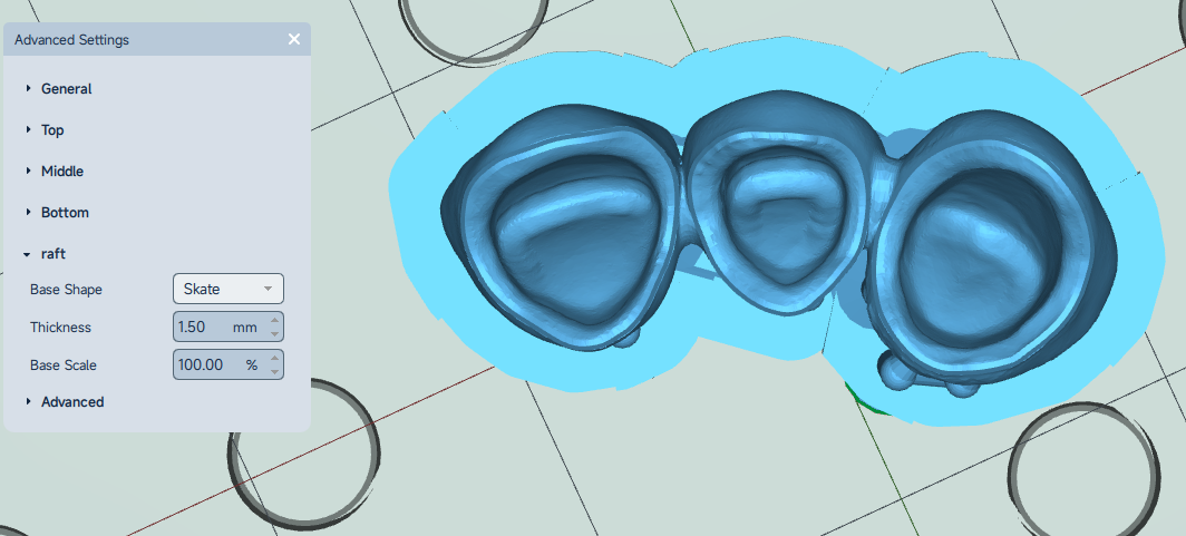
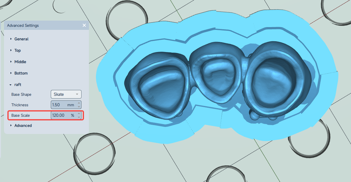
- Increasing the area ratio enlarges the base valve area, helping the model adhere better to the build platform.
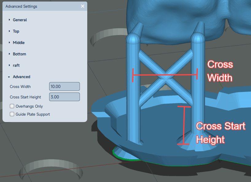
- Cross Width: When the distance between two adjacent middle support structures exceeds this value, a cross‑brace is added between them to stabilize the support structure.
- Crossing Start Height: The crossing structure begins to be generated only after the support exceeds a certain height
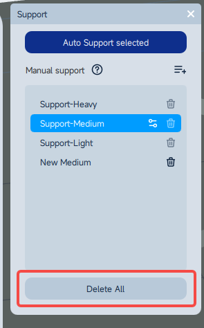
- Delete All: One‑click removal of all supports.
¶ Auto Layout
Batch processes the arrangement and layout of multiple models.
- Margin to Side: The width of the area around the build region where no models are placed during auto‑layout.
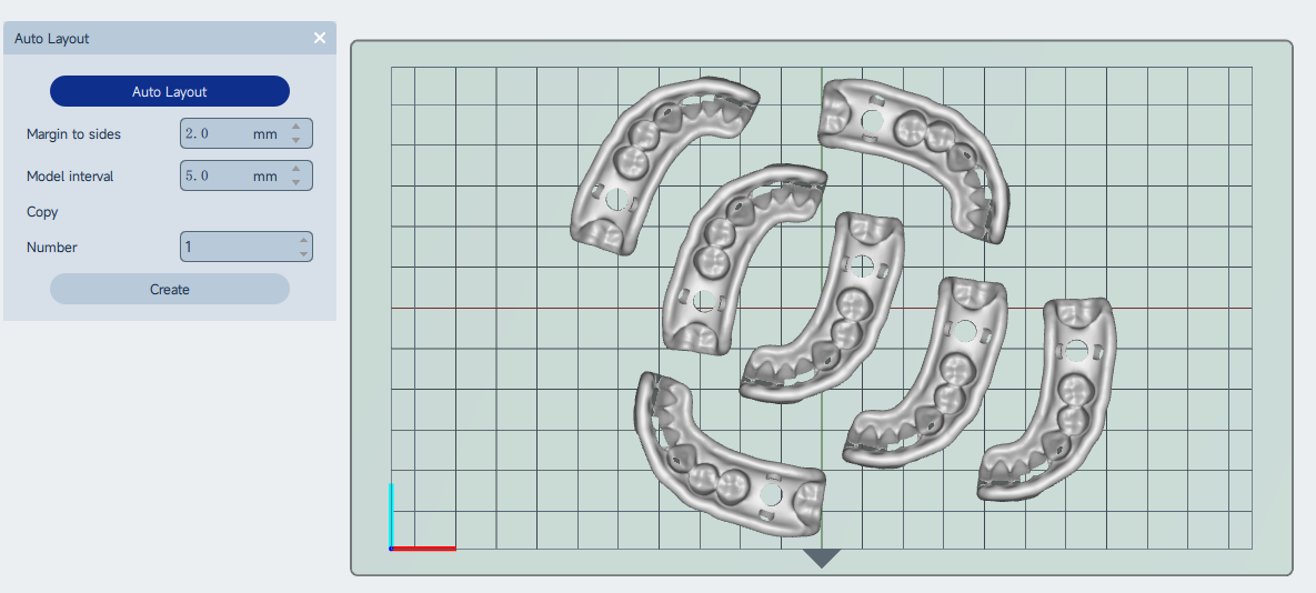
- Model Interval: Set the minimum distance between adjacent models.
- Copy: Duplicate the selected model
- Quantity: Enter the number of copies needed.
- Create: Create the duplicated models according to the entered quantity.
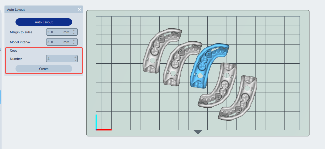
Special Reminder: If any model is outside the platform after layout, it means that under the current layout rules, not that many models can be printed simultaneously. - Layout operations should be performed after adding support.
- After batch duplication, prioritize using the "Layout" function to optimize positions.
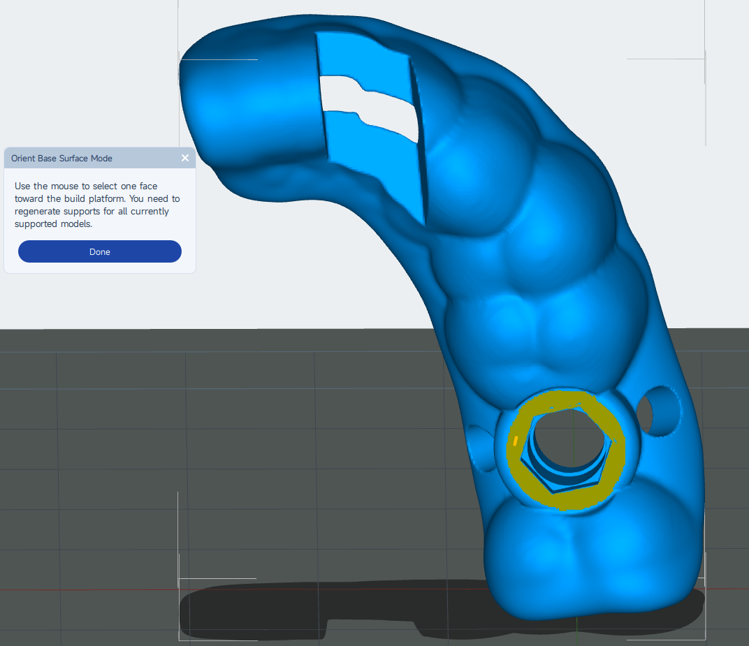
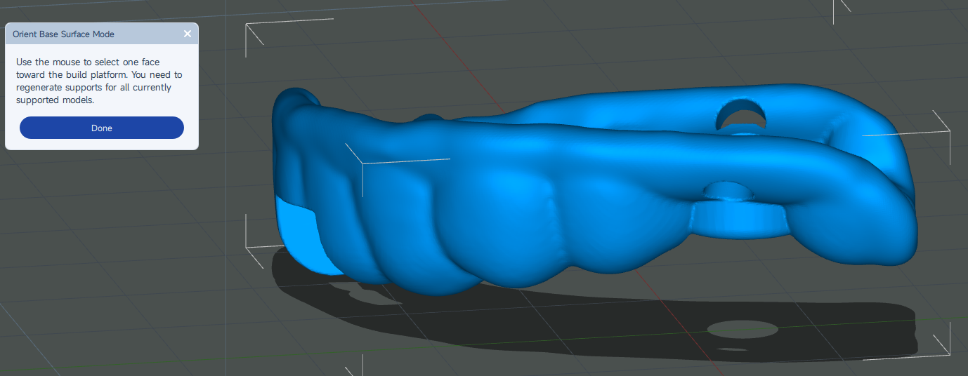
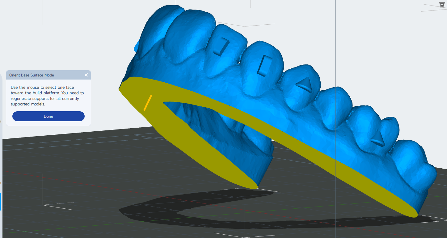
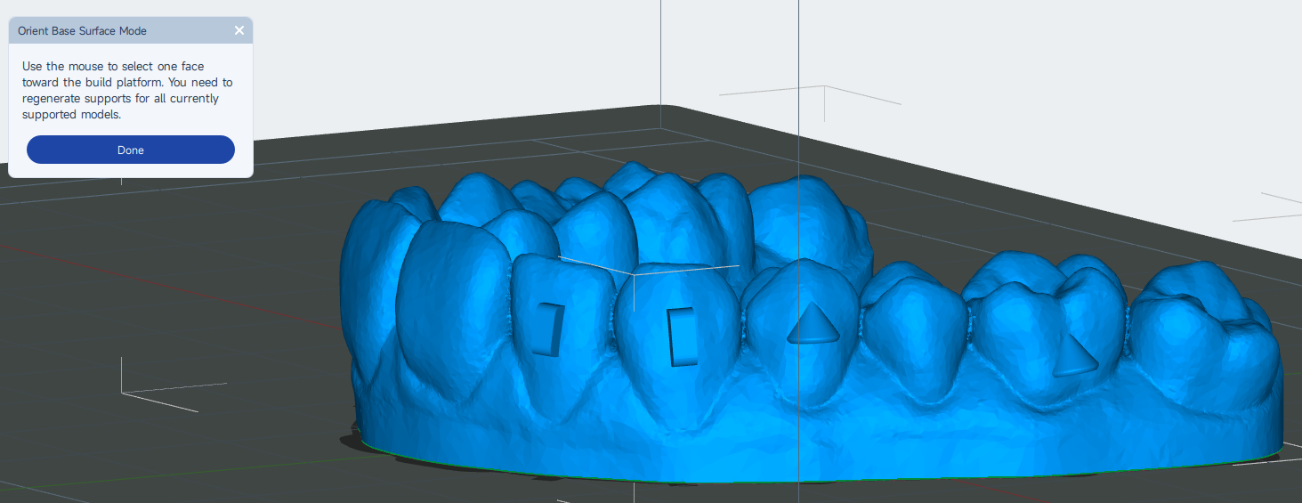
¶ Lay flat
Select a face and place it flush against the build platform or parallel to the platform surface.
¶ Hole
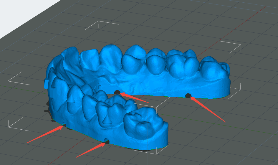
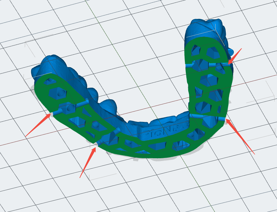
Create holes on the model surface, primarily for hollow models, to eliminate internal vacuum negative pressure, facilitate resin drainage, and prevent print detachment or layer separation.
- Shape: The shape of the created hole, optional circular, square, or triangular
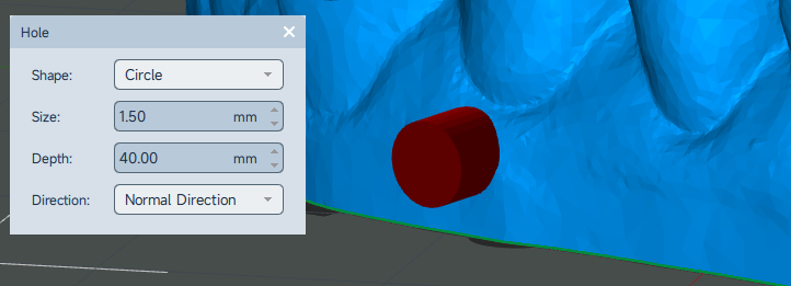
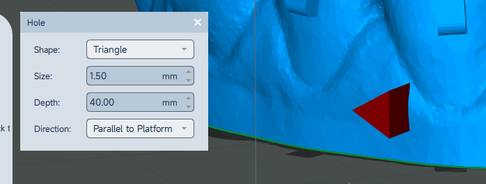
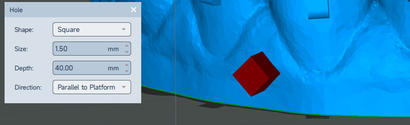
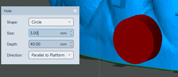
- Size: The diameter/size of the hole.
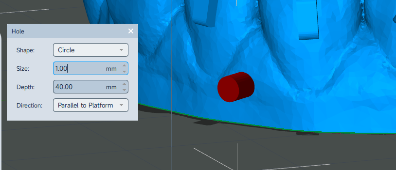
- Depth:Depth of the hole
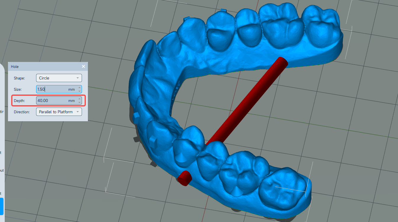
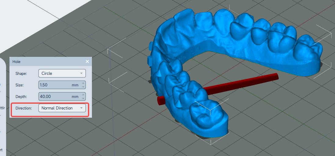
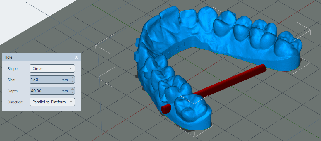
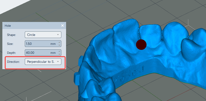
- Direction:
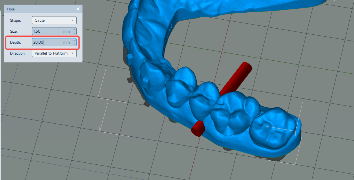
- Parallel to Platform: The axis of the generated hole is always parallel to the platform.
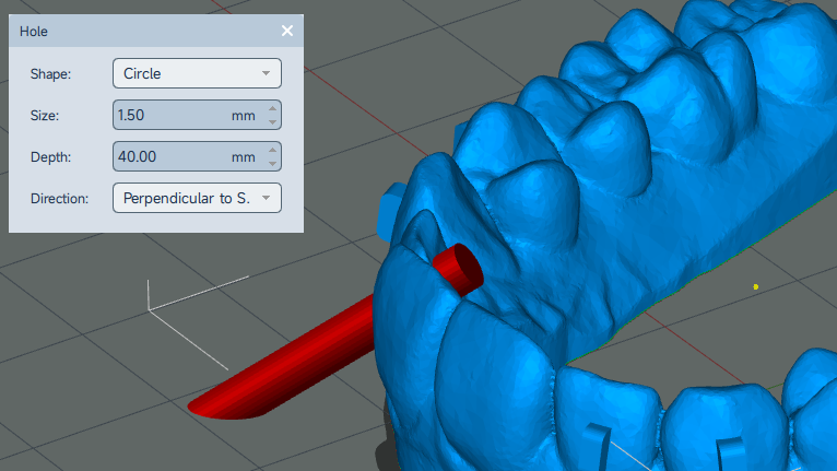
- Perpendicular to Screen: Drill holes perpendicular to the computer display screen
- Hole Position: Select a non‑functional area on the model bottom. Hover the mouse over a face; the software will indicate the hole direction. Click to generate the hole.
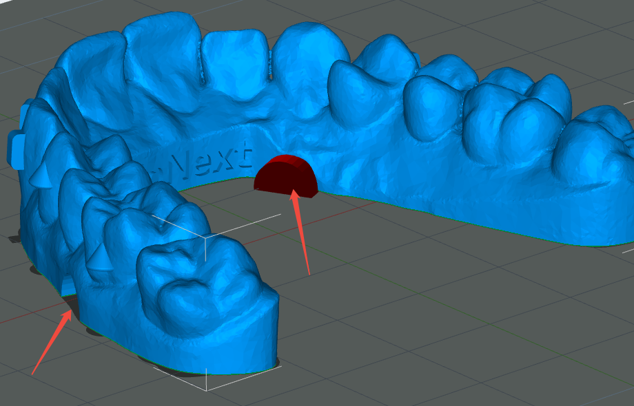
- Parallel to Platform: The axis of the generated hole is always parallel to the platform.
Precautions: Hollow models must have holes, and holes must not be blocked. For large models, evenly drill 4‑6 holes to ensure complete negative pressure elimination.
¶ Lettering
Add raised or incised text on the model surface.
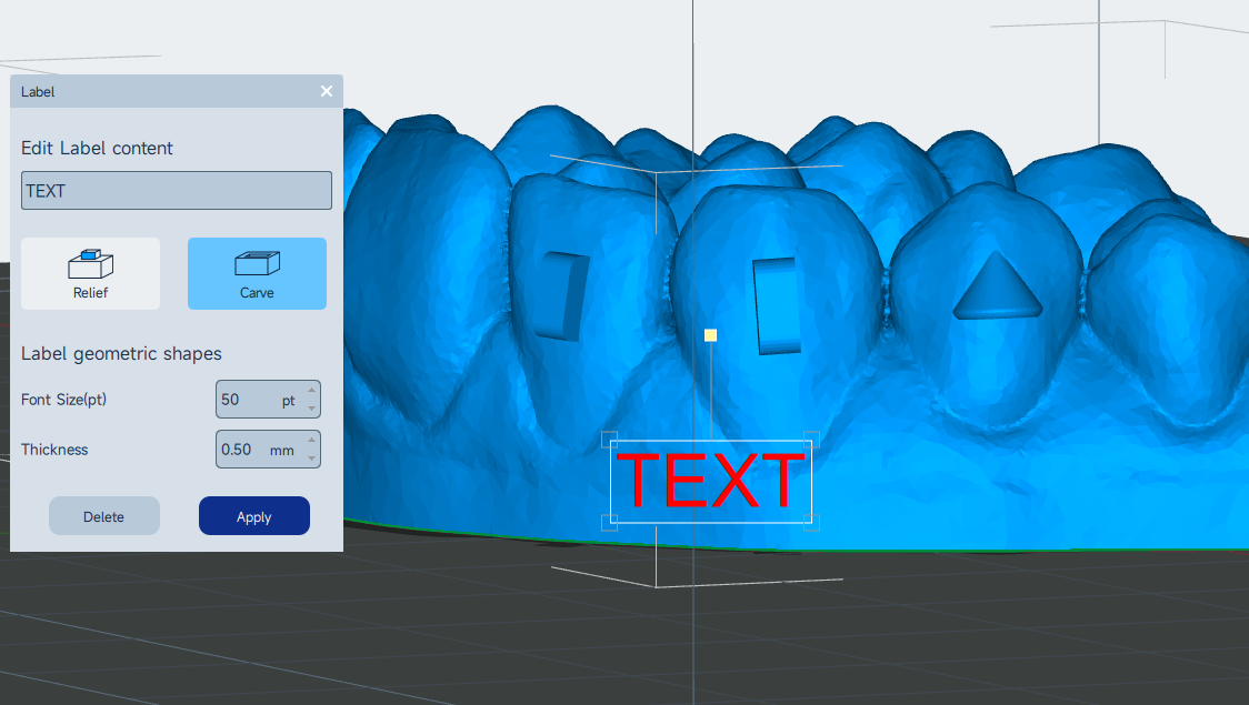
- Edit label content : Enter the text content to be engraved
- Relief: Text raised above the model surface.
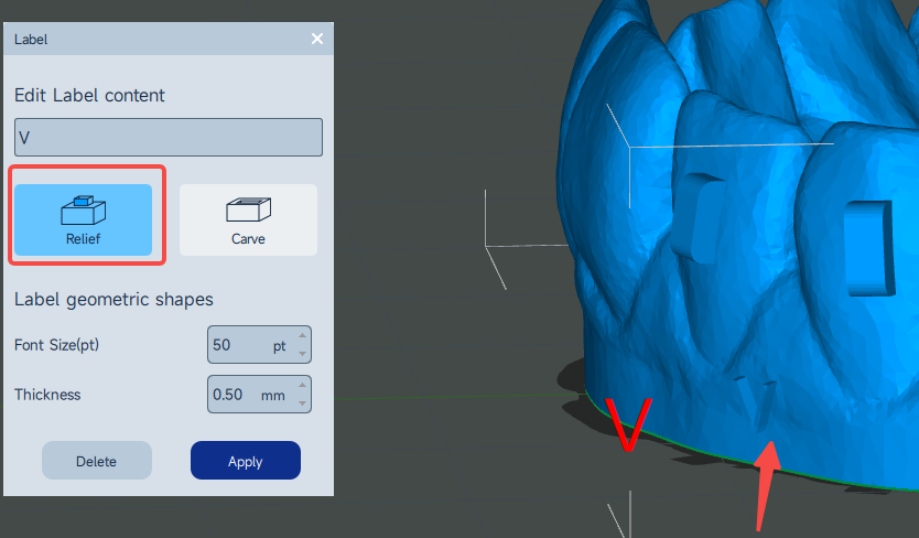
- Crave: Text is recessed into the model surface
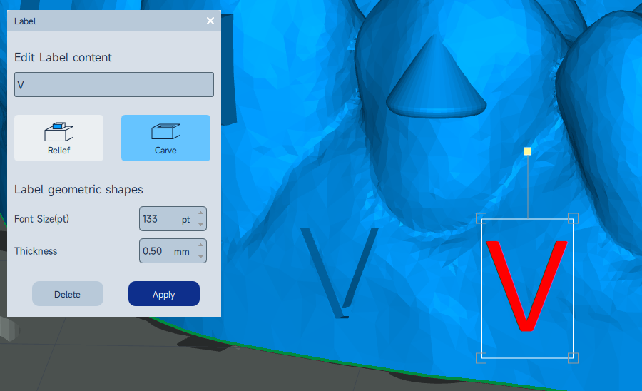
- Font Size(pt): Sets the size of the text
- Thickness: Set the depth of raised or recessed text.
- Operation Method: Drag the text with the mouse, pan the canvas, or rotate the view to adjust the engraving position.
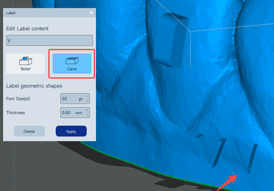
- Operation Method: Drag the text with the mouse, pan the canvas, or rotate the view to adjust the engraving position.
¶ Honeycomb Structure
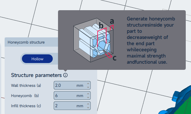
Create honeycomb hollow filling, including Honeycomb Shell and Honeycomb Backfill modes. The core purpose is to replace traditional solid structures, forming a honeycomb pattern inside the model to save resin while maintaining basic structural strength.
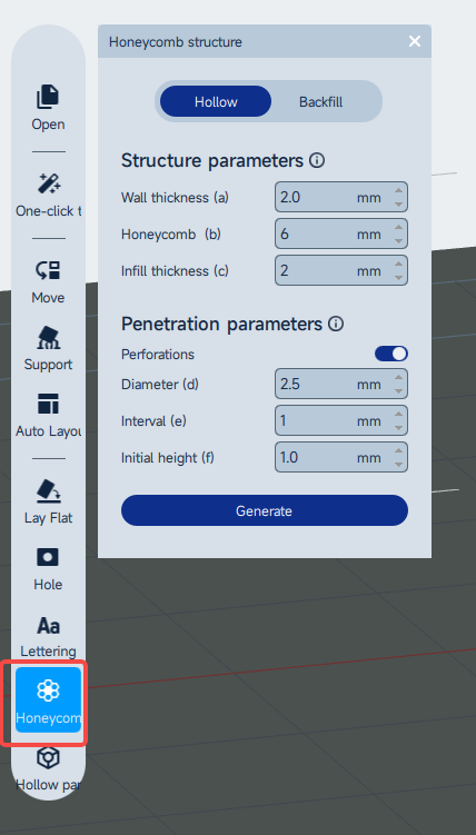
- Hollow: Hollow out a solid model and backfill with honeycomb structure.
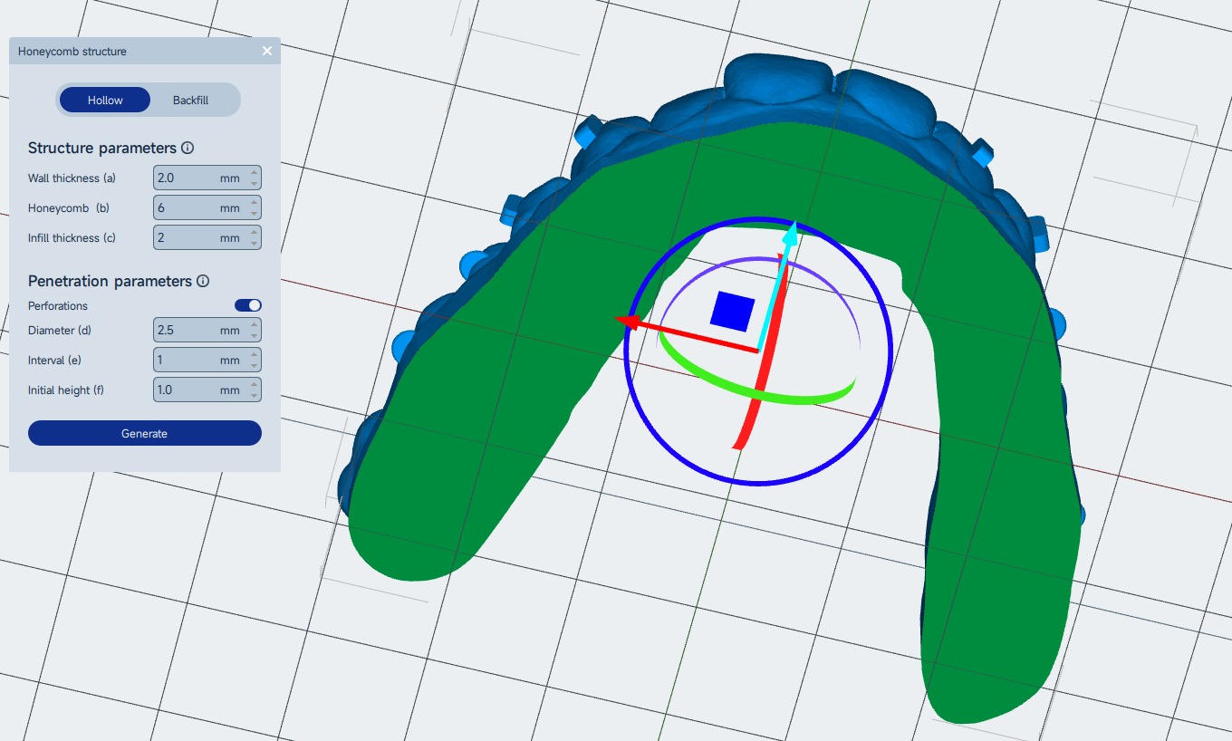
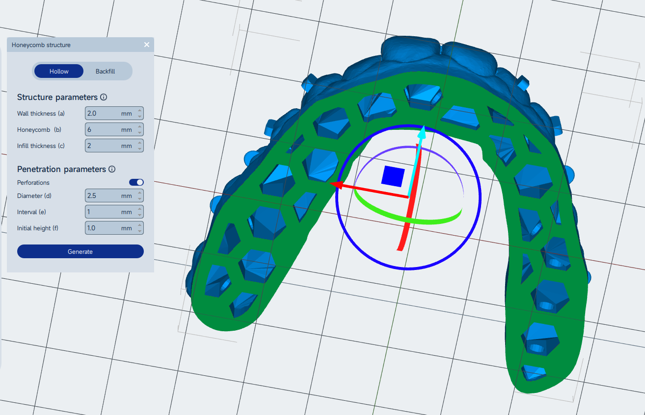
- Wall Thickness: The thickness of the shell remaining after shelling
- Honeycomb : The longest diagonal length of a honeycomb cell, controlling cell size.
- Infill Thickness: The thickness of the honeycomb walls.
- Pemetration parameters : Add through‑holes on the honeycomb fill walls to drain material that might be trapped in closed areas of the honeycomb structure.
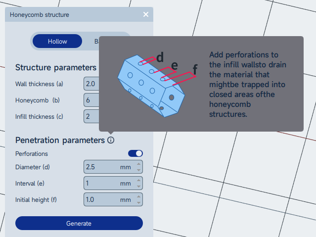
- Pemetration: Enable/disable through‑holes – must be enabled.
- Diameter: Diameter of the through‑holes.
- Interval: Distance between through‑holes.
- Starting Height: At what print height to start adding through‑holes.
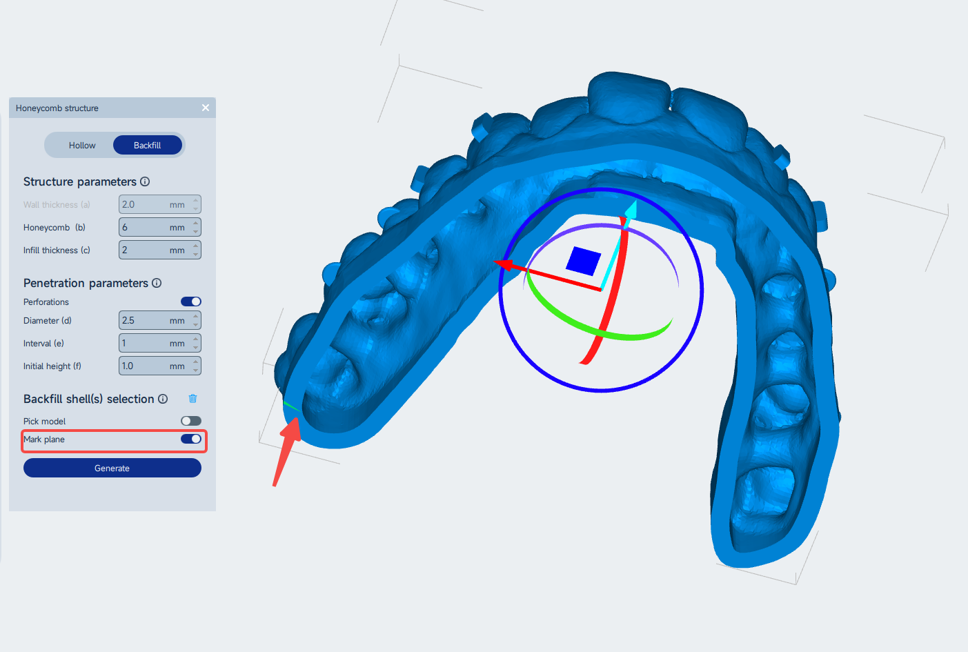
- Backfill: Apply honeycomb backfill to an already shelled model.
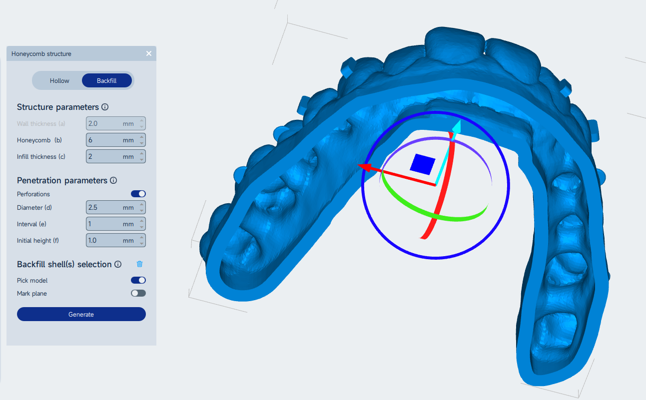
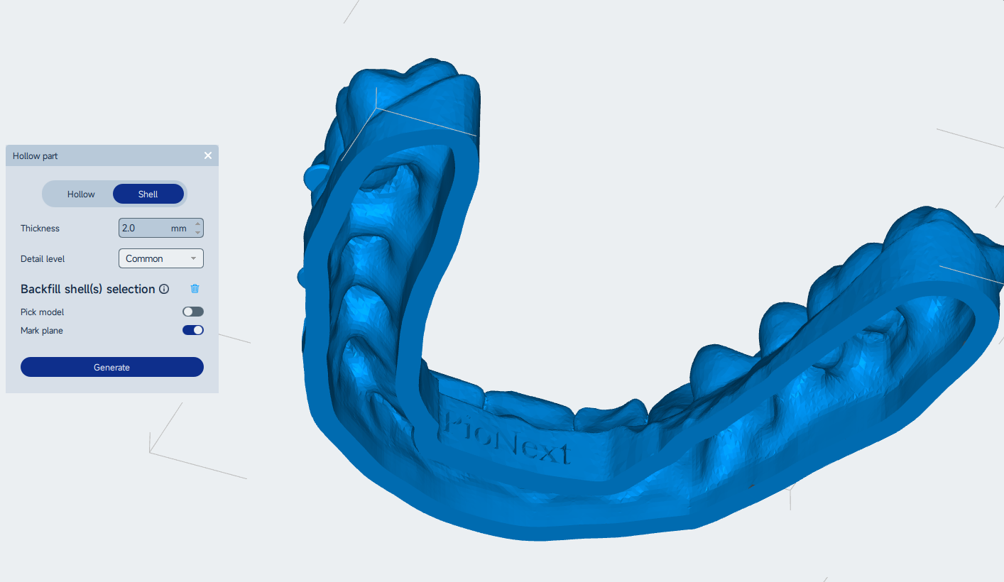
Backfill parameters include an additional backfill shell selection - Pick Model: Choose the model to apply honeycomb backfill.
- Mark Plane: Select the face to backfill, usually the bottom face of the model.
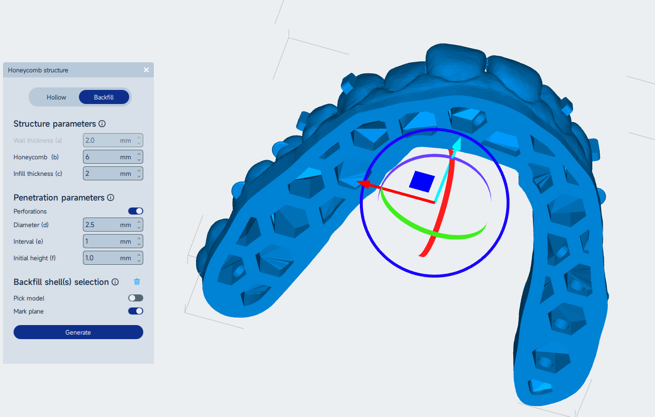
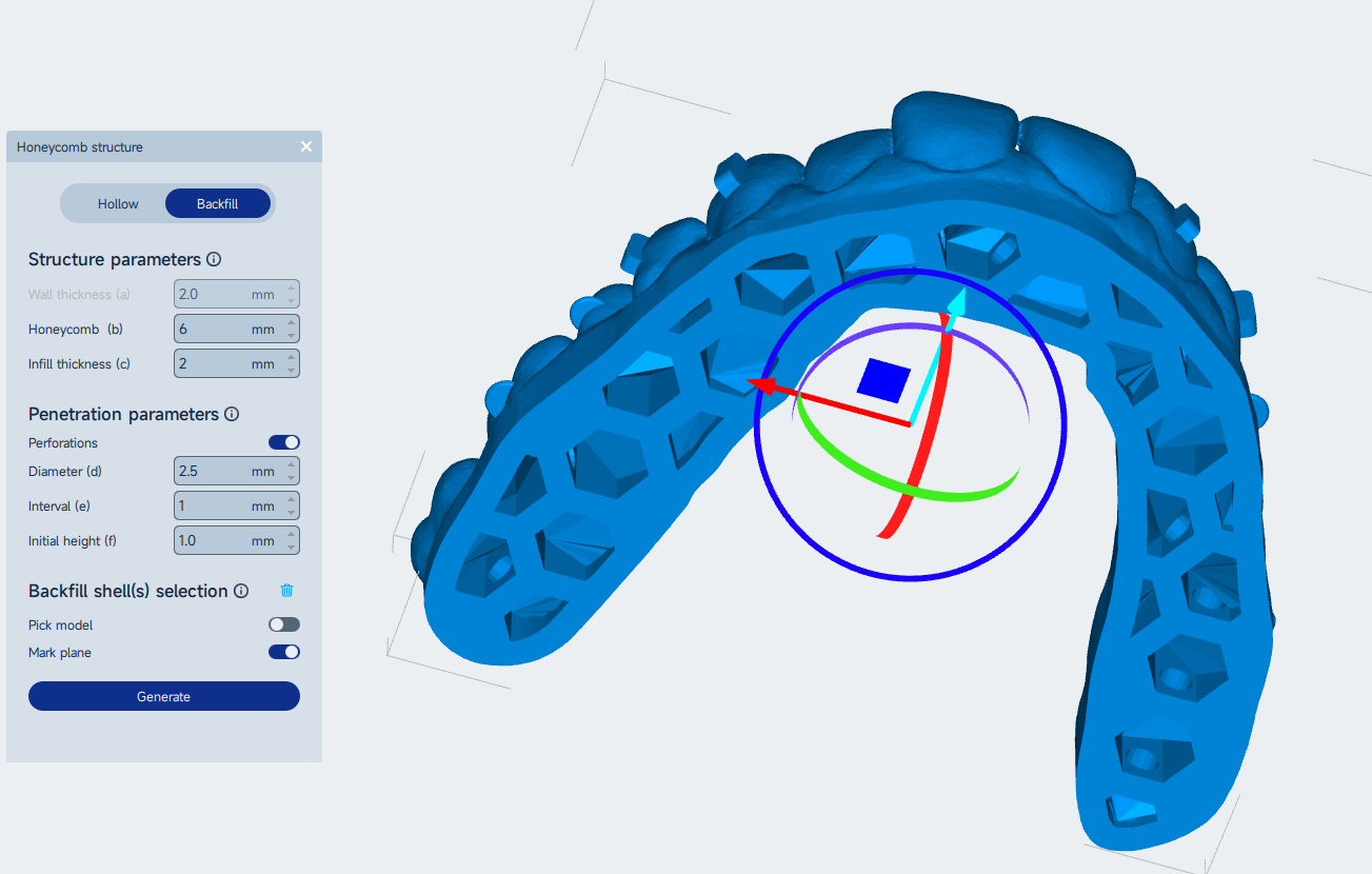
Precautions: Models after honeycomb shelling or backfill must be used together with the "Hole" function; otherwise, sealed hollow cavities will create negative pressure and cause print failure.
¶ Hollow
Hollow out the model interior to save resin and reduce weight, including two modes: Hollow and Shell (without bottom).
- Hollow: Remove the internal material of the model while retaining the bottom surface of the model
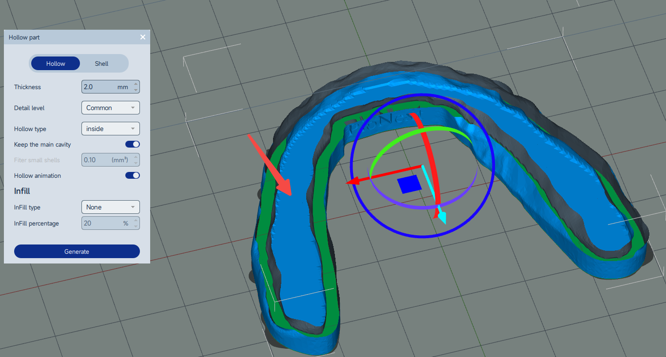
- Wall Thickness: Set the shell thickness retained after hollowing.
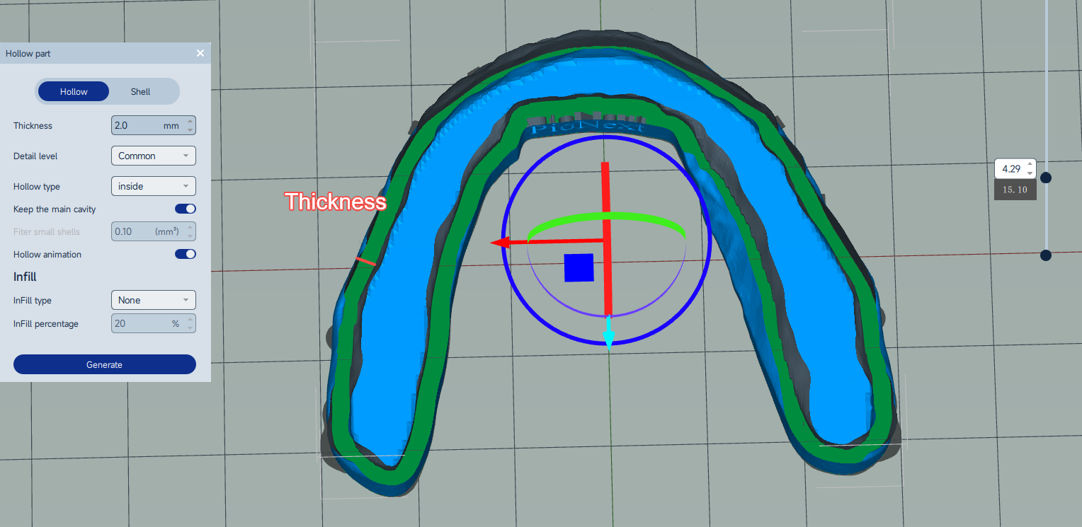
- Detail Level: Fineness of the internal surface after shelling.
- Hollow Type: Select different hollow algorithms.
- Inside: Completely hollow after shelling .
- Self-support: After shelling, generate support structures inside to support the top surface.
- Angle : Maximum overhang angle at which supports are allowed when auto‑generating.
- Increasing this value typically generates support points over a larger area.
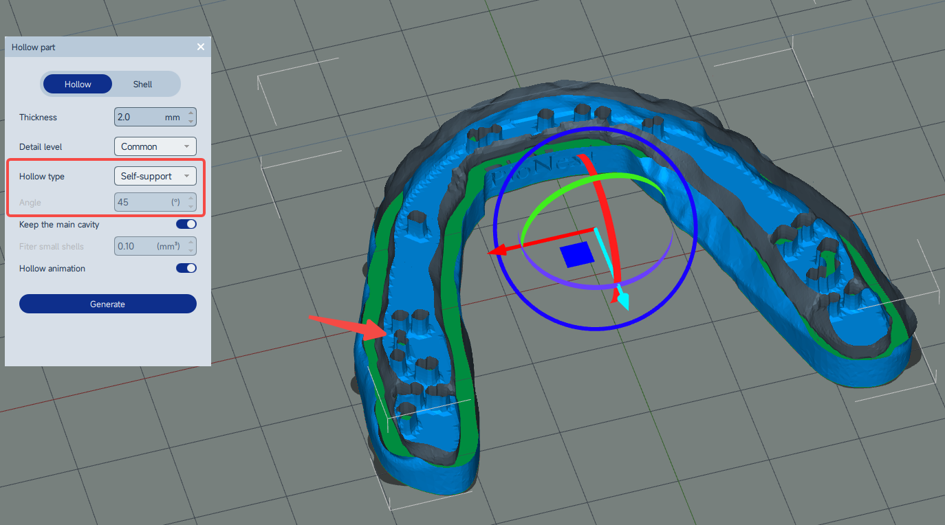
- Increasing this value typically generates support points over a larger area.
- Keep the main cavity: Filter out small internal cavities
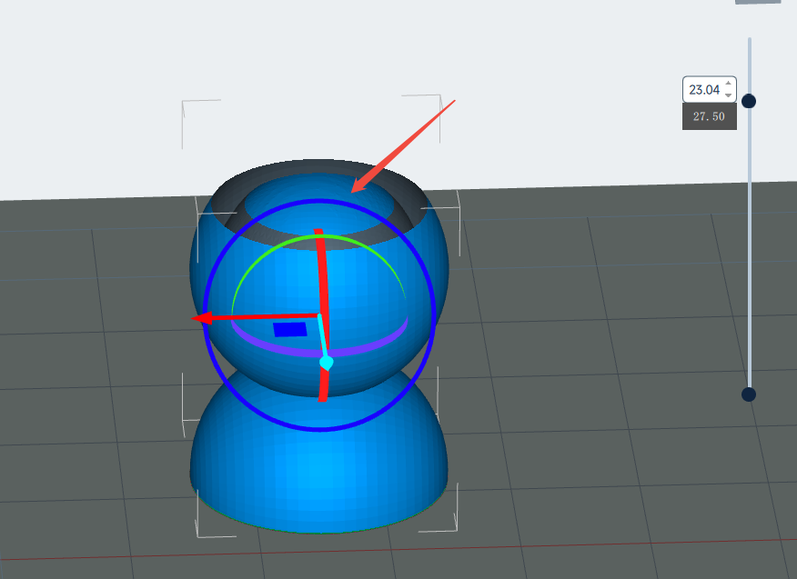
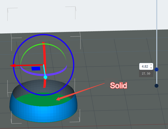
- Filter small shells : Automatically remove shell structures that are too small
- Hollow Animation: When enabled, automatically plays a slice preview animation layer by layer once.
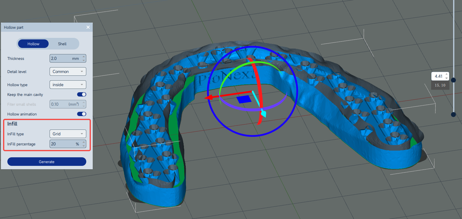
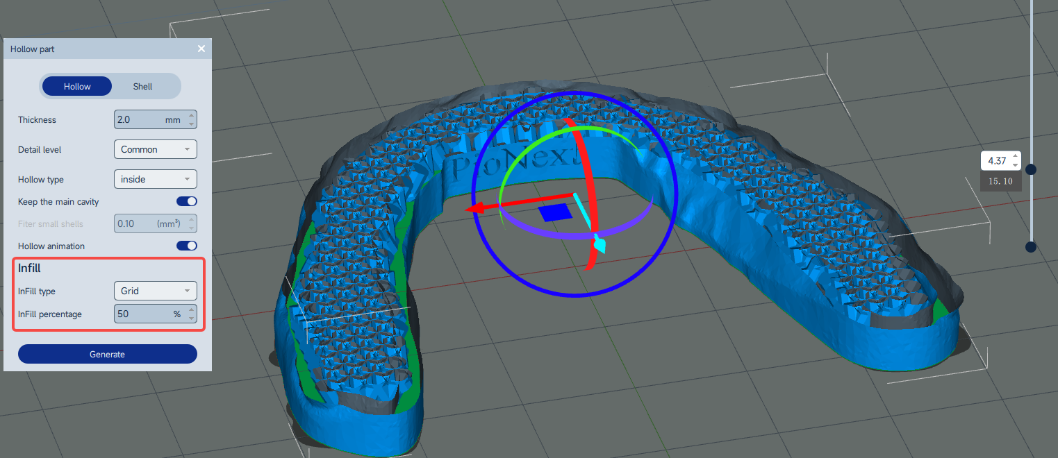
- Infill: Set the infill pattern after hollowing.
- Infill Type: Select the infill pattern style.
- Infill Percentage: Select infill density; higher value means denser infill.
- Shell : Convert a solid model into a shell without a bottom surface
Precautions:
When using hollowing, it is recommended to keep sufficient wall thickness (≥1mm recommended). Too thin a wall may deform or collapse under resin pressure during printing.
Hollowed models must be used with the "Hole Drilling" function; otherwise, sealed hollow cavities will create negative pressure and cause print failure.
¶ 1.4 Right Side Menu
The right area provides functions for printer settings, model list, print preview, and print control.
¶ Printer Settings
- Printer Settings: Select the printer model and resin type
- Select the machine model based on the actual situation
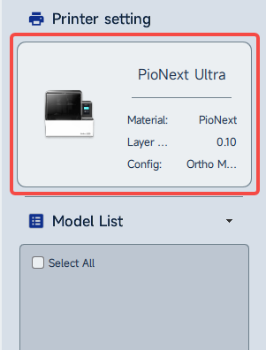
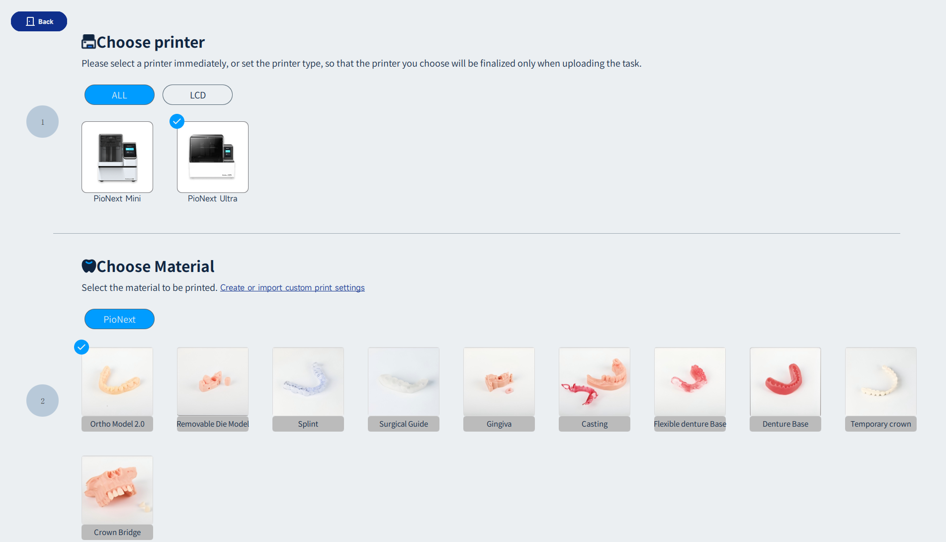
- Select the machine model based on the actual situation
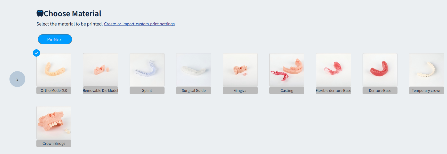
- Select Material:
If official dental resin is used, please directly select the corresponding resin type, which includes the printing parameters for that resin
Create or import custom print settings: Click to edit built‑in parameters or add a new parameter set, which can be used when using other resin materials.
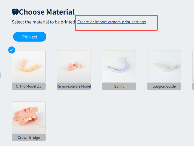
- Import Profile : Create Custom Print Parameter Configuration
- Enter the Resin brand name, and resin type, upload a resin image (optional), modify the parameters, and then click "Finish".
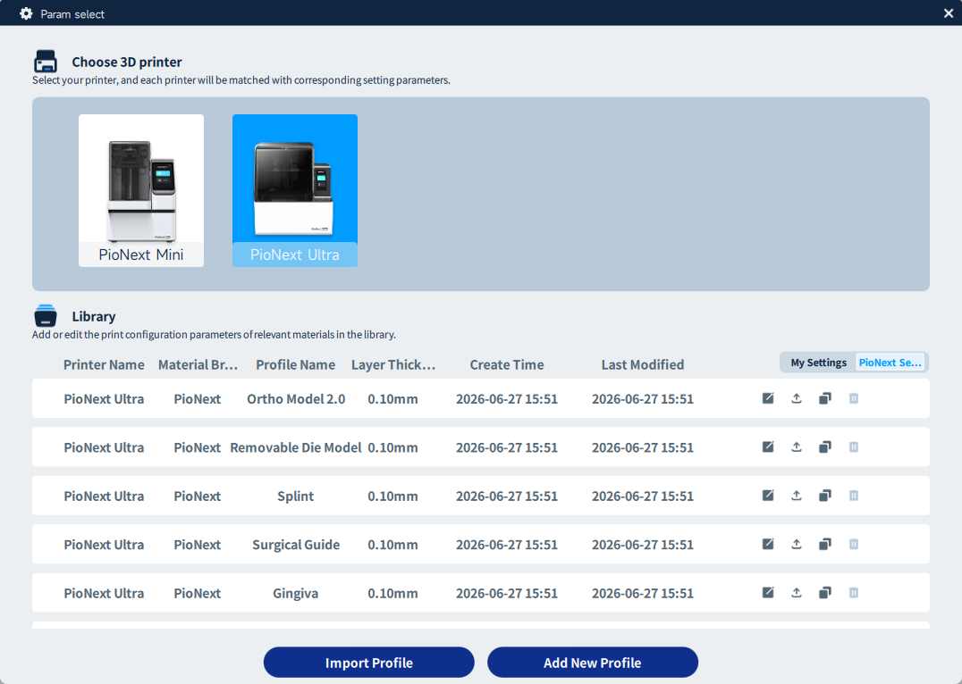
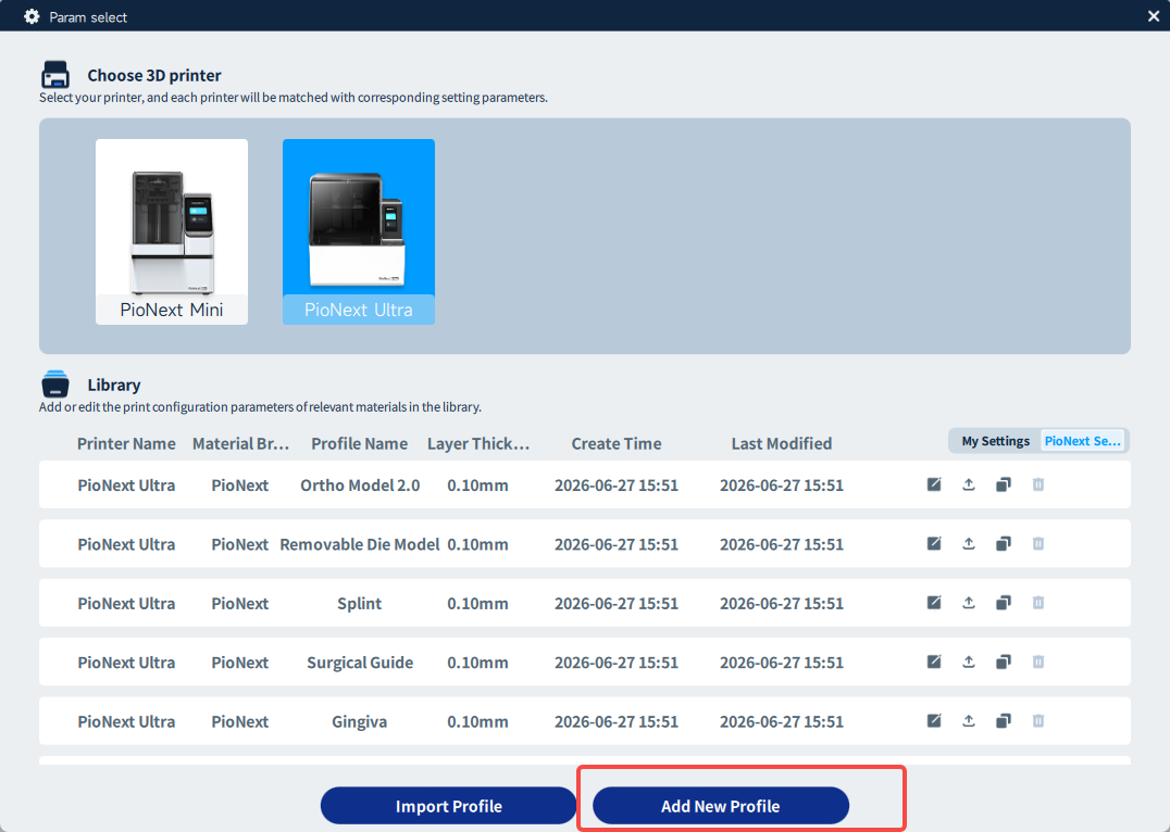
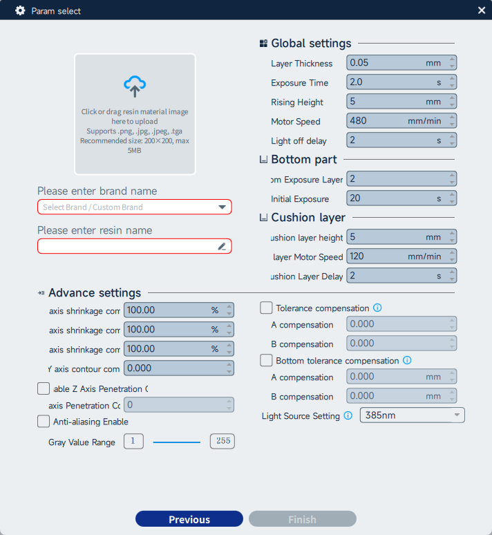
- Enter the Resin brand name, and resin type, upload a resin image (optional), modify the parameters, and then click "Finish".
- Edit Parameter Set: Click the edit icon to adjust it.
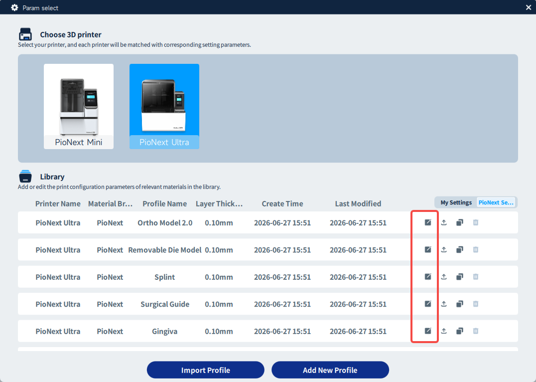
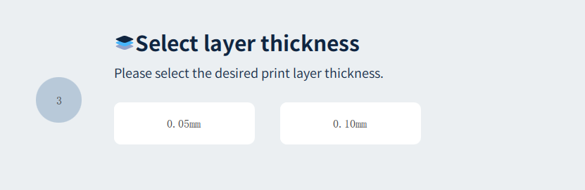
- Select Layer Thickness: Select the printing layer thickness (which affects printing accuracy and speed). The smaller the thickness, the more delicate the model, but the longer the printing time; the larger the thickness, the shorter the printing time, but the rougher the surface. Generally, 0.05mm is recommended, and for those pursuing speed, a layer thickness of 0.1mm can be selected
- Apply: Apply the current parameter settings to the slice
¶ Model List
-
The list displays all models currently loaded in the scene.
-
Click a model to toggle its selection state.
-
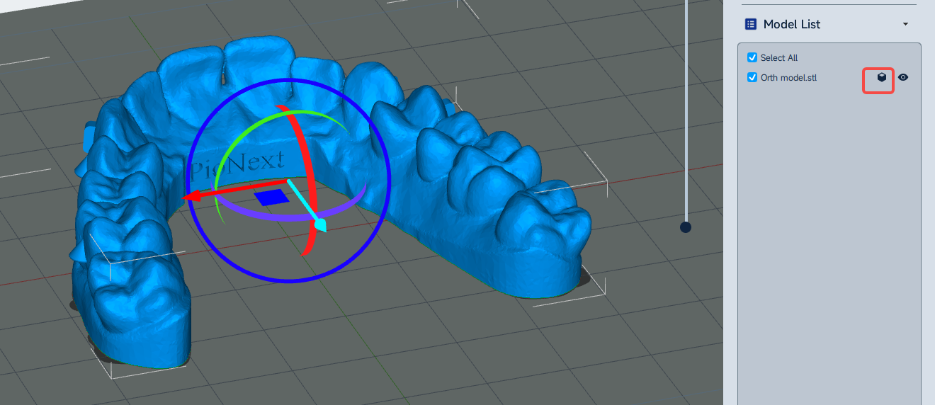
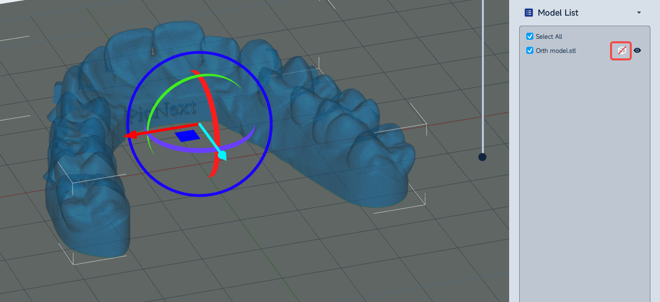
Translucent Display: Click the corresponding icon to temporarily make the model translucent for better observation of internal structures.
-
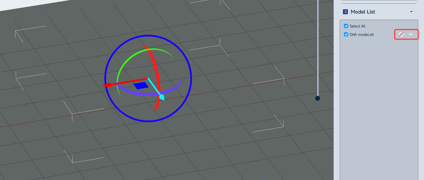
Hide: Click the corresponding icon to hide the selected model(s). Hidden models cannot be edited or sliced.
¶ Tolerance Compensation
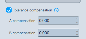
- Adjust the tolerance of inner and outer contours to optimize part fit. After clicking, you can set A‑compensation or B‑compensation. See Chapter 2, Section 2.4 – Advanced Settings for detailed adjustment methods.
¶ Print Preview
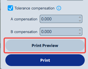
- Preview the printing effect of each layer, support distribution, etc., before printing, allowing intuitive assessment of issues (e.g., insufficient supports, model exceeding platform).
After clicking the "Print" button, the software will slice: it converts the model into code recognizable by the printer.
After slicing, you can customize the file name. It is recommended to use a short combination of English letters and numbers.
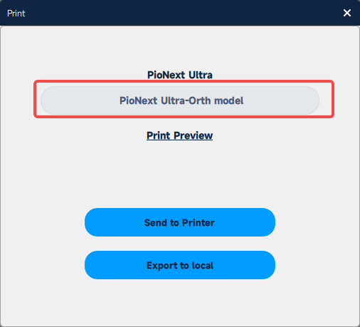
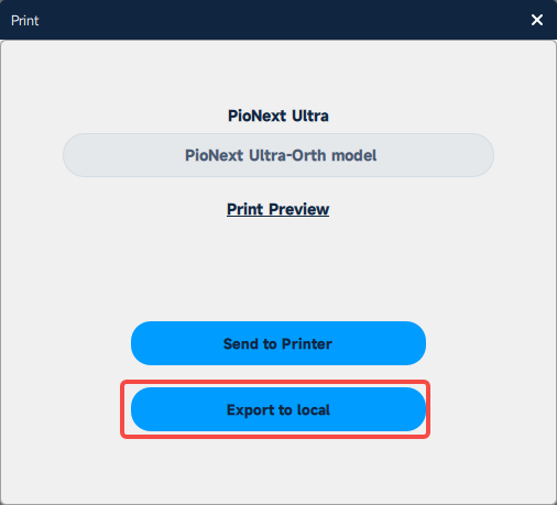
- Export to Local: Save the sliced file to local storage (can be copied to a USB drive for later manual import to the printer).
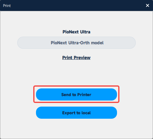
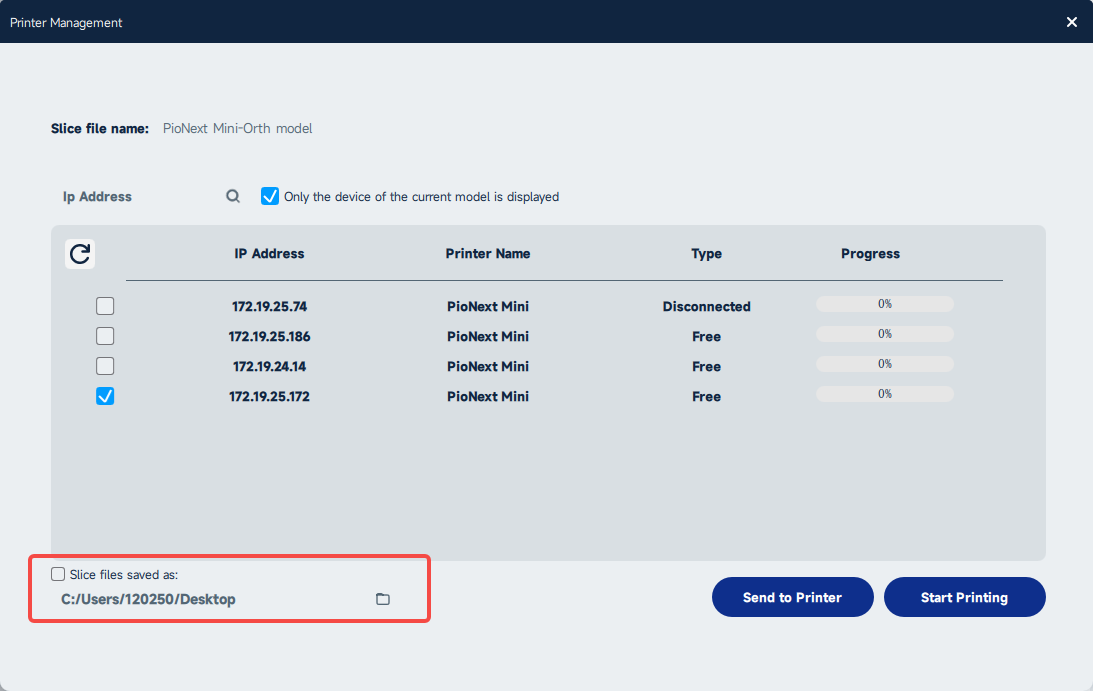
- Send to Printer: Directly send the sliced file to a printer through the LAN.
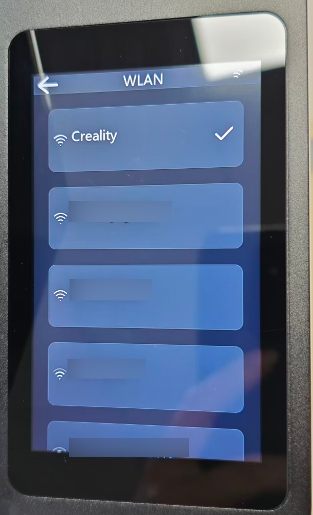
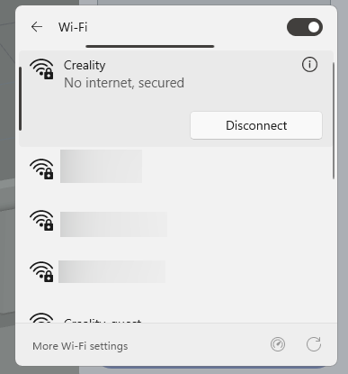
- Before sending a sliced file, make sure that the computer and printer are connected to the same Wi-Fi network
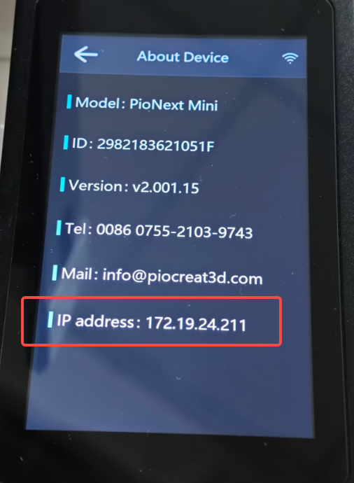
- Find the IP Address in the machine's 'About Device'
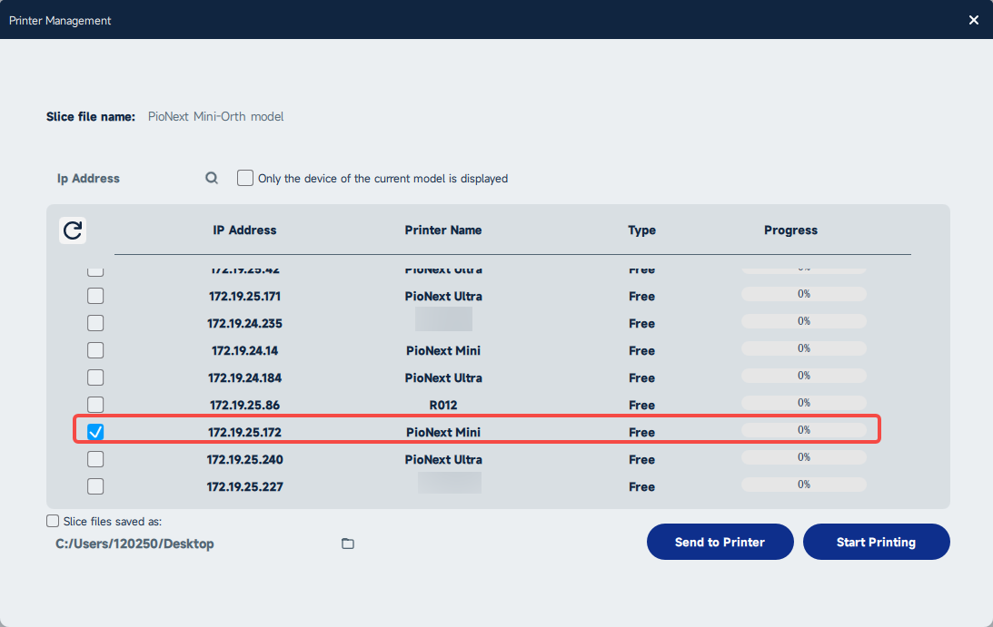
- Find the corresponding IP address in the printer list of the slicing software.
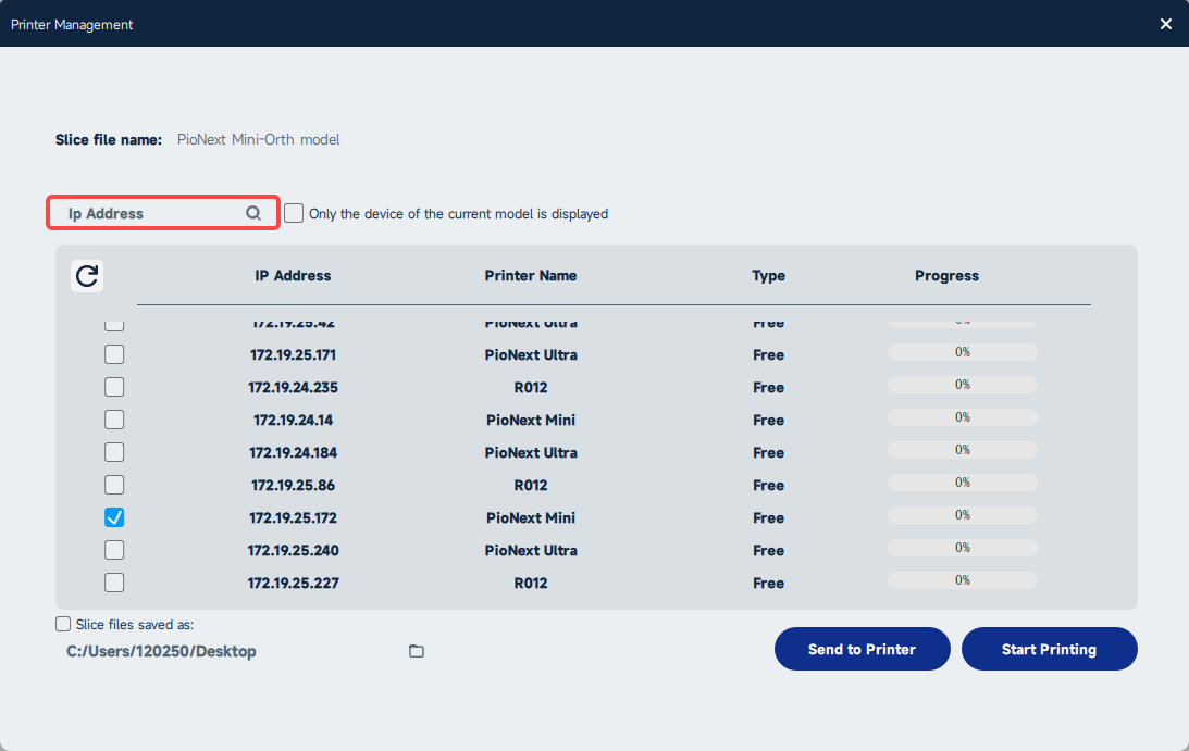
- Directly search for IP Address here
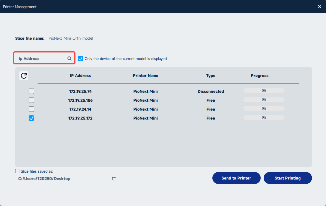
- If the IP Address is not found, try refreshing the list:
- Send to Printer: Only send the sliced file to the machine without starting the print job
- Start Printing: Send the sliced file and start printing directly
- Before sending a sliced file, make sure that the computer and printer are connected to the same Wi-Fi network
Special Precautions: Before starting printing, ensure that the build platform and resin tank are clean to avoid machine damage.
- Sliced File saved as: Save the sliced file to the local disk of the computer while sending it to the printer
¶ 1.5 Bottom Status Bar
The bottom status bar displays predicted information for the current print job, helping you understand print cost and time, and assisting in adjusting the print plan.
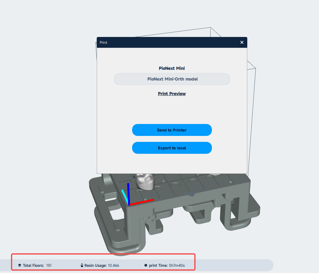
- Total Floors: Total number of layers after slicing
- Resin Usage: Estimated Resin Consumption
- Print Time: Total printing duration estimated based on current parameters
Precautions : The consumable usage and estimated printing time are theoretical estimates, and the actual consumption may vary.
¶ Chapter 2: Print Parameter Settings
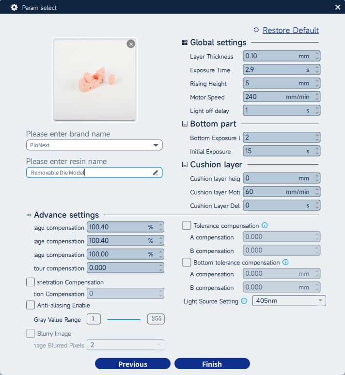
Parameter settings directly affect print quality, speed, and model quality. Beginners can start with default parameters and then fine‑tune based on print results. After adjustments, it is recommended to save the settings as a parameter set for future reuse. The following explains each parameter category in detail, including definitions, adjustment tips, and notes.
¶ 2.1 Global Settings
¶ Layer Thickness
Layer thickness is the height of each sliced layer, in mm, directly affecting print accuracy and speed. Smaller layer thickness gives higher accuracy but longer print time; larger layer thickness gives faster print speed but may lose surface details. Choose the appropriate layer thickness based on model accuracy requirements.
- Recommended : For beginners, the default is 0.05mm, balancing precision and speed; for detailed models (such as jewelry), use 0.03-0.04mm, and for large ornaments, use 0.06-0.1mm;
¶ Exposure Time
The time each layer of resin is exposed to UV light for curing, in seconds (s). Too short exposure leads to insufficient curing and weak interlayer adhesion; too long exposure may cause over‑curing and oversized dimensions. Different resin types require different exposure times.
Additional Note : If parts fit too tightly (over‑cured, dimensions too large), reduce exposure time. If fit is too loose (under‑cured, dimensions too small), increase exposure time.
¶ Rising height
After each layer is completed, the travel height by which the printing platform rises. It is necessary to ensure that the rising height is sufficient to prevent the newly cured layer from adhering to the release film.
- Recommended: For beginners, the default is 8-10mm. Larger build platforms require higher lift heights. If layers are missing, increase by 1‑2mm each time until the issue is resolved.
¶ Motor Speed
The moving speed of the Z‑axis motor during printing, in mm/min. Too fast may cause motor step loss and degraded print quality; too slow increases print time.
- Adjustment Tips: Higher speed reduces print time but may cause resin splashing and model cracking; lower speed improves stability but extends print time.
- Recommended: 180-300mm/min by default for beginners, and 120-180mm/min for large models or fragile models.
¶ Light-off delay
The interval time from the end of printing each layer to the start of printing the next layer, with the unit of seconds (s), aims to allow the uncured resin to flow back.
- Adjustment Techniques: When the resin has high viscosity and poor fluidity (e.g., in low-temperature environments), the delay should be increased (2-3s); when the resin has good fluidity, the delay can be reduced (0-1s);
- Recommended Parameters: For beginners, the default is 1s, and fine-tuning based on resin fluidity is sufficient.
¶ 2.2 Initial/Bottom Parameters
The bottom layers are the initial layers directly in contact with the build platform. They need strong adhesion to ensure print stability and prevent detachment – key to printing success.
¶ Bottom Exposure Layers
Set the number of layers using the "initial exposure time", i.e., the first N layers at the bottom of the model, to be printed with a longer exposure time to enhance adhesion.
- Adjustment Techniques: Too many layers increase printing time and result in a larger bottom layer size; too few layers lead to insufficient bottom layer adhesion, making the model prone to detachment;
- Recommended Parameters: For beginners, the default is 4 layers; for large and heavy models, it can be increased to 5-6 layers; for small and detailed models, it can be reduced to 2-3 layers.
¶ Initial exposure time
The exposure time corresponding to the bottom exposure layers, usually longer than normal print exposure, to enlarge the cured area of the bottom layers and enhance adhesion to the platform.
- Adjustment Techniques: Longer initial exposure gives stronger adhesion but greater dimensional deviation on the bottom. To reduce deviation, you can raise the model and print with supports.
¶ 2.3 Cushion Layer
The Cushion layer is an auxiliary parameter positioned between the bottom layers and normal layers. By reducing motor speed and other means, it can protect printed models and the printer unit, improve printing stability, and minimize resin splashing.
¶ Cushion layer height
The height at which the platform begins to decelerate and buffer when rising/falling, with the unit being mm.
- Adjustment Techniques: The higher the cushion layer height, the better the buffering effect, the less resin splashing, but the printing time increases slightly;
- Recommended parameters: For beginners, the default is 2-3mm; if resin splashing is severe, it can be increased to 3-4mm.
¶ Cushion layer motor speed
The platform moving speed of the cushion layer is in mm/min, which is slower than the normal motor speed.
- Adjustment Techniques: The slower the speed, the better the buffering effect, reducing resin splashing and stress on the model;
- Recommended Parameters: For beginners, the default is 30-50mm/min, which is 50%-70% of the normal motor speed.
¶ Cushion layer light-off delay
The light-off delay effect during the cushion layer stage, with the unit of seconds (s), is slightly longer than the normal light-off delay.
- Adjustment Techniques: The longer the delay, the more complete the resin reflow, reducing resin splashing during the buffer phase;
- Recommended Parameters: For beginners, the default is 1.5 - 2s, which is 0.5 - 1s longer than the normal light-off delay.
¶ 2.4 Advanced Settings
Fine-tune the printing accuracy, model size, and curing effect to address detailed issues during printing, suitable for users with some experience; beginners can use the default values first.
¶ Shrinkage Compensation
Pre‑compensate model dimensions based on the resin’s curing shrinkage characteristics to reduce dimensional deviation caused by shrinkage.
- Adjustment Techniques: If the model contracts in the X-axis direction (size is too small), increase the X-axis shrinkage compensation value; the same applies to the Y-axis and Z-axis contractions, adjust the corresponding axis parameters respectively
¶ XY Axis Counter Compensation
Compensate contours in the horizontal plane, suitable for resins with significant XY shrinkage, to optimize part fit.
- Adjustment Techniques:
- Positive value (+): Plugging and unplugging is too loose, the model contour expands outward, the printed thickness increases, offsetting resin contraction
- Negative value (-): Plugging and unplugging is too tight, the model contour contracts inward, the printed thickness becomes smaller, offsetting light overexposure and edge diffusion
¶ Anti-aliasing
When enabled, it can reduce the jaggedness at the edges of the model and improve surface quality. The higher the anti-aliasing level, the smoother the edges.
Generally, the pixel precision of a print screen above 8K is already high enough, so anti-aliasing can be turned off
¶ Tolerance Compensation
Adjust the independent compensation of the outer and inner contours of the model, which is mostly used for hollow structural parts such as dental crowns and sleeves, to optimize the fitting accuracy of model parts, and is consistent with the "tolerance compensation" function in the right sidebar.
- Adjustment Techniques:
- A Positive value:Inner contour contracts inward → Inner diameter decreases (inner wall thickens)
- A negative value: The inner contour expands outward → the inner diameter crown increases (the inner wall becomes thinner)
- B Positive value: Outer contour expands outward → Outer diameter increases
- B Negative value: Outer contour contracts inward → Outer diameter decreases
¶ Bottom tolerance compensation
Independently compensate for dimensional tolerances of the outer and inner contours of the contact platform at the bottom of the model.
- Adjustment Techniques:
- Positive value of A:Inner contour of the bottom layer contracts inward; Negative value of A:Inner contour of the bottom layer expands outward
- Positive value of B:the outer contour of the bottom layer expands outward; Negative value of B:the outer contour of the bottom layer contracts inward
¶ Light Source Settings: 385/405nm
Select the UV light source wavelength of the printer to adapt to different types of resin
- Adjustment Techniques: Select the corresponding wavelength according to the resin instructions
Precautions : If the wavelength of the light source does not match the resin, it will result in insufficient resin curing and printing failure. Be sure to choose correctly.