¶ 1.Download and install Falcon Design Space
Check the link for the current version of Falcon Design Space and download the version that matches your computer.
- Windows
- MacOS
When your download is complete, find the file in the Downloads folder. On Windows and MacOS, simply double-click on the downloaded file.
¶ Minimum computer requirements
The default startup size of Falcon Design Space is 1440*1000, so it is required that the resolution of the user's computer is not lower than 1440*1000.
¶ Windows installation
Double-click the installer (*.exe) to start the installation program and follow the process.
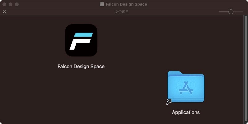
¶ MacOS installation
Installing Falcon Design Space on macOS is the same as most macOS software. After downloading the DMG file, open it (usually by double-clicking on it) and drag Falcon Design Space into Applications.
¶ 2. Beginner's Documentation
¶ Laser
Function Description:
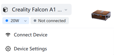
Equipment List: Click on the equipment name to expand all of Creality's laser engraving equipment; users can click on the equipment to select.
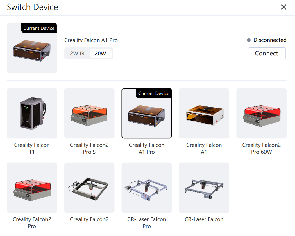
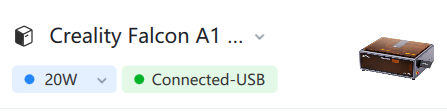
Connecting the device: The laser device supports automatic connection to the computer via USB; you can also manually click to connect.
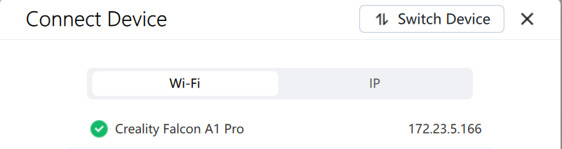
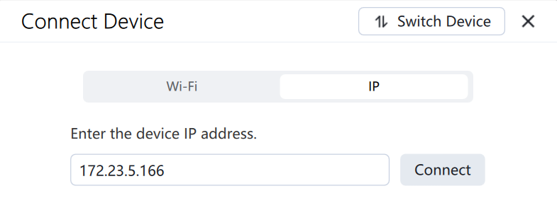
Connecting devices via Wi-Fi: Some devices support Wi-Fi connectivity. Click the Wi-Fi connection button and select the Wi-Fi device to connect; or manually enter the device's IP address to connect.

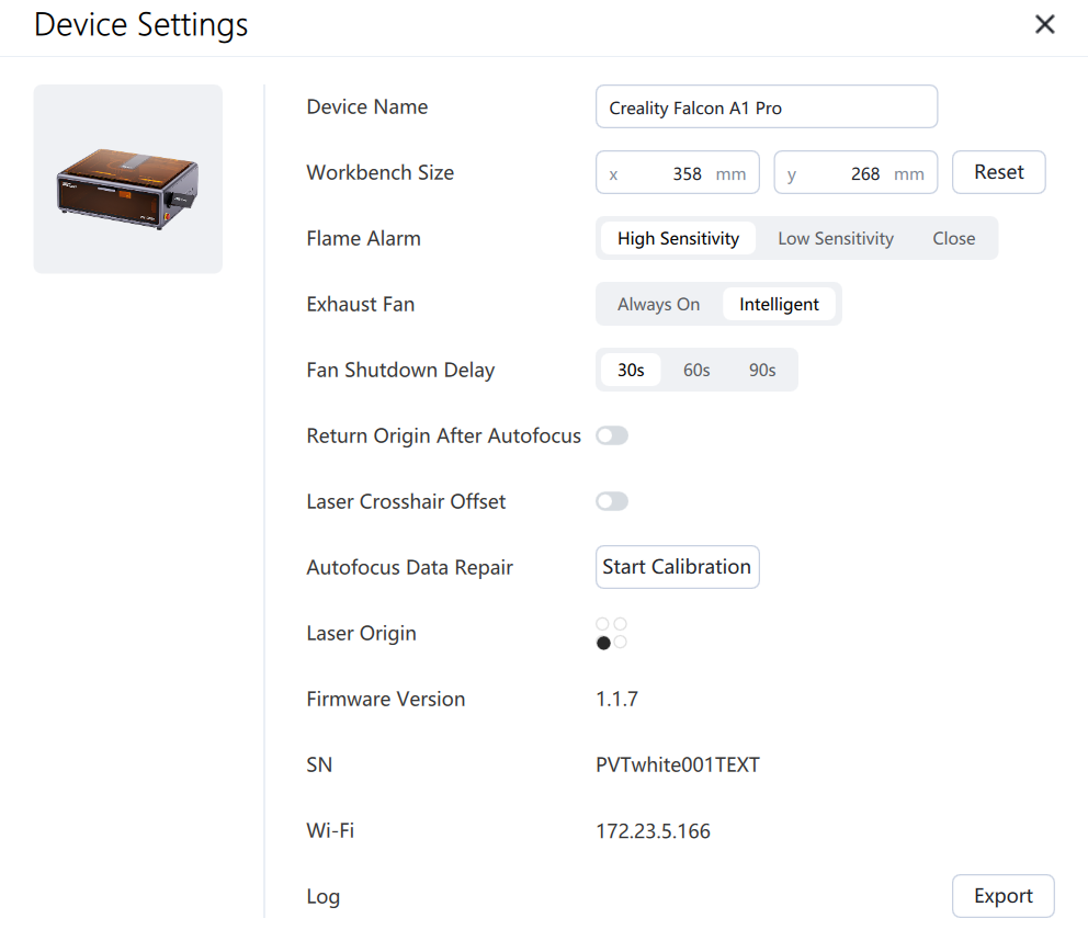
Device Settings: Clicking Device Settings allows you to view and change the processing range, laser origin settings, modify some functions, set the laser pointer offset (suitable for personal use with external third-party crosshair self-positioning devices), view the firmware version, and some machines support log export functionality.
¶ Basic usage
¶ Creating Shapes
Falcon Design Space's shape creation tools allow you to create simple shapes. Select a tool from the left toolbar, such as the Ellipse, Rectangle or Polygon tool. After selecting a tool, left-click in the canvas and drag the mouse to resize the shape being created. When dragging, the Shift key will force the shapes to have the same width and height, so you get circles and squares instead of ellipses and rectangles.The Ctrl key centers the shape at the starting point instead of dragging it from corner to corner. Release the mouse button to complete the shape. For text, select the Text tool and then enter the text content in the edit window on the right. the text in the canvas is synchronized for modification.
¶ Importing files
Supported import formats: SVG, DXF, PNG, JPG, BMP, JPEG
You can import files into Falcon Design Space in several different ways.
1.Click the file upload button on the left side of the workbench page;
2.Upload files using the keyboard shortcut Ctrl+I;
3.Drag and drop files onto the canvas to import.
4.Copy and paste to canvas
¶ Moving and resizing artwork
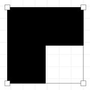
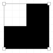
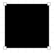
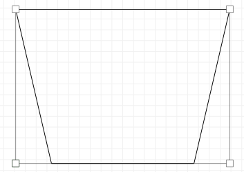
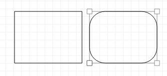
Once you have elements in Falcon Design Space, the next step is usually to place or resize them. When one or more elements are selected, they will enter the selected state and you will see various “tool handles” appear on the outside of the selection, as shown below;
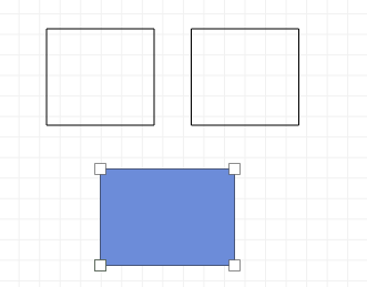
Grabbing any of the four corners lets you resize an element from that corner, by default using the other corner as an anchor point for uniform resizing. Holding down Ctrl (Command build on Mac) switches the anchor point to the center, so the center of the object stays in place when resizing. Holding down the Shift key adjusts the width and height independently, rather than locking them together.
Grabbing any of the four side handles lets you adjust the width or height of your selection, and the Ctrl/Command key switches to the center anchor point, just as it does for corner sizing. When moving, the status bar shows both the absolute position of the selection being moved and the relative distance it was moved.
You can also edit the position, rotation, and size of the drawing in the Basic Information toolbar.

¶ Group
When you create shapes in Falcon Design Space, they are independent of the other shapes you create. Sometimes it's handy to treat a bunch of things as a whole, to make sure they maintain their relative positions and sizes when you move them around. In Falcon Design Space, this is called a group. If you select two or more shapes and click the Group button or press Ctrl+G, you will create a new object containing the original shapes. To ungroup to edit individual elements, select a group of shapes and click the Ungroup button or press Ctrl+Shift+G.
¶ Sculpting layers
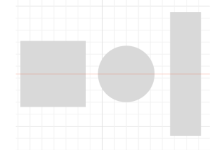
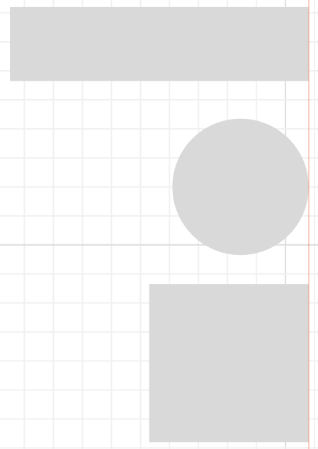
When a vector file is imported into Falcon Design Space, it defaults to the first layer, which is black by default.
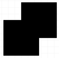
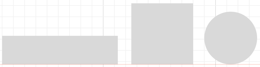
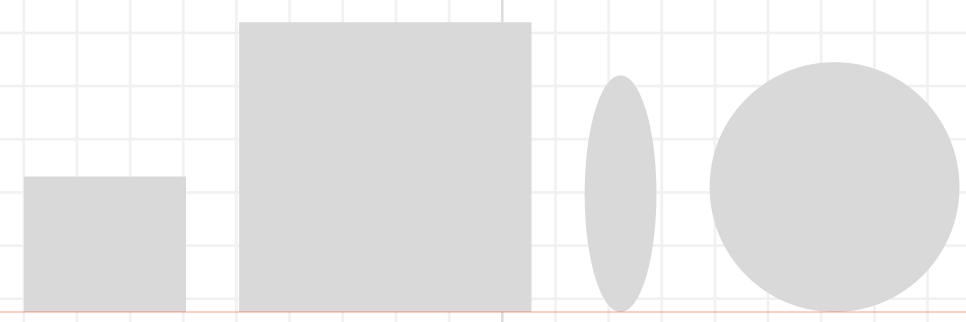
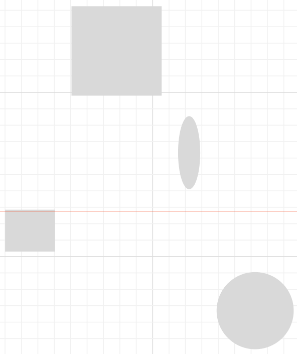
Layers in Falcon Design Space are used to assign different settings to shapes in a design. For example:
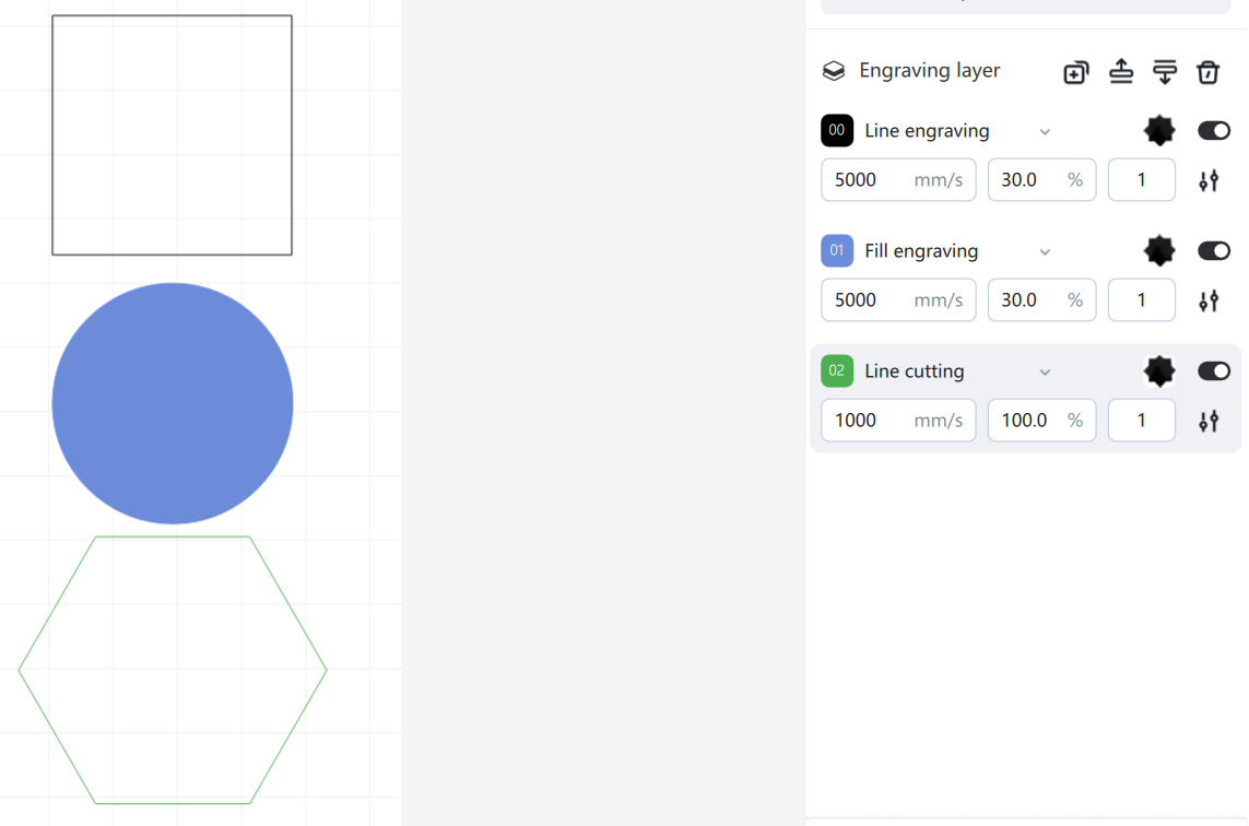
In the design above, the laser control is used for line engraving of rectangles on layer 00, for filling engraving of circles on layer 01, and for line cutting of polygons on layer 02.
¶ Make a simple print process
We will show step by step how to create a small and simple project, from start to finish, showing how to use some basic editing tools.
This project will make a simple name tag, cut around the letters, ideally made from basswood board.
¶ Creating Text
In the left toolbar of the Workbench, click the “Text” button shown below.

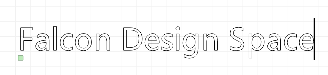
Next, click somewhere in the middle of the Edit window (workspace) to get the cursor and enter the text:
Click the “Select” button or press the “ESC” key to enter the selection mode.
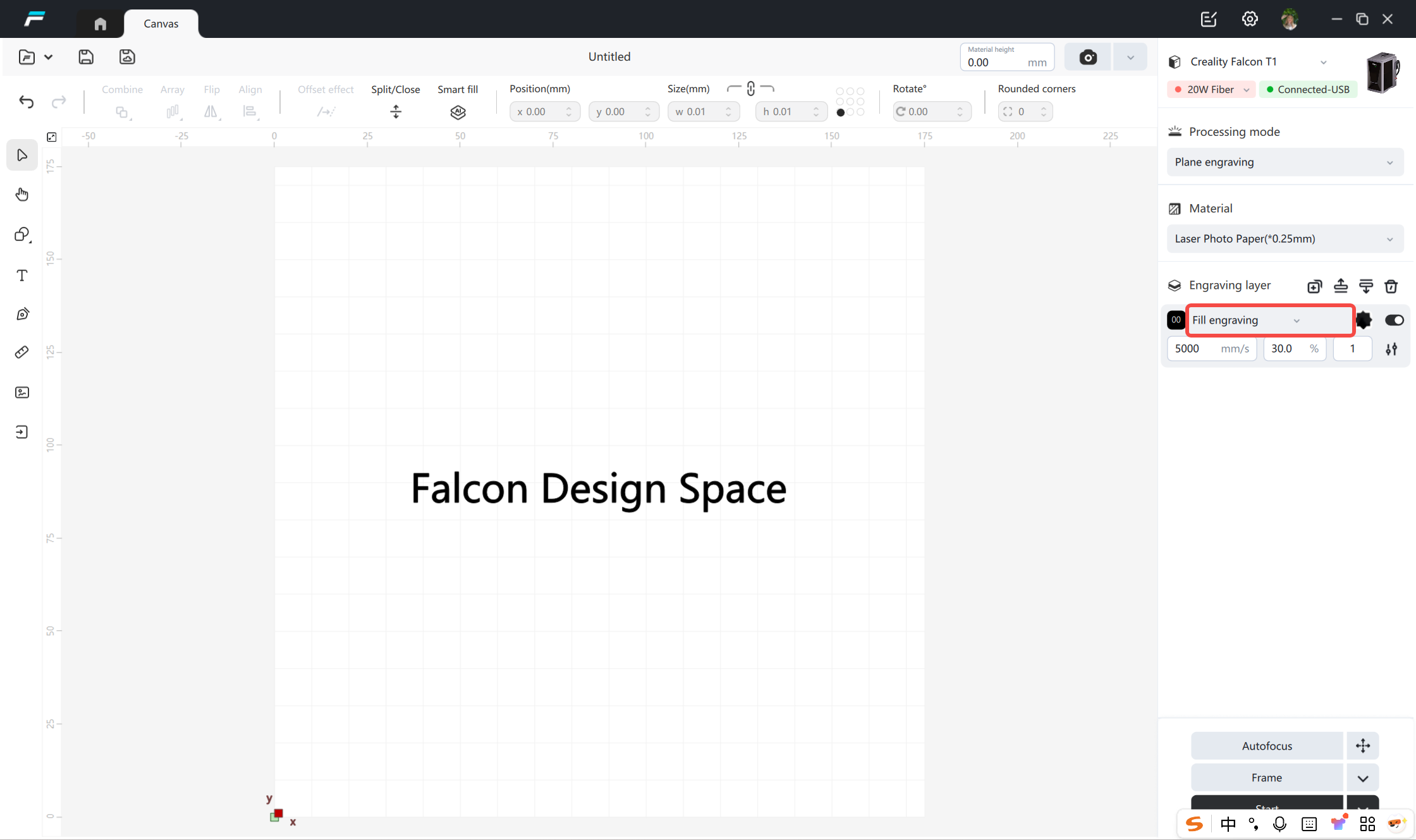
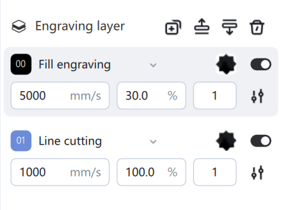
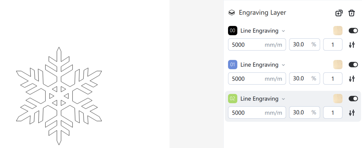
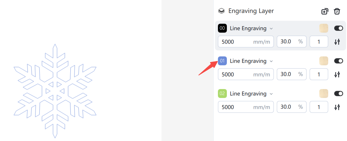
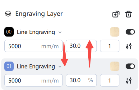
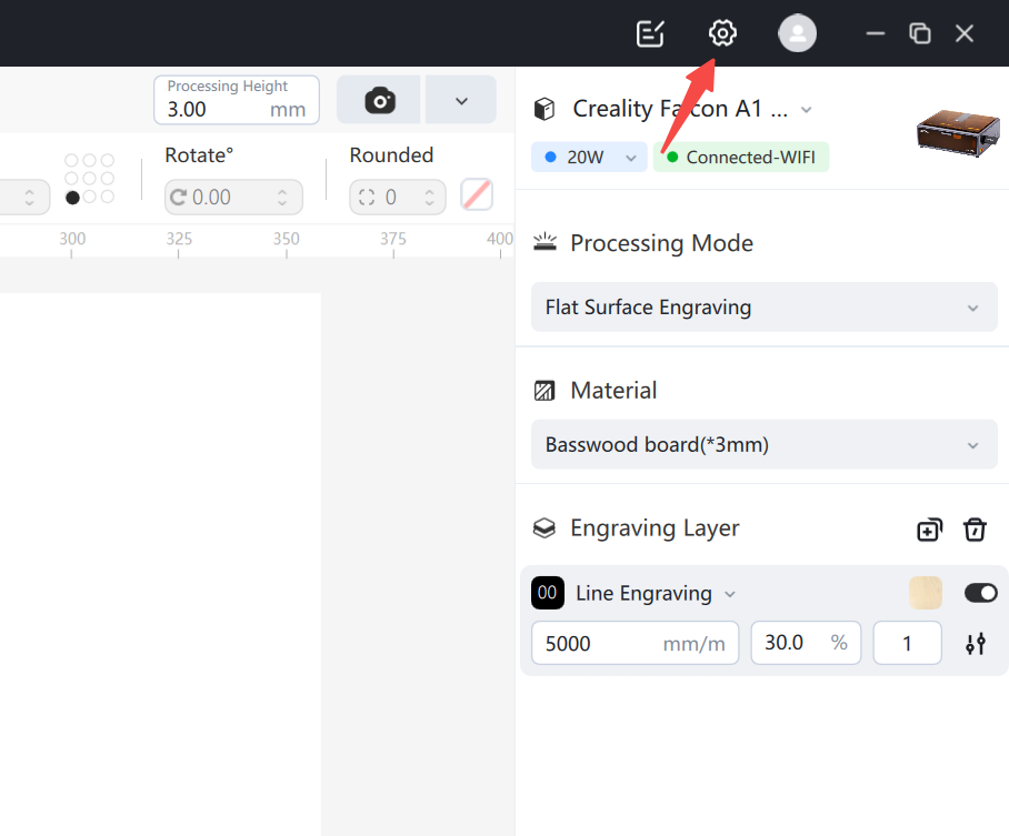
After you add the text, you can adjust the print parameters in the “Engraving Layers” list, modify its engraving mode, speed, power, number of times, output and other settings:
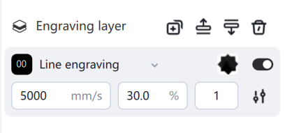
This engraving layer tells us that the engraving mode is line engraving, the speed is 5000mm/m, the power is 30%, and the number of prints is 1. Printing will be performed according to these parameters. The power, speed, and number of prints for this engraving layer will vary depending on the selected laser equipment and the material being processed.
¶ Changing Text Attributes
Make sure you are currently in selection mode, with the Select button highlighted. Click on the text to bring it to the selected state. This is shown in the image below:
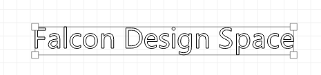
Drag the handle to modify the size, position or orientation of the selected object.
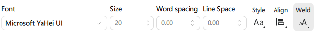
The Text Settings bar appears when the text is selected, as shown in the following figure:
¶ Undo/Restore
If you make a change you don't like, you can undo it by clicking the Undo button on the toolbar (or pressing Ctrl+Z/Edit-Undo on the menu). If you decide you like it, you can also do a restore operation on it (Ctrl+Y/Edit-Restore on the menu).
¶ Changing layer settings
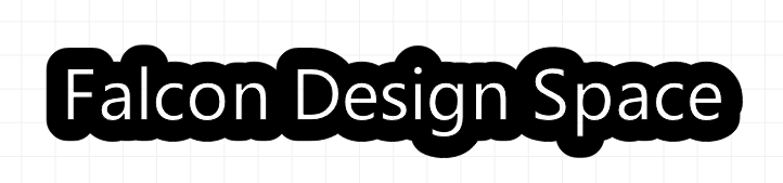
Instead of Outline Text, you want Solid Fill. In the “Engrave Layer” window, change the engrave mode to “Engrave with Fill”.
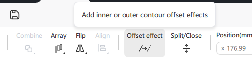
¶ Adding Outlines: Offset Effect
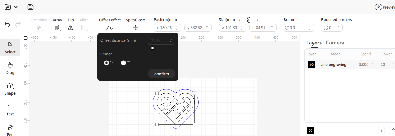
After selecting the text, click the “Offset Effect” button, as shown below:
The “Offset Effect” pop-up window will appear, as shown below:
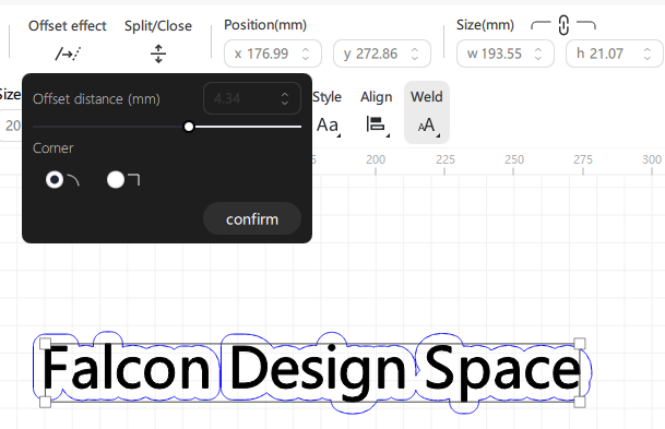
The offset effect outlines the selected shape by setting the offset distance (positive value outward, negative value inward), and after adjusting it to a satisfactory effect, click the Confirm button to generate the shape.
¶ Changing the engraving mode
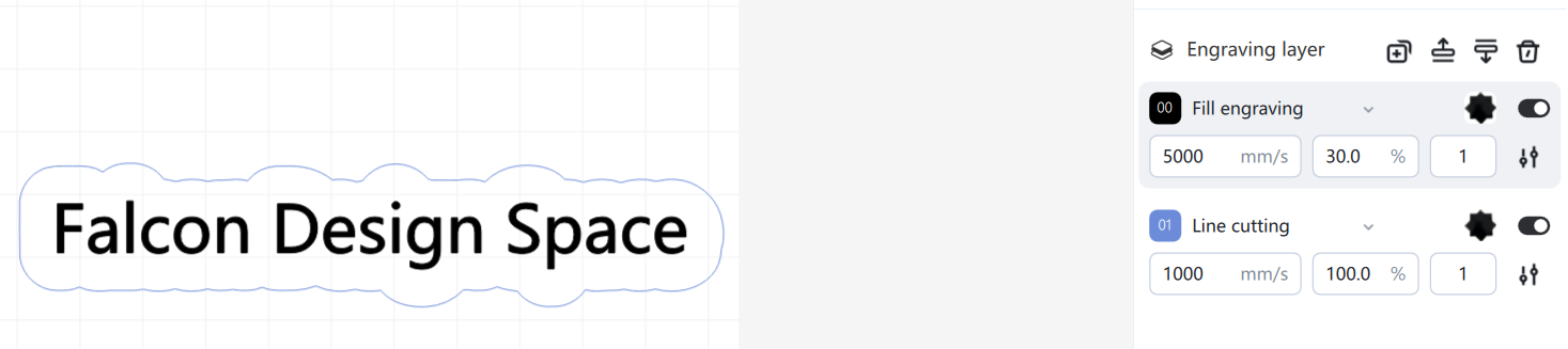
Click the Add button to add an engraving layer. Select its engraving mode as “Line Cut”.
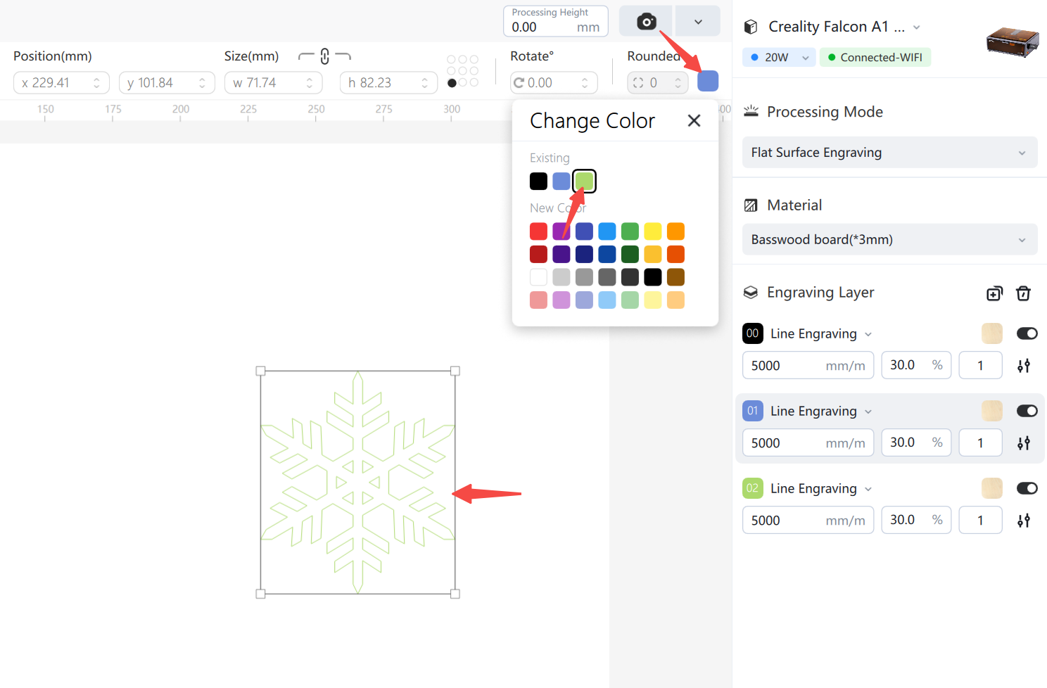
Now, using the selection tool, select the outline shape you just created. Then, in the sculpting layer, right-click the color swatch on layer "01" to switch the outline shape to layer 01, as shown in the image below:
¶ Engraving parameters
Engraving parameters include speed, power, and number of times. These parameters will give you the recommended values according to your currently selected laser equipment and processed materials, which can be used directly, or can be modified in the engraving layer list by yourself if required.
¶ Material
Clicking on the Machining Material drop-down box displays a library of material parameters in which you can switch machining materials, as shown in the following figure:
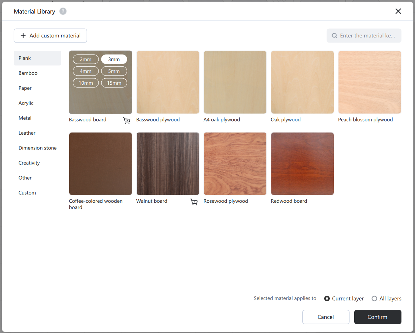
After selecting a material, you can choose to apply the material to all layers or the current layer:
- All Layers: Changes the default material to the currently selected material. All added layers and newly added layers will use the currently selected material.
- Current layer: Only modify the processing materials used in the current layer;
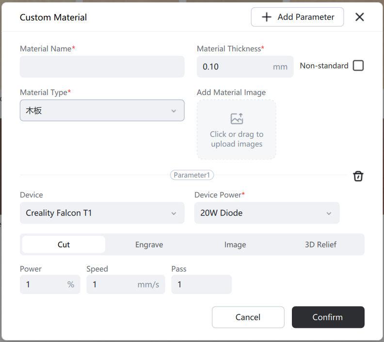
In addition to using the official preset materials, you can also create custom materials to use, save the sculpting parameters, and reuse them for future purposes.
¶ Processing Settings
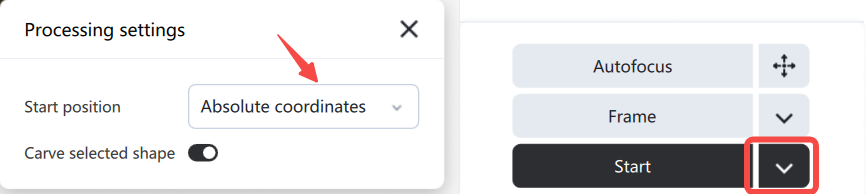
Starting position: You can choose between the current position or absolute coordinate mode for printing.
¶ absolute coordinates
The page grid seen in the workbench window represents your machine's working area. Anything placed within this area will be cut at the corresponding location on the machine. An automatic reset is performed before printing absolute coordinates to prevent printing failures due to incorrect current coordinate information.
¶ Current location
When you click the start button, the engraving operation will begin from the current position of the laser head.
Use the job origin control to tell Falcon Design Space how to position the engraving job relative to the laser.
¶ Start printing
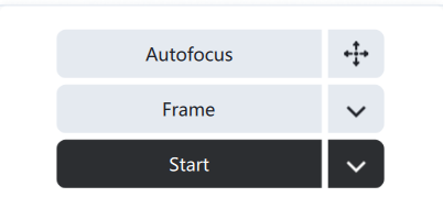
Before starting the job, you need to perform automatic focusing (supported by some devices) and border walking (rectangular border, rubber band border) operations to ensure that the artwork can be engraved on the printing material. The laser border walking path will vary depending on your current selected start position mode (absolute coordinates, current position). After confirming that everything is correct, click the "Go to Processing" button .
Processing path: You can choose from four printing modes: automatic planning, from near to far, from inside to outside, and by layer sequence. Depending on the design, you can select the corresponding mode and adjust the printing order to optimize printing time.
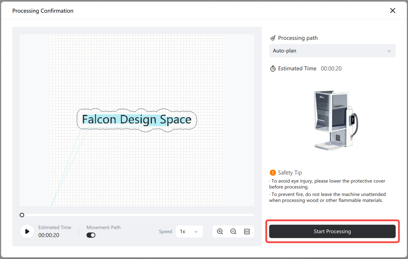
Click "Start Processing" to begin laser processing. If any problems occur during laser processing, click the "Pause/Stop" button to terminate the operation. After clicking "Pause," the button will change to "Resume." Click the "Resume" button to continue completing the unfinished work.
After completing the work, if the engraving is too deep or too dark, you can increase the speed or decrease the power in the engraving layer; if the cut is unsuccessful, you can decrease the speed or increase the power. If you don't need to modify the settings, you can try cutting again.
¶ 3. User interface and functionality
¶ Falcon Design Space UI
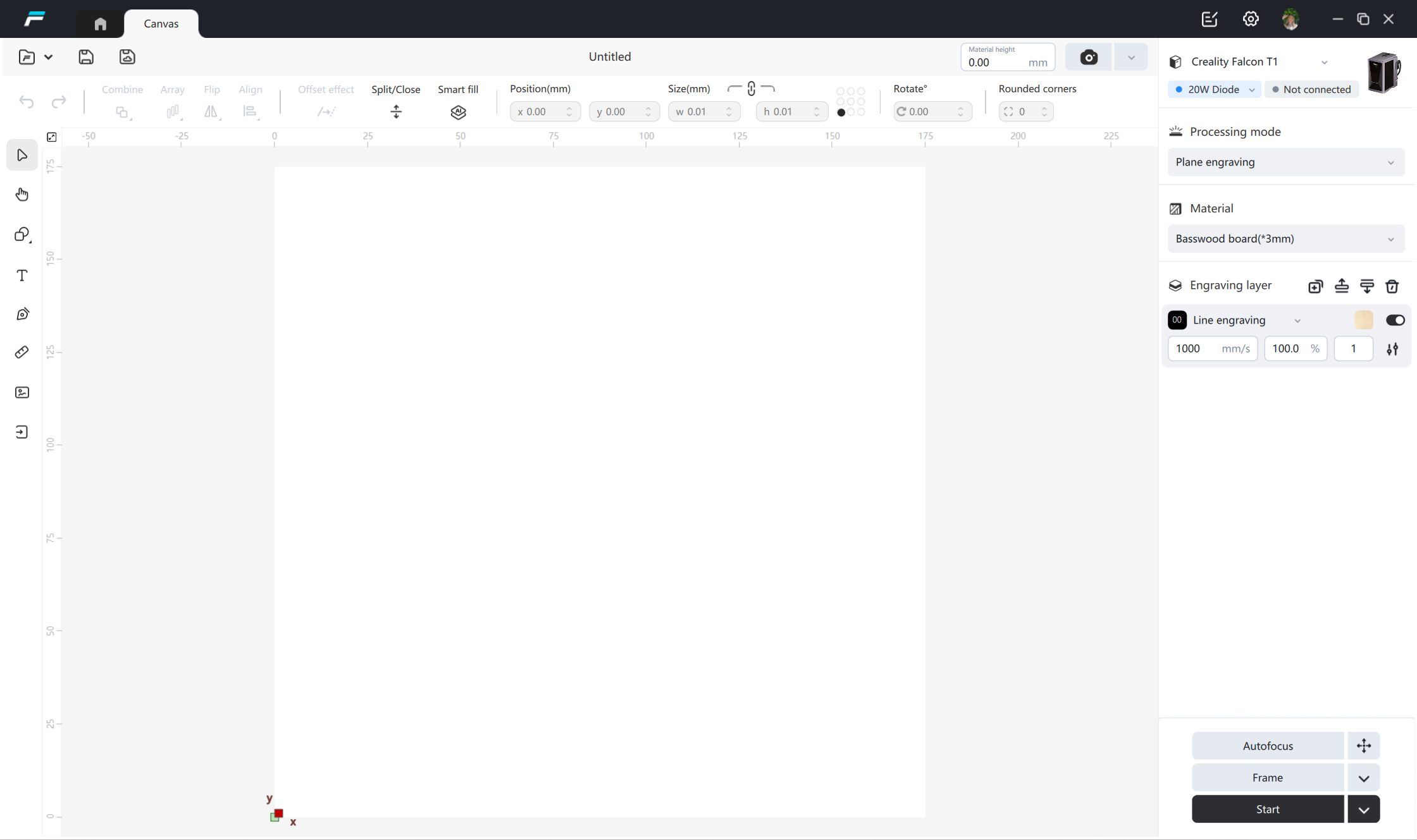
This is the default layout for Falcon Design Space windows.
¶ Menu
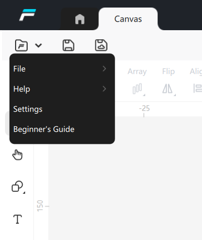
¶ File
- Create a new project
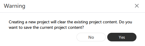
Clicking on 'New Project' in the 'File' menu will clear all current projects and create a new one.
Functional Description: When creating a new project, it will check if the current project has not been saved, and a pop-up window will prompt as follows:

Click 'Yes' to open the path save window and perform the project save operation.
Click 'No' to clear existing project information and directly create a new project.
Click the "Close" button in the upper right corner to close the pop-up window, cancel the creation of the new project, and continue operating in the current project.
- Open the project
To open an existing or saved project file, click "Open Project" on the "File" menu
Functional Description: Open the project, display the path selection pop-up window, select the project file to open, and the pop-up window prompt is as follows:
Click 'Confirm' to overwrite the existing project content.
Click 'Cancel' to close the warning pop-up window and no longer proceed with opening the project.
Click the "Close" button in the upper right corner to close the warning pop-up window and no longer proceed with opening the project.
- Save project
Functional Description: After clicking, a path selection pop-up will appear. After setting the storage path and name, save the project as a * * *. fds format file.
- Save project as
Functional Description: Save the project as another file.
- Export vector diagram
Functional Description: Export the design drawings from the canvas in SVG format.
- Save G-code
Functional Description: Keep the current design as a "GCode" file, which can be used for offline operations through an IF card.
- Save color G-code
Function Description: Saves the current design as a color gcode file. On some machines that support external screens, after loading the gcode file using a USB flash drive, a thumbnail of the design can be viewed on the screen for further processing.
- Run G-code
Open the file directory, select the G-code file, send the G-code file to the engraving device, and start the printing task directly.
¶ Help
- Teaching videos
Jump to YouTube
- Common problems
Frequently Asked Questions about Jumping to the Official Website
- Join the community
Join the community, jump to the Facebook community
- Problem feedback
- Shortcut keys
Click to display a shortcut key pop-up window, where you can view all shortcut keys.
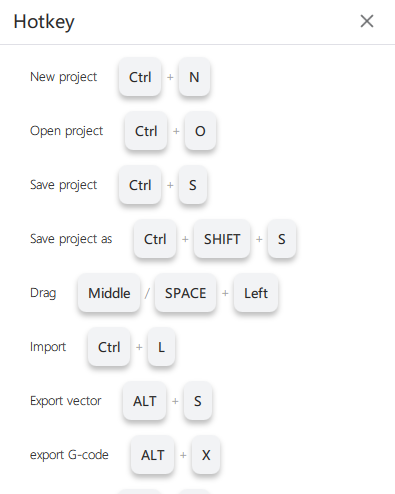
The statistics of Falcon Design Space shortcut keys are shown in the following table:
|
Shortcut keys |
Windows |
Mac |
|
New project |
CTRL+N |
COMMAND+N |
|
Open project |
CTRL+O |
COMMAND+O |
|
Save project |
CTRL+S |
COMMAND+S |
|
Save project as |
CTRL+SHIFT+S |
COMMAND+SHIFT+S |
|
Drag |
Middle/SPACE+Left |
Middle/SPACE+Left |
|
Import |
CTRL+L |
COMMAND+L |
|
Export vector |
ALT+S |
ALT+S |
|
Save G-cdoe |
ALT+X |
ALT+X |
|
Run G-code |
ALT+N |
ALT+N |
|
Undo |
CTRL+Z |
COMMAND+Z |
|
Restore |
CTRL+Y |
COMMAND+Y |
|
Select |
ESC |
ESC |
|
Select all |
CTRL+A |
COMMAND+A |
|
Cut |
CTRL+X |
COMMAND+X |
|
Copy |
CTRL+C |
COMMAND+C |
|
Paste |
CTRL+V |
COMMAND+V |
|
Paste in place |
CTRL+D |
COMMAND+D |
|
Delete |
DELETE |
DELETE |
|
Group |
CTRL+G |
COMMAND+G |
|
Ungroup |
CTRL+SHIFT+G |
COMMAND+SHIFT+G |
¶ Set up
Open the Design Space settings window.
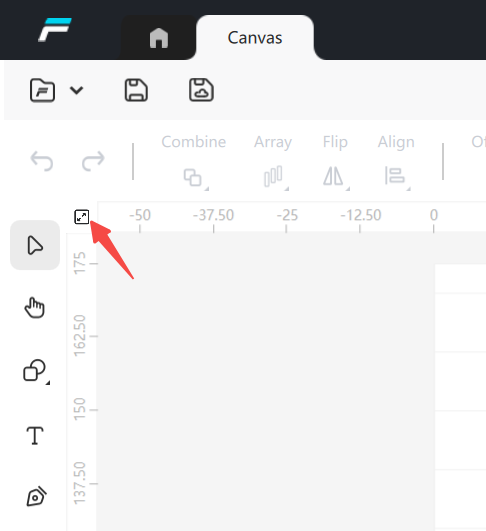
¶ Fit to screen
Function Description: Clicking this button will restore the canvas to its default size so that you can see the full workspace.
¶ Top Toolbar
The main toolbar of Falcon Design Space allows you to quickly access commonly used functions such as undo, restore, adapt to the screen, preview, align, distribute, and more;

¶ Undo
Functional Description: To undo the last editing operation on the current file, click on the “Undo” icon/Ctrl+Z in the upper left corner.
¶ Restore
Functional Description: To redo the last editing operation on the current file, click on the “Restore” icon/Ctrl+Y in the upper left corner.
¶ Combine
- Unite
Functional Description: Click “Unite” in the “Combine” menu to combine two shapes into a single outline.
- Subtract
Functional Description: Click “Subtract” in the “Unite” menu to cut out a graphic from another graphic, there are two kinds of cases: A minus B and B minus A. When you use this function once, you can exclude the top layer. If the effect of cutting does not meet the expectation after using Exclude Top Layer once, you can use Undo to cut it again, so that it will change from A minus B to B minus A.
- Intersect
Functional Description: By clicking “Intersect” in the “Unite” menu, you can combine two shapes into a single outline and delete the parts that do not intersect.
- Exclude
Functional Description: Subtracting the overlapping area before the shapes, Falcon Design Space will by default exclude the shapes in the same engraving layer from intersecting, at this time the shapes are still separated, the user can drag them around, and after manually triggering the exclusion of intersections, the shapes will be merged into a whole.
¶ Array
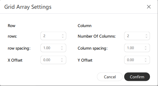
- Grid Array
Functional Description: Click “Grid Array” in the “Array” menu to create an array or grid of objects in the workspace. A window will open allowing you to set the parameters of the array or grid.
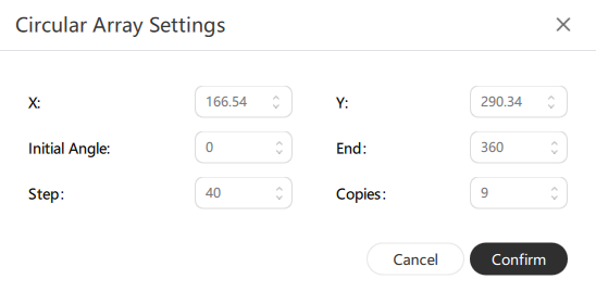
- Circular Array
Functional Description: Click “Circular Array” in the “Array”menu to create an array or grid of objects in a circle in the workspace. A window will open allowing you to set the parameters of the array or grid.
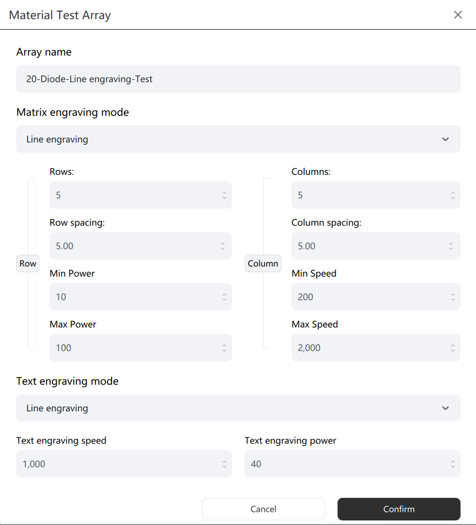
- Material testing array
Function description: Click on 'Material Test Array' in the 'Array' menu to create a test array of objects in the workspace. A window will open, allowing you to set the parameters for the material test array.
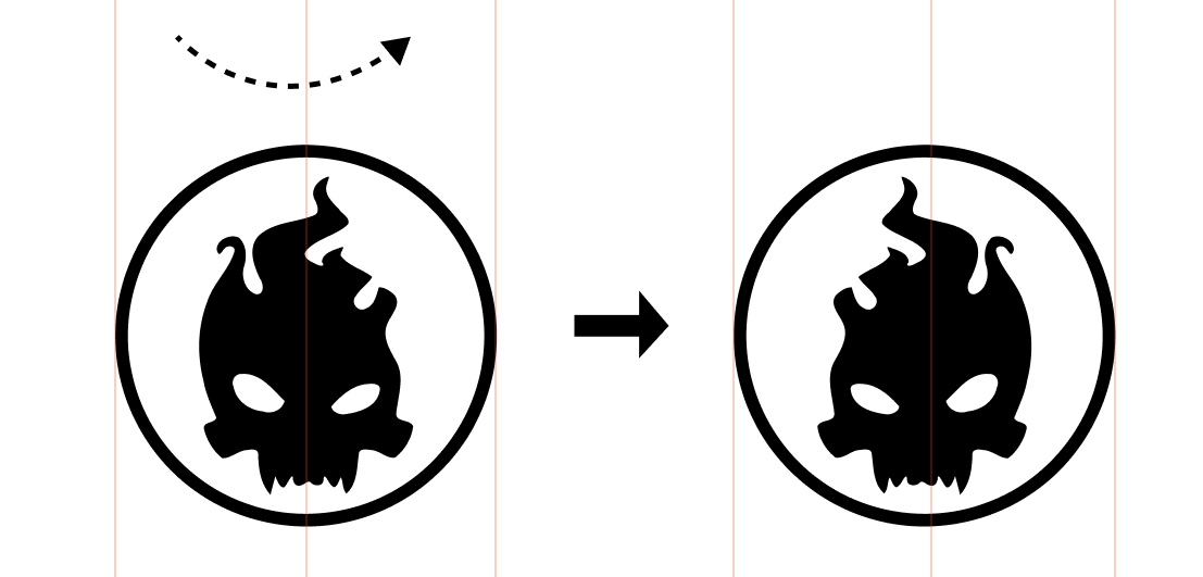
¶ Flip
- Flip Horizontal
Functional Description: “Flip Horizontal” flips the selected objects in the workspace horizontally.
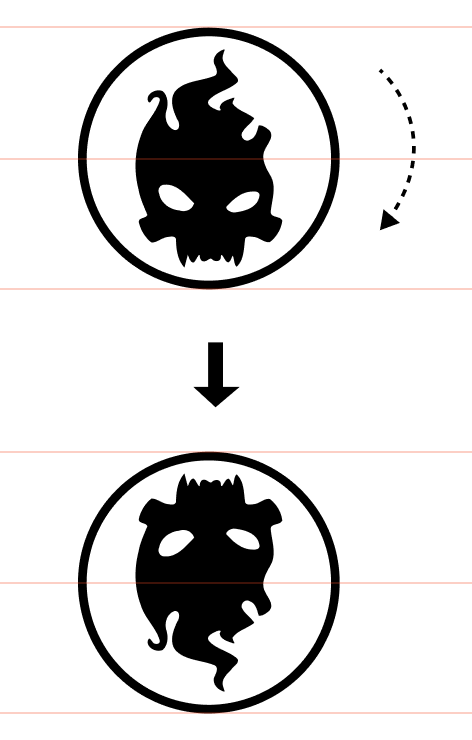
- Flip Verical
Functional Description: “Flip Vertical” flips the selected objects in the workspace vertically.
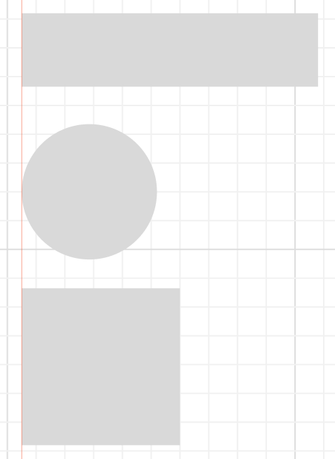
¶ Align
- Align Left
- Functional Description: “Align Left” aligns the selected objects in the workspace to the left, with the box centered on the last drawn shape and the point centered on the last selected shape.
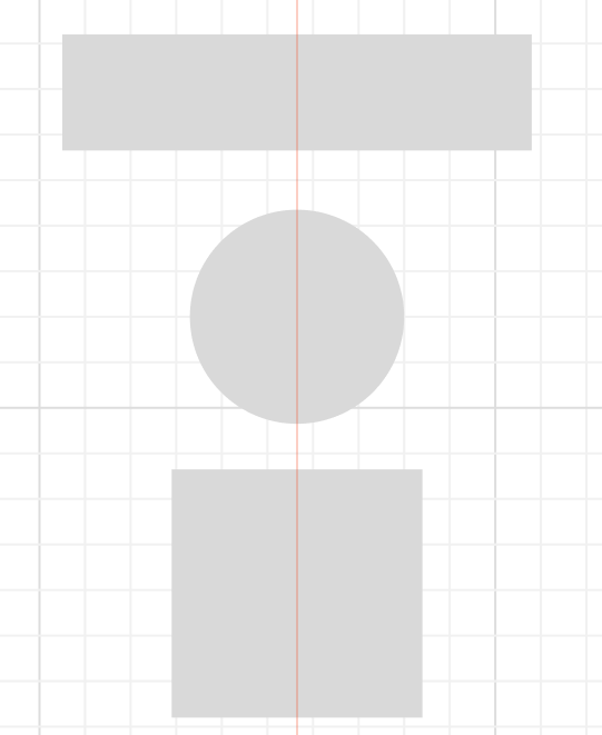
- Align vertically
Functional Description: “Align Vertical”aligns the selected objects in the workspace vertically, with the box centered on the last drawn shape and the point centered on the last selected shape.
- Align horizontally
Functional Description: “Align horizontally” aligns the selected objects in the workspace vertically, with the last drawn shape as the center of the box, and the last selected shape as the center of gravity.
- Align Right
Functional Description: “Align Right” aligns the selected objects in the workspace to the right, with the box centered on the last drawn shape and the point centered on the last selected shape.
- Align Top
Functional Description: “Align Top”aligns the top of the selected objects in the workspace, with the last drawn shape as the center of the box, and the last selected shape as the center of gravity.
- Horizontal Alignment
Functional Description: “Horizontal Alignment”aligns the selected objects in the workspace horizontally, with the box centered on the last drawn shape and the point centered on the last selected shape.
- Align Bottom
Functional Description: “ Align Bottom”aligns the selected objects in the workspace to the bottom, with the last drawn shape as the center of the box, and the last selected shape as the center of gravity.
- Distribute vertically
Functional Description: “Horizontal Distribution” distributes the selected objects in the workspace horizontally with the same interval between each object.
- Distribute horizontally
Functional Description: “Distribute horizontally” distributes the selected objects in the workspace vertically with the same interval between each object.
¶ Offset effect
Functional Description: The offset effect outlines the selected shape by setting the offset distance (positive value to the outside, negative value to the inside), and then clicking the Confirm button to generate the shape after adjusting it to a satisfactory effect.
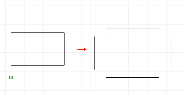
¶ Split/Close
- Shape separation
Functional Description: “Shape Separation” splits a closed shape, such as a closed rectangle, into four segments by clicking Shape Separation;
- Stroke separation
Functional Description: “Line Split” splits a shape into two shapes by straight lines and locks, ignores images and text when splitting, and only works on vector shapes;
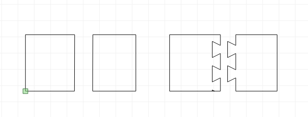
- Shape closing
Functional Description: “Shape Closure” closes the unclosed lines into a shape by the numerical closure distance;
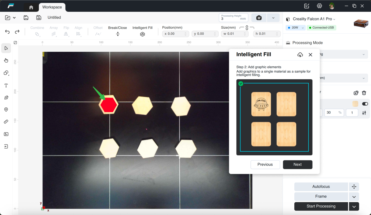
¶ Smart Fill
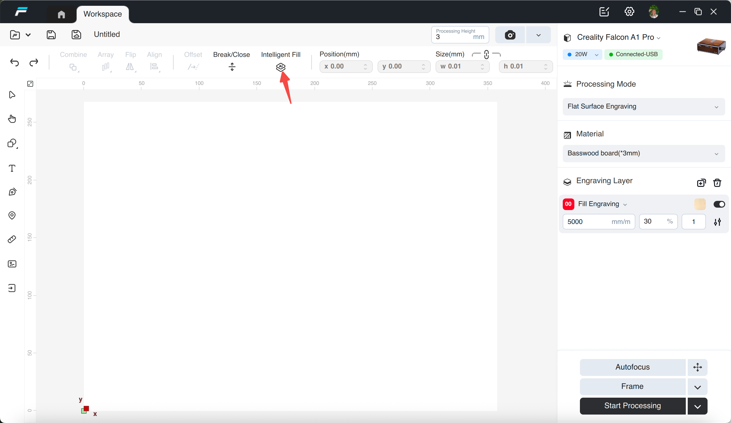
Function description: Intelligently identify the same material on the photo and fill the same design with one click;
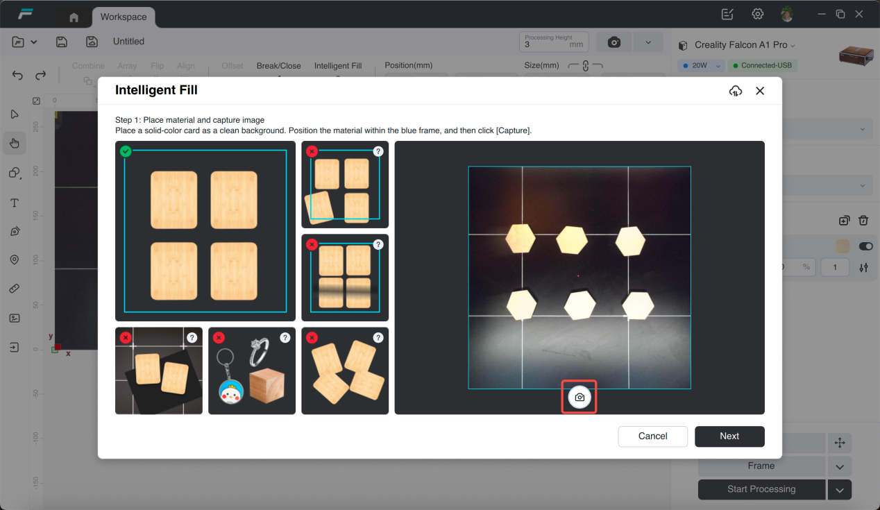
Prerequisites:
1. The camera calibration status is calibrated;
2. Please place the material in the center as much as possible to ensure good and uniform light in the photo;
3. When the color of the material is close to that of the base plate or the material is small, it is recommended to use solid color cardboard to cover the base plate;
4. If the material is reflective, has different shapes, is hollow, is too small, has shadows, has gradient colors, etc., it may lead to low filling accuracy;
5. The filling target size must be consistent;
instructions:
1.After placing the target material, click the "Take Photo" button;
2.Place the graphic to be sculpted on the material and adjust its size and position, then click "Next";
3. Select the sample material;
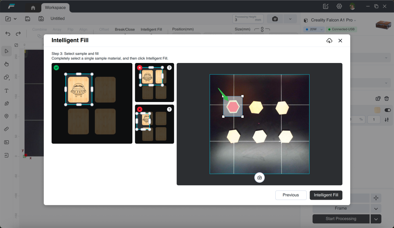
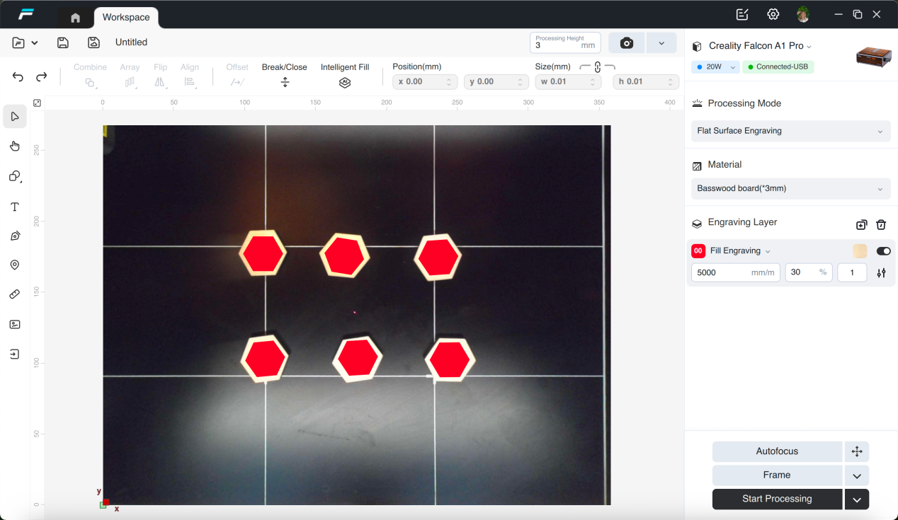
4. Click the "Smart Fill" button;
¶ Position
Function Description: Sets the position of an element on the canvas using x and y coordinates. The origin of the graphic can be set (x:0, y:0), located at the bottom left corner. The unit can be set in the settings, in mm/in.
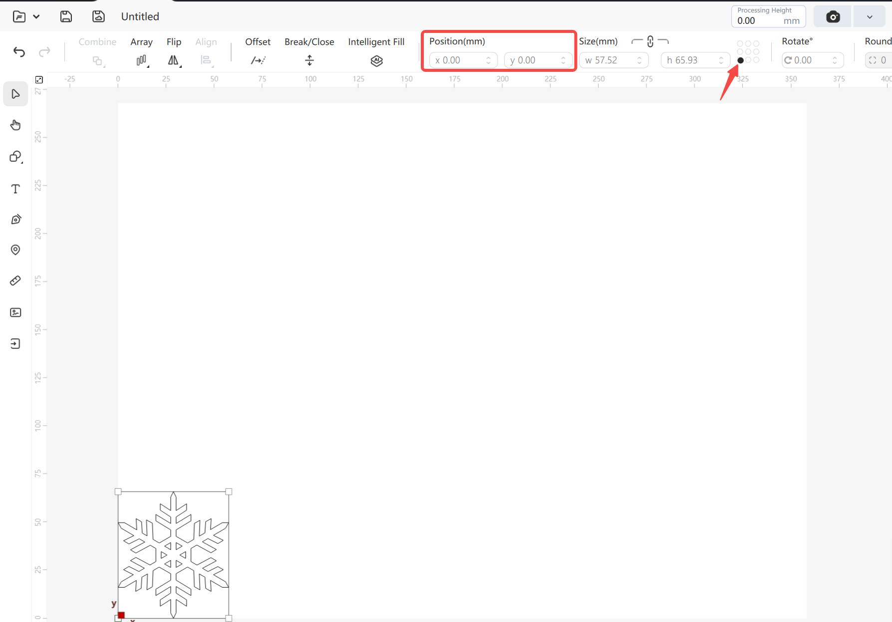
¶ Size
Functional Description: Show or set the size of the object. You can set this unit, mm/in, in Settings.By default, the aspect ratio of an image or object will be locked. You can click the link icon to unlock the ratio so that you can change the width and height of the image or object as needed.
¶ Rotate
Functional Description: Rotates the selected object by angle. Positive values indicate clockwise rotation, while duplicates indicate counterclockwise rotation.
¶ Rounded corners
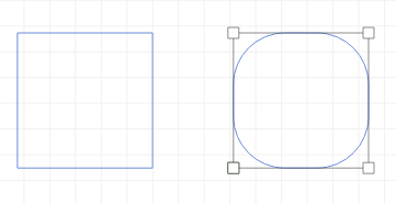
Functional Description: Uniformly sets rounded corners for closed shapes, and supports setting different values for each corner if it is a rectangle drawn by a shape;
¶ left column
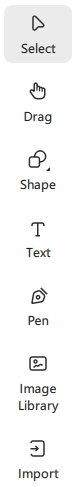
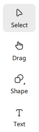
¶ Select
Functional Description:
Click “Select” to select objects in the workspace for moving, scaling, rotating, etc.
Click to select: Clicking on an object (graphic, image, etc.) in the canvas brings the object to the selected state. Closed graphics and images support selection by surface, click on the inside of the object can be selected; non-closed graphics composed of lines, you need to click on the lines to be selected, you can adjust the selection tolerance to select the range.
Box Selection: Click the left mouse button, drag in the canvas, the objects covered by the selection range can be selected together.
Shift+Point Selection: After selecting an object, you can increase the selected object by Shift key.
¶ Drag
Functional Description: Click the “Drag” button, the mouse cursor changes to hand, you can use the left mouse button to grab and drag the view. Support middle mouse button and space+left mouse button.
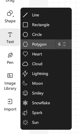
¶ Shape
- Rectangle
Functional Description:
Click the “Shape” menu in the “Rectangle” mouse cursor changed to a cross, you can draw a rectangle in the workspace, press Shift + mouse drag can draw a square, press Ctrl + mouse drag can draw a rectangle from the center, press Ctrl + Shift + mouse drag can draw a square from the center, rectangle can be set for the four corners of different rounded values. Shift+mouse drag to draw a square from the center, rectangle can be set for the four corners of the different rounded values.
- Circle
Functional Description: Click “Circle” in the “Shape” menu to draw an ellipse in the workspace, press Shift+Mouse to drag to draw a circle, press Ctrl+Mouse to drag to draw a circle from the center, press Ctrl+Shift+Mouse to drag to draw a circle from the center. Press Ctrl+Shift+mouse to draw a circle, and press Ctrl+Shift+mouse to draw a square circle from the center.
- Polygon
Functional Description:
Click “Polygon” in the “Shape” menu to draw polygons in the workspace according to the set number of sides, press Shift+mouse to drag to draw orthomorphic polygons, press Ctrl+mouse to drag to draw polygons from the center, and press Ctrl+Shift+mouse to drag to draw orthomorphic polygons from the center. Shift+mouse drag to draw polygons from the center, and Ctrl+mouse drag to draw orthomorphic polygons from the center.
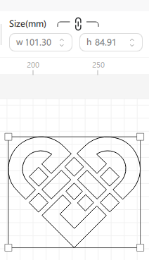
- Special shapes
Functional Description:
There are some SVG shapes preset inside the software, such as “Heart, Cloud, Lightning...”. The SVGs can be imported into the canvas by clicking on the corresponding shape in the Shape menu.
¶ Text
Functional Description: Click the “Text” button to create text in the workspace.

In the Text Settings window, you can
- set fonts
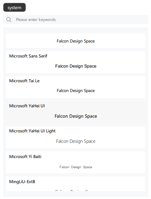
- sets the text sizeset word spacing, line spacing
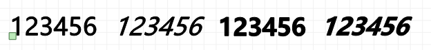
- set text styles (regular, italic, bold, bold italic)
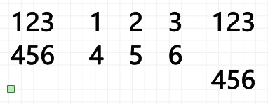
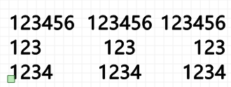
- Alignment: set the alignment of multi-line text, you can choose left, right, center alignment
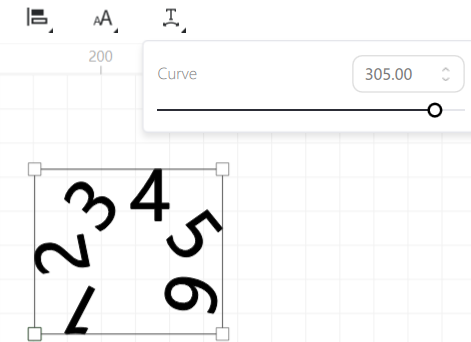
- Curve: The input angle text displays the curve
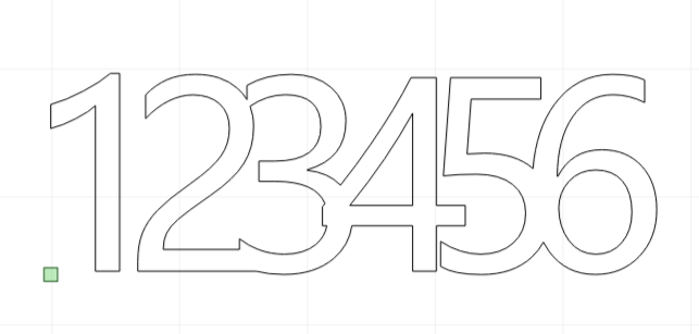
- Welding: Connect areas where the text overlaps.
¶ Pen
Functional Description: By clicking “Vector”, you can draw lines in the workspace, and by clicking to draw a straight line between two points, you can draw a closed graphic. The drawing process is to press the Shift key to draw a straight line at a fixed angle (45°, 90°), and click the right mouse button to disconnect and end the drawing. Drawing a straight line between two line segments allows you to make a line connection.
¶ Image Library
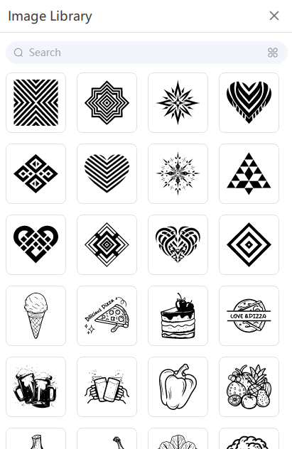
Functional Description:
Falcon Design Space has some SVGs pre-built inside, click on the corresponding shape and it will be imported into the canvas.
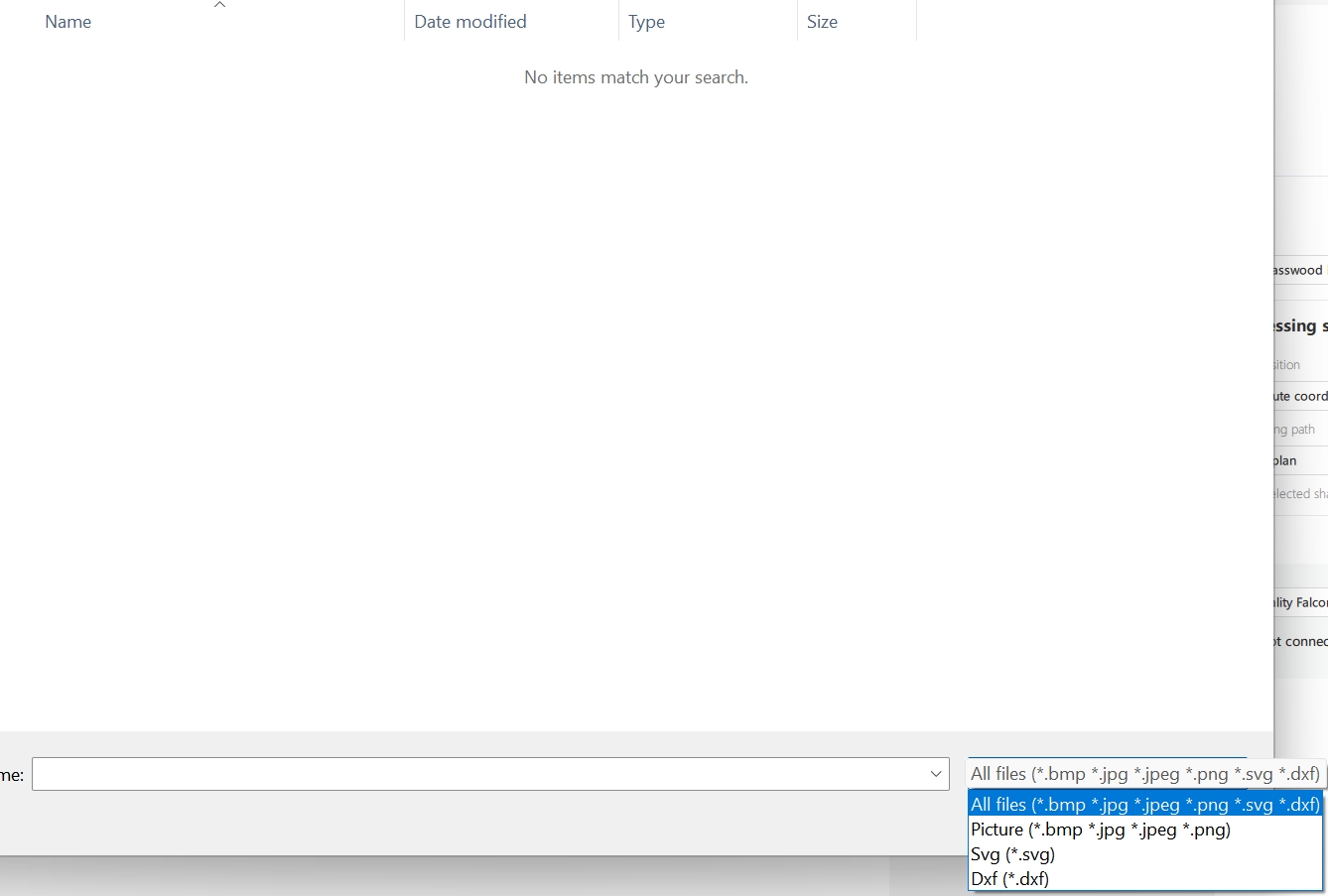
¶ Import
Functional Description:
Show file path popup, import format support: SVG, DXF, PNG, JPG, BMP, JPEG.
¶ Image Settings
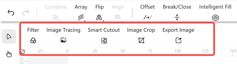
¶ Filter
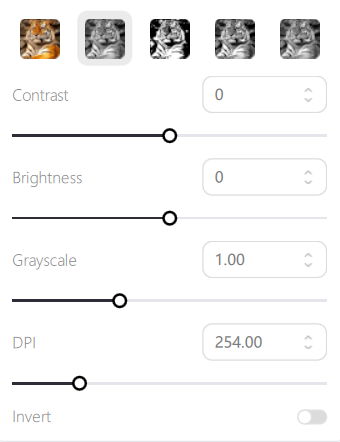
- Filter: Support original, grayscale, black and white, dithering, gray mud, after switching different filters, the image effect is modified in real time according to its set parameters;
¶ Trace Image
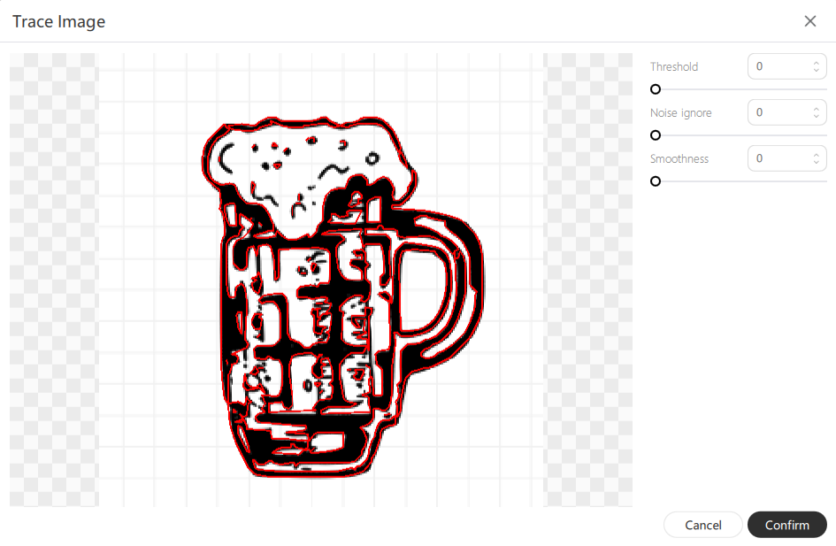
Functional Description:
- Outline Tracing: Click on the “Extract Outline” button to trace the content of the image.
¶ Sculpting layers
The meaning of each column is as follows:
- Layers: Displays the layer name and color. The color of objects in the canvas matches the color of the sculpted layer they belong to. When the mouse moves over a layer, the graphic is highlighted in red on the canvas.
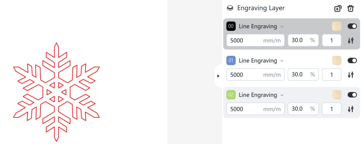
After selecting an object on the canvas, right-clicking the color swatch will switch the selected object to another sculpting layer.
Alternatively, after selecting an object on the canvas, click the color swatch icon in the toolbar above to switch the selected object to another layer.
Note: 1. Image can not be added to the vector layer, vector objects can not be added to the image layer; 2. Image layer can not be created manually, after importing the image, the image layer will be added automatically; 3. Select the image layer, at this time, drawing shapes, will automatically create a vector layer, select the vector layer, import the image to automatically create an image layer.
- Mode: vector layer is divided into line carving, fill carving, line cutting, image carving.
- Speed (mm/m): the movement speed of the laser when you start the engraving job.
- Power (%): the power of the laser when starting the engraving operation.
- times: the number of prints.
- Output: Whether or not it is output as a printout.
The image is shared with the pass count, speed, and power of the engraving layer it is on, and the overscan and fill intervals for the image are set separately in the image editing window.
Below the layer list, you can see the settings of the currently selected layer, where you can set the speed, power, pass count, overscan, and kerf offset. The parameters that can be set are slightly different for different engraving modes.
| Mode | Line engraving | Fill engraving | Line cutting | Image engraving |
| settings item | Speed | Speed | Speed | Speed |
| Times | Times | Times | Times | |
| Power | Power | Power | Power | |
| Overcut | Overscan | Overcut | Overscan | |
| Cut offset | Interval | Cut offset | Interval |
Overcut: When cutting a closed shape, continuing to cut beyond the end of this offset on the last pass.
Cut offset: the amount of offset that is compensated for when cutting closed shapes based on the thickness of the laser.
Overscan: When enabled, an additional movement is added at the beginning and end of each line to avoid burns when engraving filled edges.
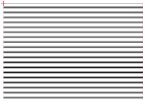
Interval: The distance between each line when performing fill engraving. Below is a preview of the 0.5 and 1mm fill intervals.

¶ Sculpting Layer Operation List
Function Description:
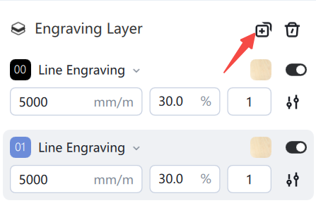
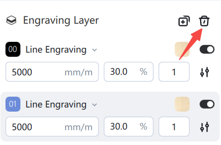
- Added: Added new sculpting layer
- Move Up/Down: Select a layer and drag it up or down with the mouse to reorder the sculpted layers.
- Delete: This button will delete all content on the selected layer.
¶ Processing settings
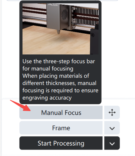
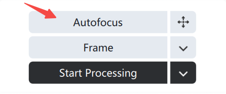
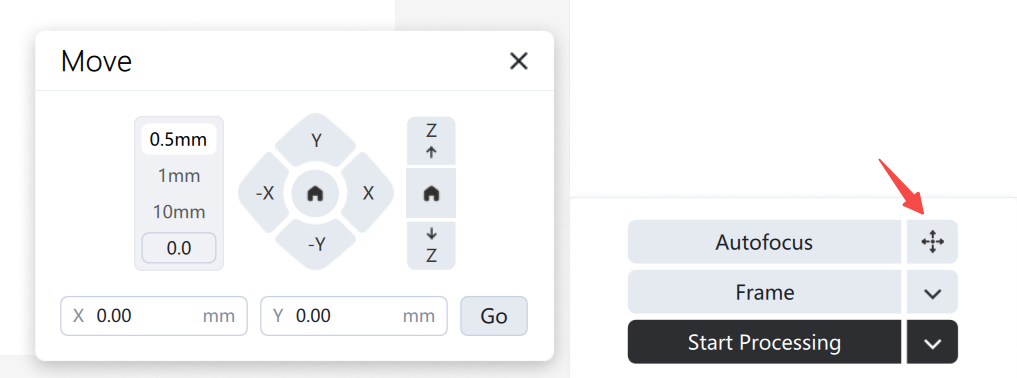
¶ Focus
Different machines are categorized into autofocus and manual focus.
Pop-up settings: Control the machine's X, Y, and Z axis movement and reset.
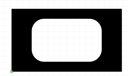
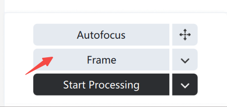
¶ Border
Clicking triggers border tracking, the device status changes to "Border Tracking in Progress" and the button text changes to "Stop Border Tracking". You can end the border tracking state by clicking the button.
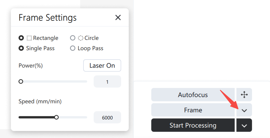
Pop-up settings: Click the drop-down arrow to display the "Border Path Settings" pop-up window;
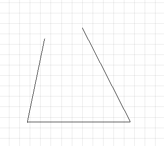
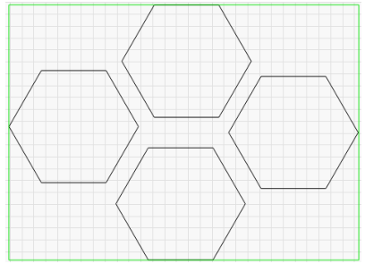
Circular border: Also known as “rubber band framing”, this draws a rubber band shaped path around your design. For hexagonal files, it looks like this:
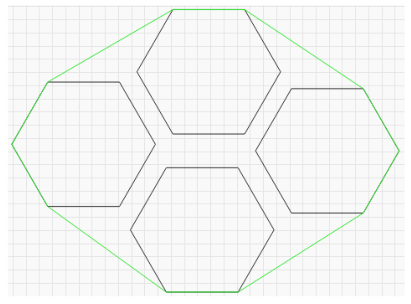
This is useful for arranging irregular shapes where a simple boxed outline would not be appropriate. For example, thin diagonal shapes or triangles.
Rectangular border: Also known as a “bounding box”. This is the smallest rectangle that will completely contain the shape you want to send to the laser.
If my current file is this four hexagons, the green rectangles around them will follow the path of the rectangular frame:
- Single pass: The border movement is executed once;
- Loop Movement : The border movement is executed in a loop until the reset, end, or start button is clicked, at which point it stops.
- Consecration : After clicking the "Consecration" button, the laser head starts emitting light, the button text changes to "Light Off" and the light emission time is displayed. The light emission will be turned off after the countdown ends.
- Power (%) : The laser power emitted when the laser is running along the edge and the output power after clicking the "On" button can be set between 1 and 10;
- Movement speed (mm/m) : The movement speed of the laser head when the movement button is clicked once, as well as the movement speed when moving along the edge, can be set between 1000 and 10000 mm/m;
¶ To process
Pop-up settings: Click the drop-down arrow to display the "Processing Settings" pop-up window;
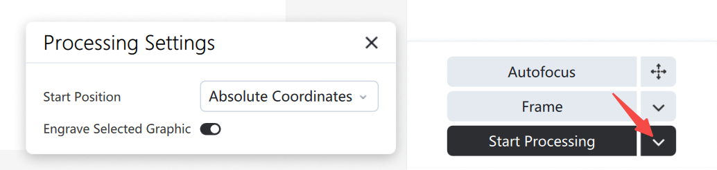
- Current location
Function Description: When you click the start button, the engraving operation will begin from the current position of the laser head.
Use the job origin control to tell Falcon Design Space how to position the engraving job relative to the laser.
- absolute coordinates
Function Description: The page grid seen in the workbench window represents the working area of your machine. Anything placed in this area will be cut at the corresponding position on the machine. An automatic reset operation is performed before printing absolute coordinates to prevent printing failures due to incorrect current coordinate information .
- Carve the selected graphic
Function Description: When the function is enabled, only the graphic selected by the mouse will be processed; when the function is disabled, all graphics in the canvas will be processed by default.
Click "Start Processing" to display the preview window. Fast movement (laser off) is represented by a blue line, and cutting distance (laser on) is represented by a black line. Click the "Run" button to see how the simulated laser will work. You can also drag the progress bar to view the cutting effect at different points in time.
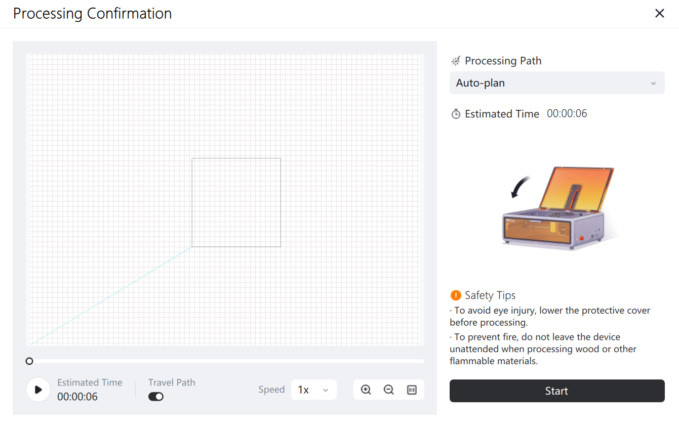
¶ Processing path
- Automatic planning
Functional description: Processing is carried out in the order of carving first and then cutting, from the inside out;
- From near to far
Function description: It moves from near to far, and is relatively fast, making it suitable for single carving or cutting tasks;
- From the inside out
Function Description: A relatively stable processing method, suitable for scenarios where carving precedes cutting;
- By layer
Function Description: Prints from top to bottom according to the display order of the engraved layers list. The printing order can be changed by adjusting the layer order.
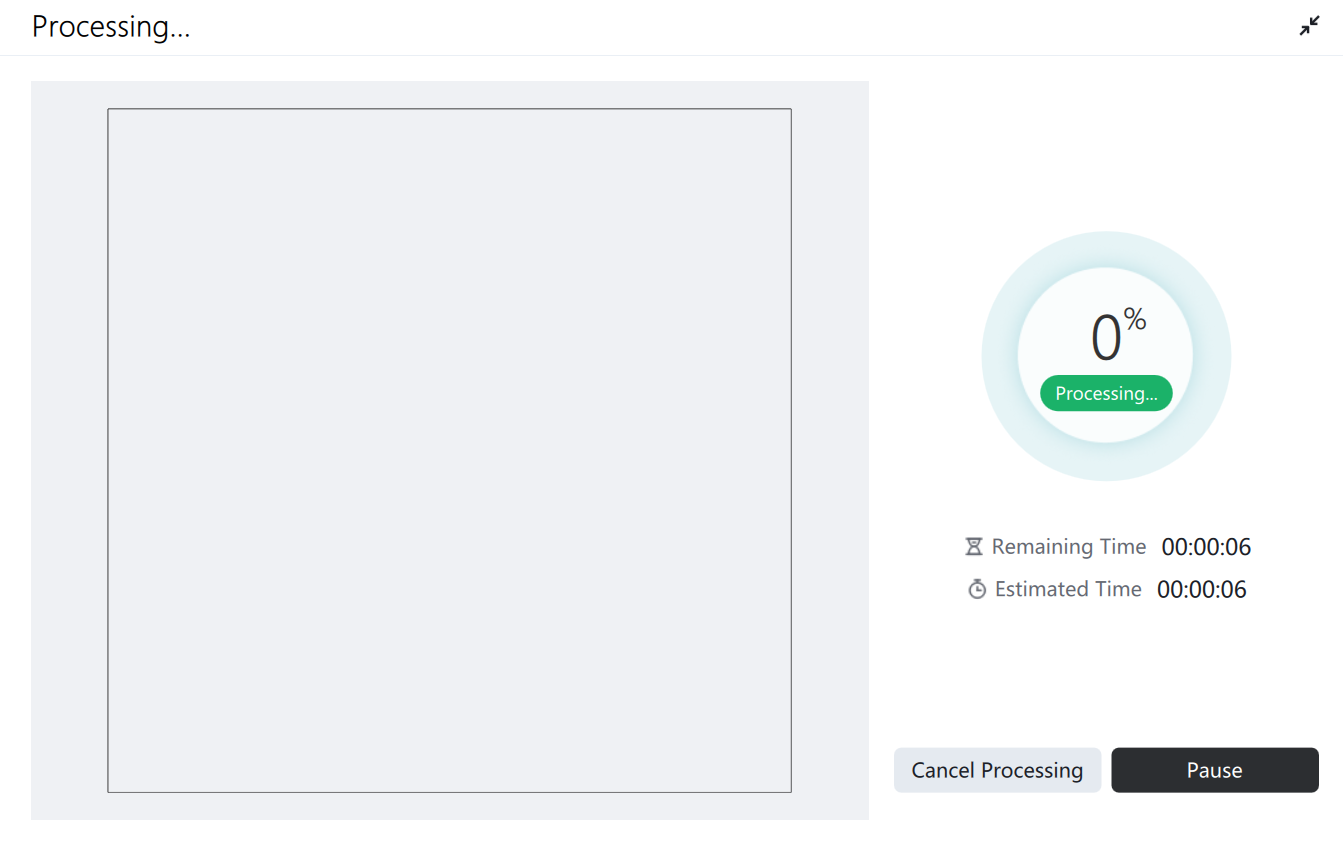
¶ Start processing
The "Processing in Progress" window allows you to view the processing progress and pause or cancel the process.
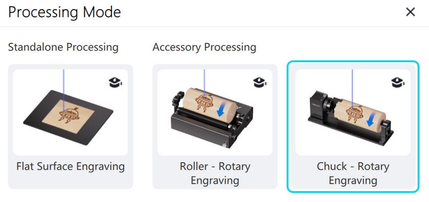
¶ Processing mode
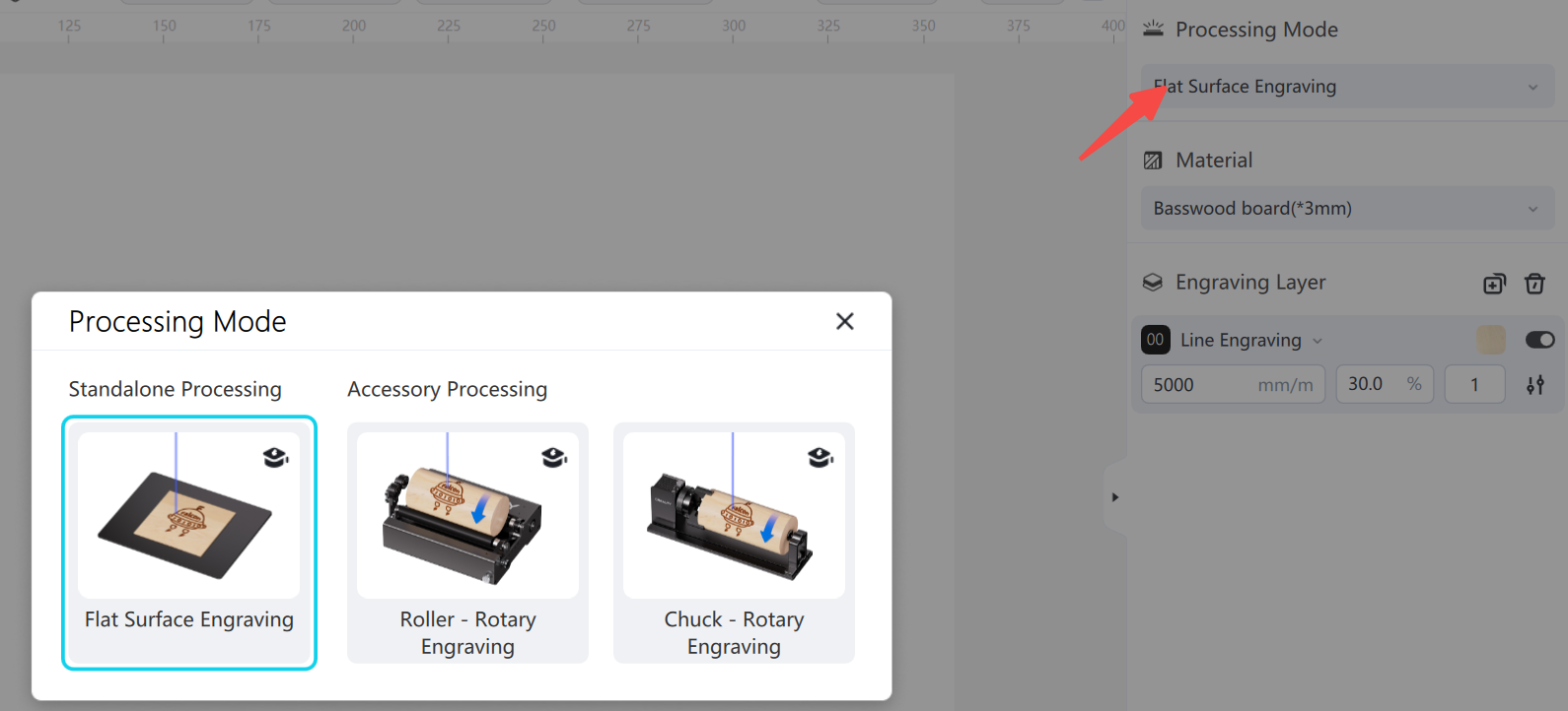
Function Description: Switches between different processing modes. Note that this function requires the use of rotating accessories.
Instructions for use:
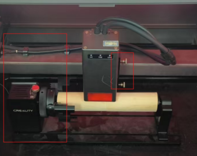
1.Install the rotating kit.
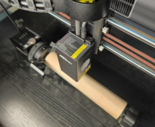
2.Align the rotating target below the laser, as shown in the figure.
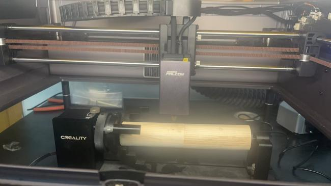
3.Choose rotary machining, and select chuck kit and roller kit according to actual needs.
4.The chuck kit requires you to input the diameter or circumference of the object to be sculpted (the roller does not require this input).
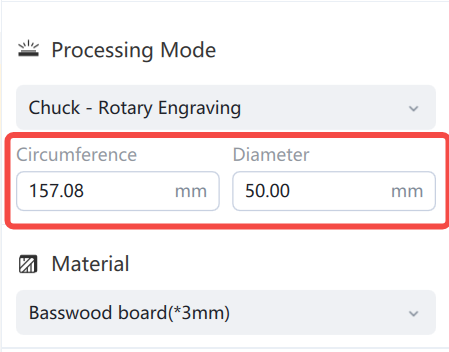
5.Draw the graphic, then proceed with the processing.
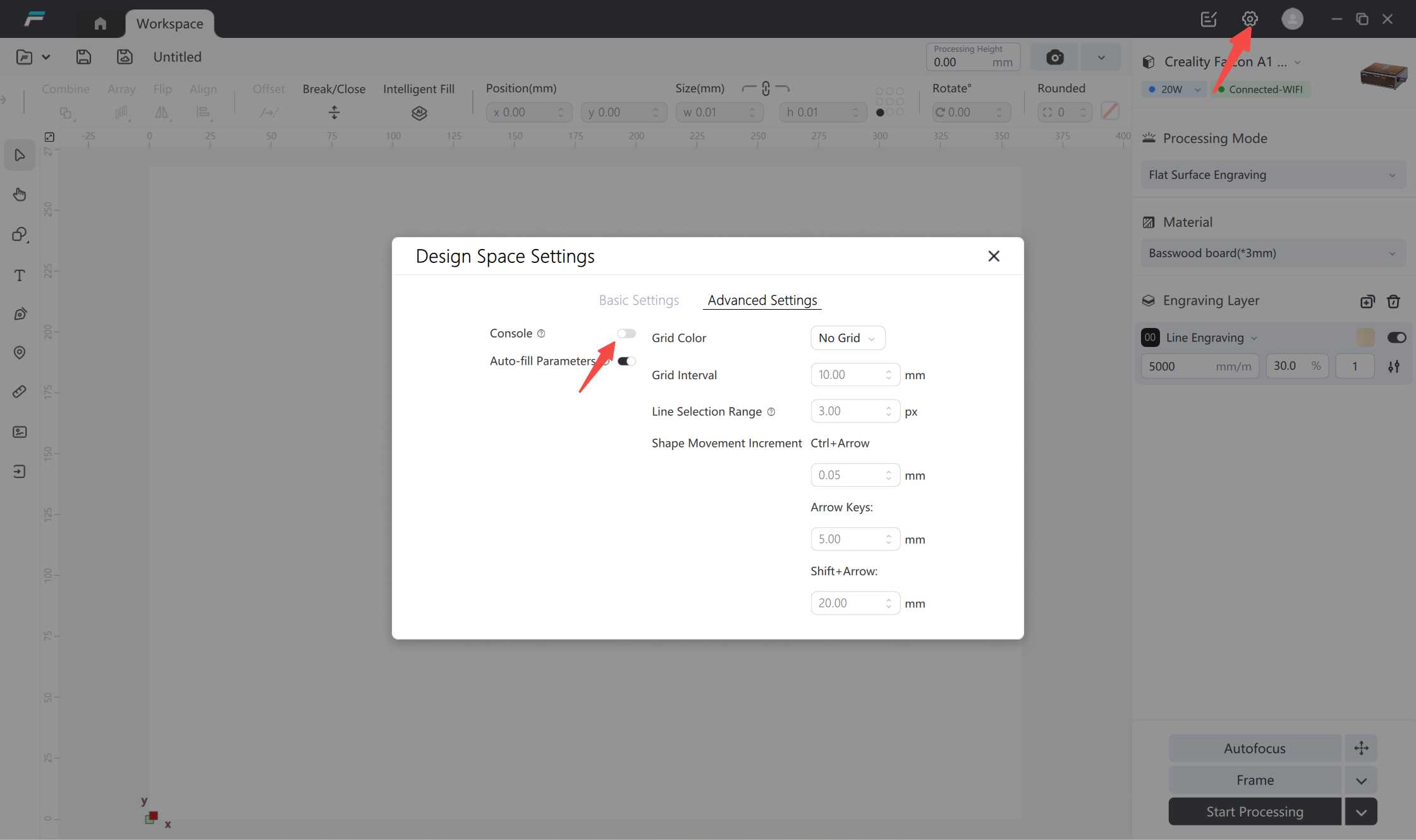
¶ Console
The console can be turned on or off in the advanced settings (A1PRO and T1 do not support console input).
Function Description:
- You can directly enter commands in the console window and view messages from the controller itself.
- You can enter commands in the text box, and after pressing Enter, the console will output the results.
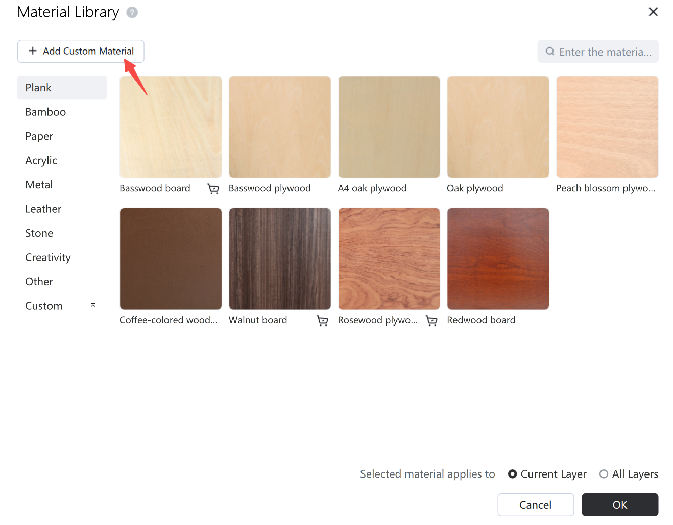
¶ Material parameter library
Functional Description:
- The material application method can be selected to apply to the current layer/all layers. After selecting the material, corresponding carving parameters are recommended based on the selected material, equipment power, and carving mode;
- All layers: Modify the default material in the system, and all current carving layers, newly added carving layers, and carving layers after adding new projects will be set to this material;
- Current layer: Only modify the currently selected carving layer material;
- Users can choose to print using the software's preset materials or new customized materials;
- Add custom materials
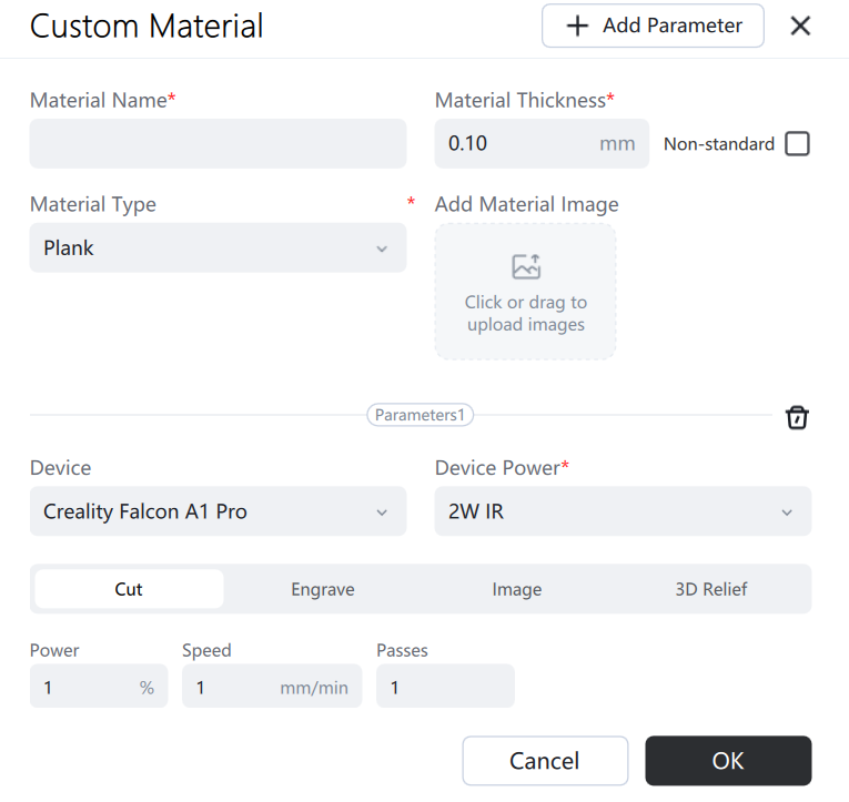
¶ QR code recognition material

Function Description:
After connecting the device to the camera, open the machine cover and place the material identification QR code under the camera. It will automatically read and identify the current material type. You can choose to apply it to all layers or the current layer (some devices do not support this function).
¶ Camera
¶ Photograph
Clicking the processing height input box will bring up the input boxes for shim height and material thickness.
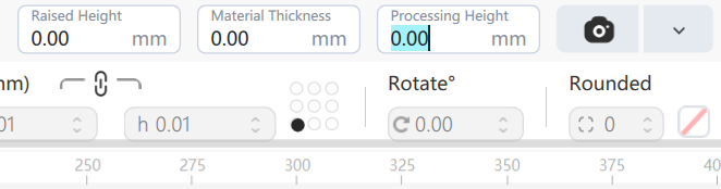
Function Description:
- Take a photo: Simply click the photo button to take a picture.
- Elevation Height: Enter the height between the base plate and the material. If a honeycomb panel is used, the thickness of the honeycomb panel must be entered.
- Material thickness: Enter the actual thickness of the carving material.
- Processing height: Input the sum of the shim height and the material thickness.
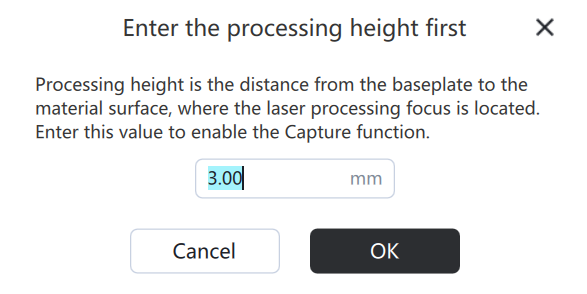
- Camera Positioning: After the camera is calibrated, the base image will be displayed on the canvas after taking a picture. Move the graphic to the object to be sculpted for processing (absolute position processing is required). If the material is moved, a new picture needs to be taken. The processing height must be correctly entered for each picture. If a different thickness of material is used...
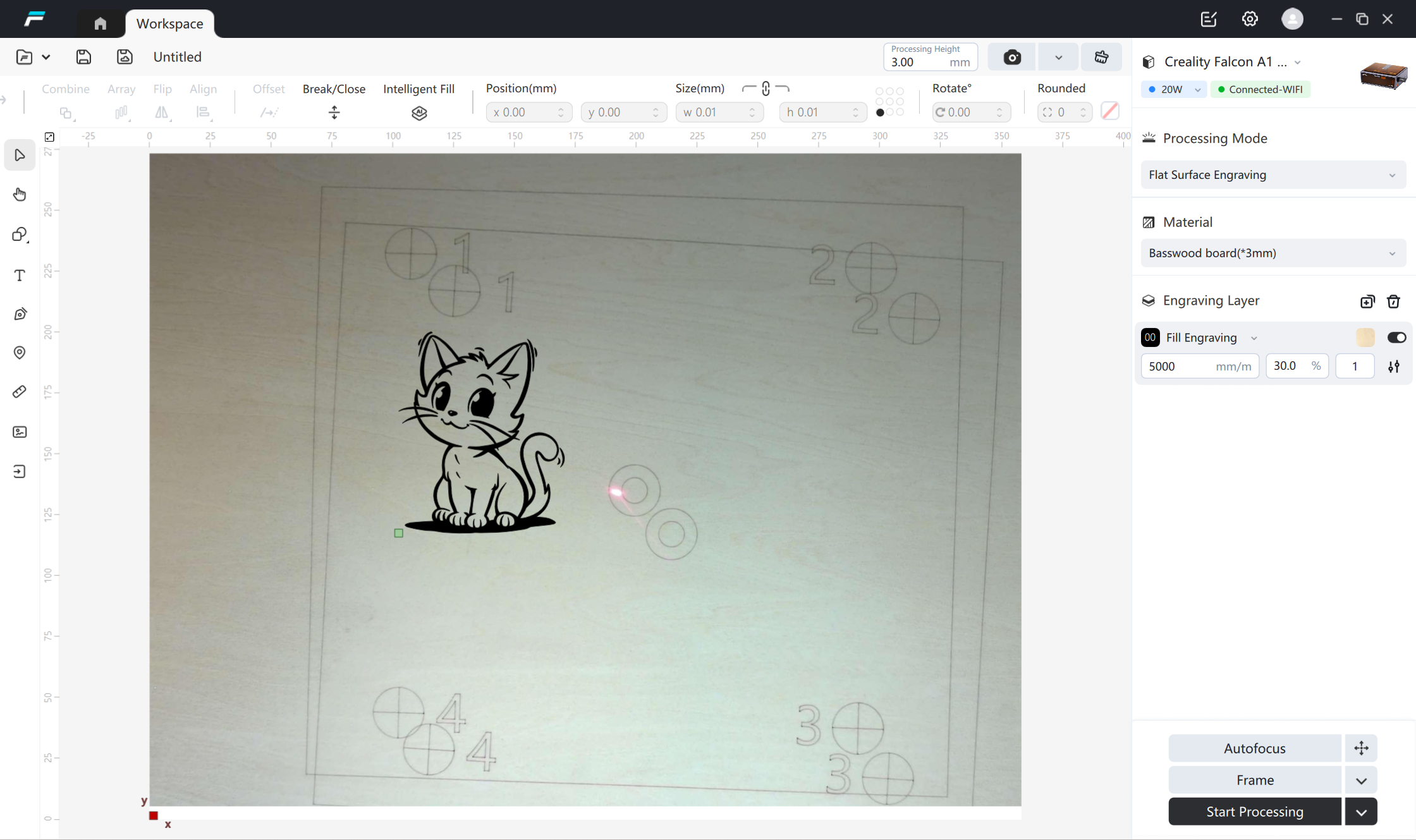
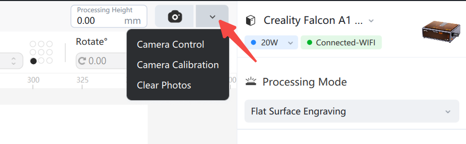
¶ Camera control
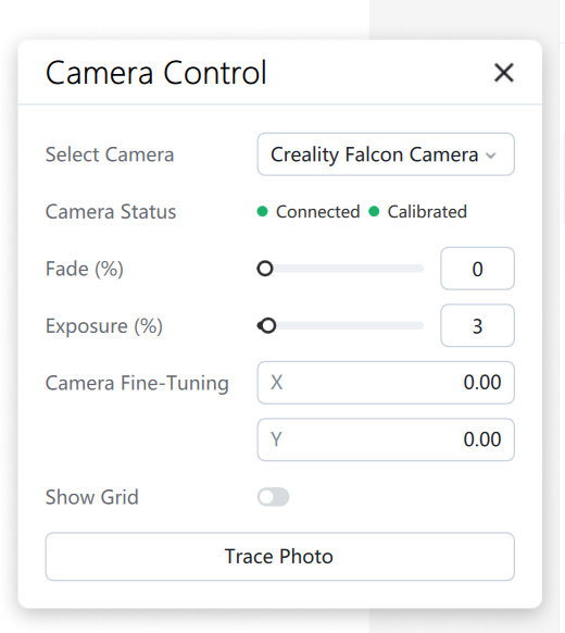
Function Description:
- Camera status: Disconnected, Connected, Uncalibrated, Calibrated .
- Connecting Cameras: The camera list displays the cameras currently connected to the device. Falcon cameras support automatic connection and can be disconnected by clicking the disconnect button or toggling the value to None.
- Camera fine-tuning : Move the captured image relative to its position on the canvas, make fine-tuning compensations, and move it along the X/Y axes.
- Show Grid : This toggle controls whether the grid is displayed on the canvas.
- Fade: Fades the display effect.
- Photo contour tracking: After taking a photo, the contour shape on the photo can be identified and extracted, just like image contour tracking;
¶ Camera calibration
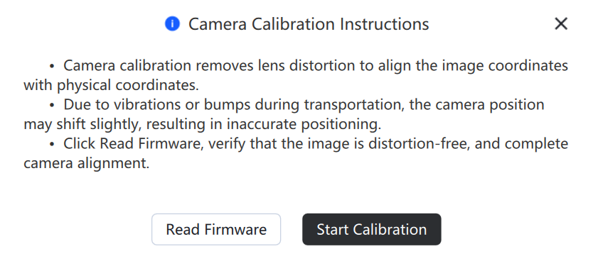
- Read firmware: Restores the camera calibration parameters to factory settings (this function is not available on some devices).
- Camera calibration: Go to the "Camera Calibration" page
- Camera calibration tutorial: https://wiki.creality.com/zh/laser-engraver/camera-calibration-guide
¶ Design Space Settings
¶ Basic
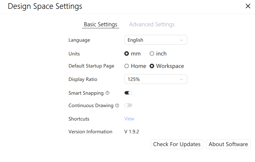
- Language: switch the software display language, default get system language to match with preset language, and display English if it can't match;
- Unit: switch the display unit, support mm and inch;
- Default start page: Next time you open the software, it will automatically go to the home/workbench page.
- Display ratio: Adjust the size of the displayed page
- Auto-snapping: when enabled, when drawing shapes with vector tools, the shapes can be closed automatically, and when dragging shapes, the shapes will be adsorbed to other shapes automatically.
- Continuous Drawing: When enabled, you can draw shapes or lines continuously, and automatically restore the selection state after drawing one shape or line when closed.
- Hotkey: Click the View button to display the “Shortcut Keys” pop-up window to see all the shortcut keys in the software.
- Version Information: Display the current version number of the software.
- Check for Updates: Check the current version of the software;
- About FDS: Click the “About Software” button to display the About Software pop-up window, in which the basic information of the software is displayed;
¶ Advanced
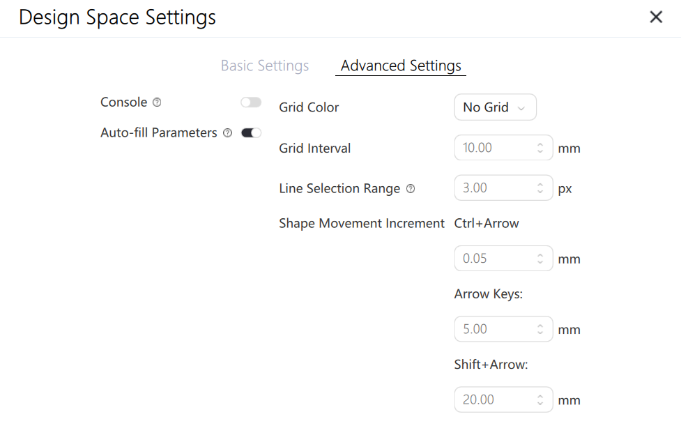
- Console: Displays the console window, where you can communicate directly with settings via the GRBL protocol;
- Automatic parameter filling : When enabled, it changes the recommended parameters for automatic material filling at different power levels; when disabled, it disables automatic parameter filling.
- Grid color: Sets the color of the lines in the canvas, which can be switched between light gray, dark gray, black, and no grid.
- Grid Spacing: Adjusts the grid spacing in the canvas; the default is 10mm.
- Line selection range: Adjust the effective range of the selection objects. Increasing the value will make it easier to select unclosed line graphics.
- Shape movement increment: Sets the movement distance when moving using Ctrl+arrow, arrow, and Shift+arrow respectively.
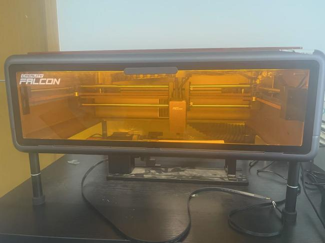
¶ 4. External Rotary Kit Wiring Instructions
¶ Falcon2 pro
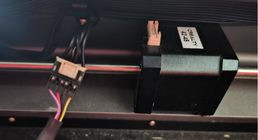
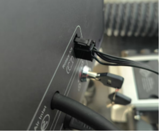
1.Disconnect the original Y-axis connection (the middle of the front fill light strip), and then connect it to the rotation kit cable.
2.Remove the isolation layer at the bottom and place the rotating kit in the center. Then adjust the height of the laser head from the engraving target (such as a log) by turning the screw on the right side of the laser module to avoid collision with it.
3.Then close the mask and the wiring is completed.
¶ Falcon A1
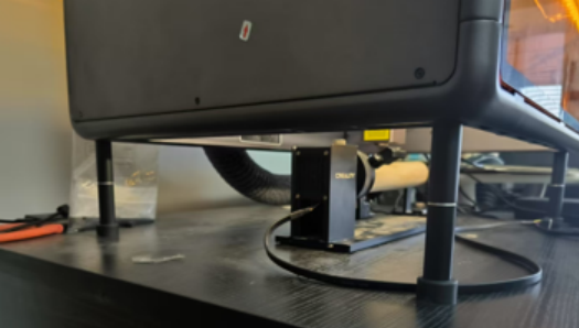
1.First, install the heightening supports at the four corners of A1.

2.Remove the bottom plate of Falcon A1 and place the swivel assembly in the center.
3.Connect one end of the A1 dedicated Rotary Kit adapter cable to the Rotary Kit cable, and the other end to the "Rotary Kit" port on the A1 device.
4.Adjust the height of the laser head from the engraving target (such as a log) by turning the screw on the right side of the laser module to avoid collision with it.
5.Then close the side cover and top cover, and the wiring is completed.