¶ 1. Phenomenon Description
The machine starts engraving, but there are no engraving marks on the material. Only the red indicator light on the laser module is lit.

¶ 2. Cause Analysis
Laser module cable is damaged
The laser module is damaged and does not emit light
Mainboard control module port wiring is damaged
¶ Troubleshooting
1. If you don't have a multimeter, you need to replace the laser module and its cable.
2. If you have a multimeter, you can test it in the following steps:
① Set the engraving file parameters to 100% power, export the G-code file to a TF card or prepare for online engraving;
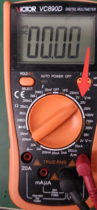
② Set the multimeter to "DC voltage" or "DC voltage 20V" range;
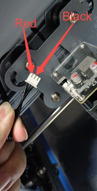
③ Unplug the wiring on top of the laser module, prepare the engraving file;
④ Connect the test probes as shown in the image below.
¶ Pin Description:
Test PWM+GND pin output voltage is 3V/5V
GND+VCC pin output voltage is 24V
| PWM | Signal Pin |
| GND | Ground/Negative Pin |
| VCC | Positive Pin |
When running engraving through TF card or online connection, use a multimeter to measure the voltage between PWM pin (red probe) and GND pin (black probe).
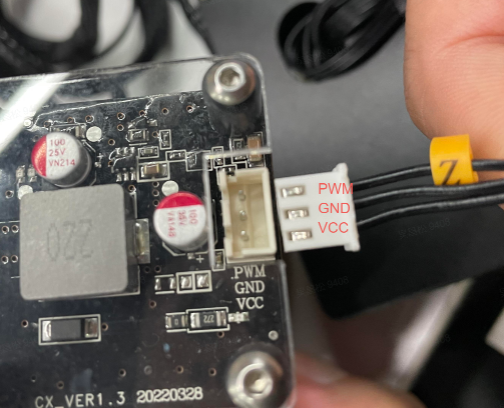
If the measured voltage is around 3V/5V, the laser module is faulty, please replace the laser module;
If the measured voltage is not around 3V/5V, it means the laser module cable is faulty, please replace the laser module cable.
¶ Friendly reminder
If you still haven't resolved the issue after following the steps in this document, or if you encounter any difficulties during the process, you can click the right corner of the wiki page online support to contact our after-sales team for more help.