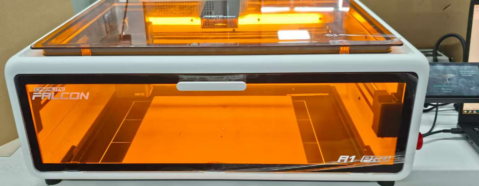
¶ Falcon Design Space Camera Calibration Creality Falcon A1 Pro
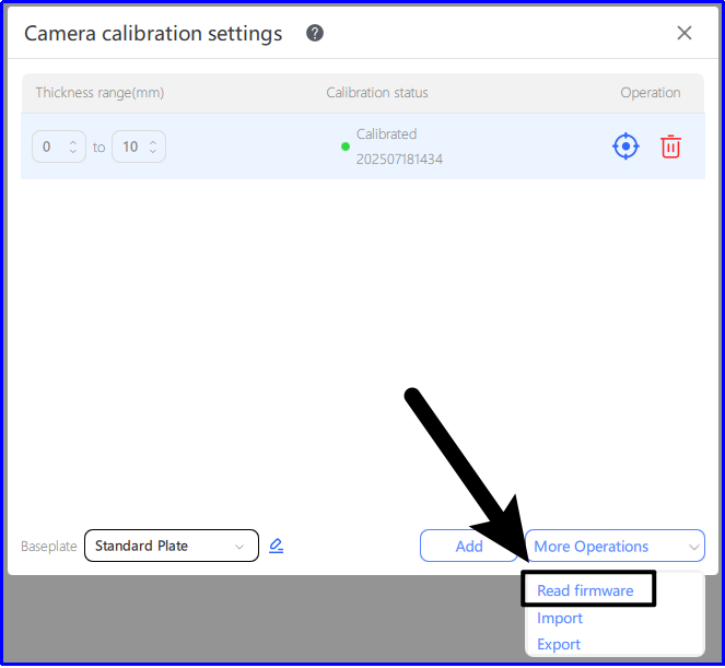
If you are using it for the first time, you are advised to use the camera parameters directly by [Read firmware];

matters need attention :
Ambient light: Ensure that the calibration is performed when the light is sufficient and the LED is on during the day, and avoid calibration at night when the light is weak.
Base plate: If the workbench contains a large number of similar circular structures (such as honeycomb panels) or is seriously reflective, it is recommended to cover the working area with large sheet materials (A4 paper, linden plywood, etc.) before calibration.
Camera calibration: If your machine can [Read firmware], it is recommended to skip this step directly: ensure that the surface of the calibration card is clean, the calibration card is flat and no lifting, the more flat the calibration card is, the better the camera calibration effect will be.
Camera alignment: When coordinate points, make sure that the thickness of the material is consistent with the actual thickness of the carved material.
Camera displacement: If the camera position changes, the camera needs to be aligned again.
Material thickness change: If the material thickness changes significantly (more than 3mm), the camera needs to be aligned again.
How to connect the device to the camera:
Use a USB cable to plug the TYPE-C port into the Creality Falcon A1 Pro port
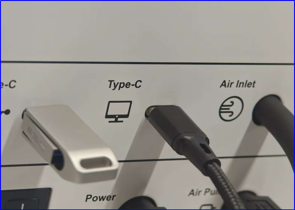
The software will automatically connect the device to the Creality Falcon Camera for camera calibration interface.

If it cannot be connected properly: Determine whether the USB Type-C port is inserted into the computer port of the device.
Falcon Design Space version is higher than V1.7.7 (including V1.7.7).
¶ Camera calibration operation:
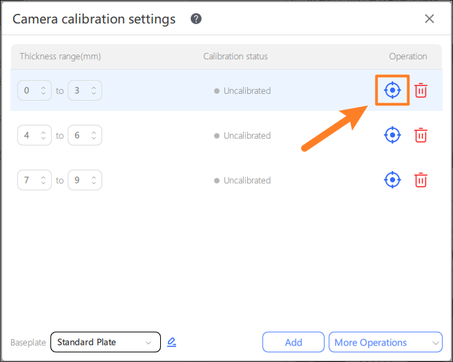
Different thicknesses and different base plates can be set:
①. The camera calibration parameters can be saved for different baseplates with varying heights. Please ensure to switch the 【Baseplate】 option after replacing the baseplate.
②. It is recommended to add a range calibration once for the thickness of 1-3mm. The system can automatically adapt the camera calibration parameters corresponding to the selected thickness in the material library. When the selected material thickness is not within the range or non-standard, the system will apply the first thickness range calibration parameter by default;
③. If the camera position does not change, only the material height changes, you can skip the camera calibration step and directly carry out the camera alignment.
④. You can select [Read firmware] in [More operations] to obtain the default parameters calibrated at factory and use them directly.
¶ Camera calibration operation:
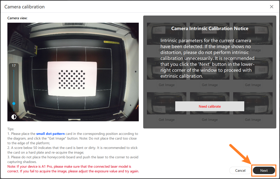
Place the calibration card in the indicated position and click to obtain the image:
①. Calibrate in the form of a nine-grid, and move the position of the calibration card according to the software schematic diagram each time.
②. If the image acquisition fails during calibration, the calibration card can be moved to the center position by 1~3mm each time.
③. Pay attention to the moving laser module during calibration to avoid blocking the calibration card.
④. You can adjust the brightness of the image through the [Exposure Bar] on the right. If the calibration score is too low, you can adjust this setting.
⑤. For captured images, a score of ≥50 is recommended for the best results; scores >1 are usable but with slightly lower quality.

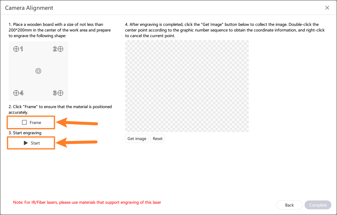
¶ Camera alignment:
①. Place the material larger than 250x250 (the standard linden board from the factory) at the center of the carving, and close the protective cover
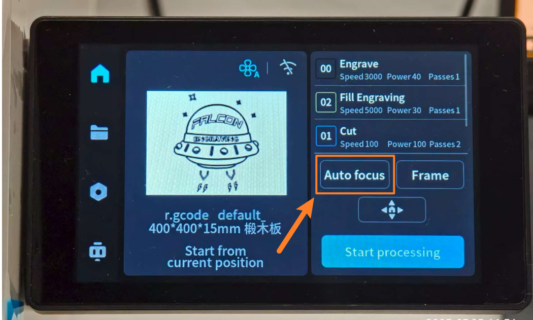
②. Select any file on the screen for autofocus
③. After completing the first two steps, click [Frame] to determine the carving range and click [Start] to start carving.
④. Click [Get image] to obtain the carved calibration image
Double-click the center point of 1, 2, 3 and 4 corresponding to the calibration pattern in sequence, and click [Complete] to complete the camera alignment.
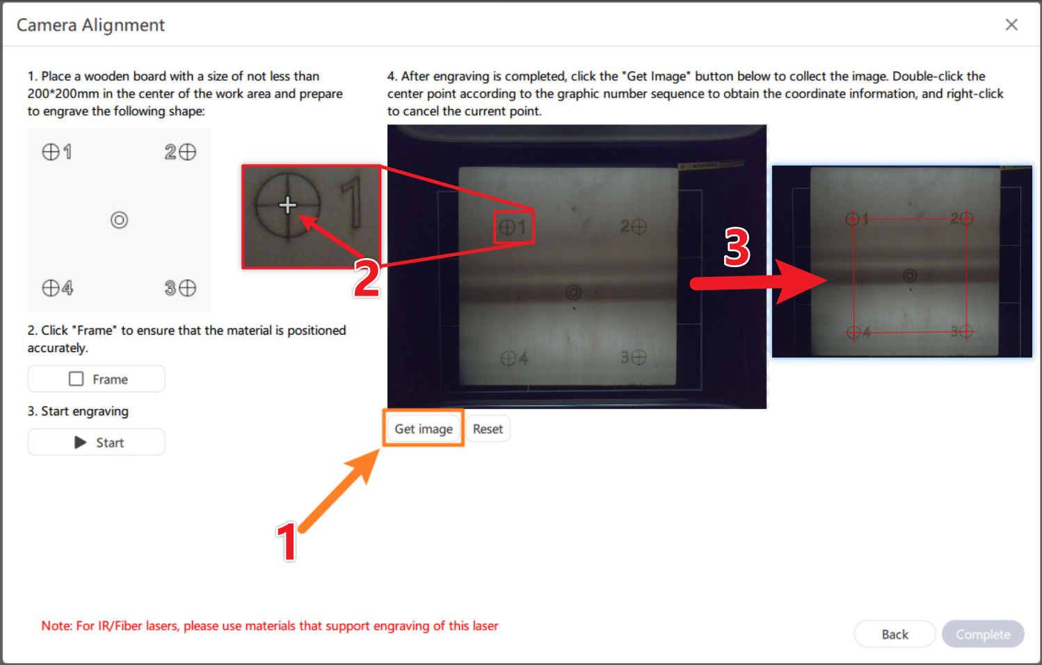
The wheel is enlarged. Long press can drag it, and double click will show a red mark. If the double click position is wrong, you can [Reset] and double click again;
¶ abnormal condition :
If the double click point is located outside the center of the calibration pattern, the overlay will not be acquired during the photo.
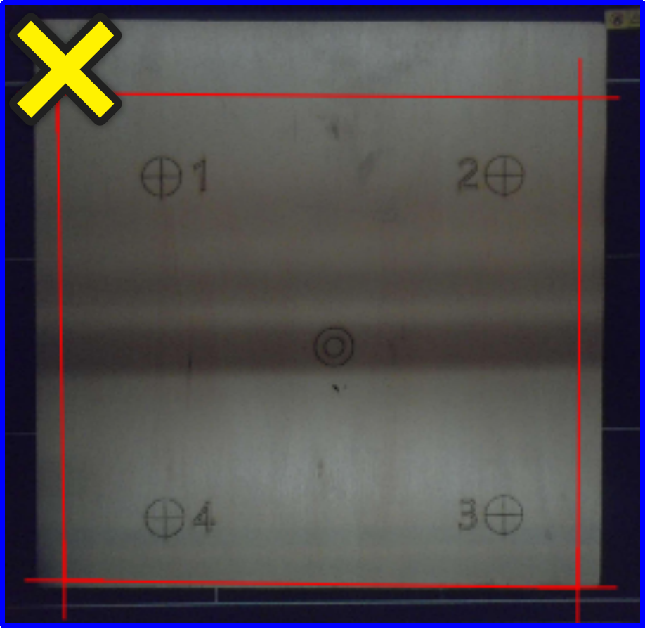

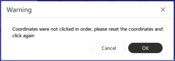
If you do not double-click the center of the calibration pattern in order 1-4, an error message will be displayed indicating that the click was not in order.

¶ The photo location is not accurate? Please fine-tune the camera
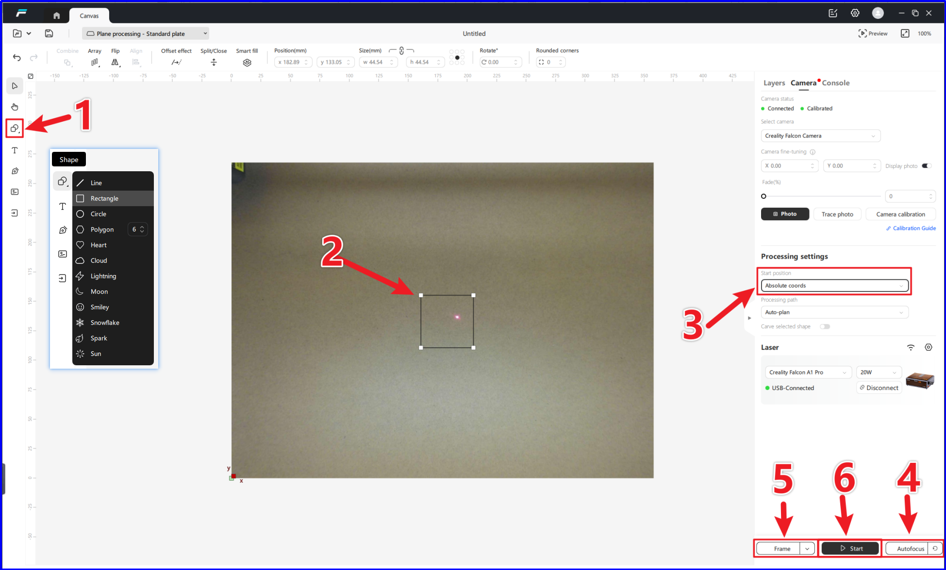
Carving test patterns for camera fine-tuning:
Select the [Shape] tool and draw a rectangle
Draw a rectangle in the center of the canvas for camera calibration and fine-tuning tests
Select [Absolute coords] or the carving will be meaningless
Click [AutoFocus] and wait for the device to complete autofocus to ensure correct focus
Go to the frame preview and click [Frame] to make sure the carving position is on the carving material
[Start] Start carving the test pattern
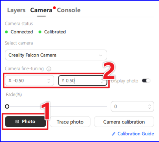
2.After carving, click [Photo] to get the carved image for fine-tuning and calibration.
If the camera is not perfectly positioned, the carved image will appear in shadow.
If you need to make fine adjustments to the camera, make fine adjustments until the images fully overlap.
The left figure shows the uncalibrated carving pattern, and the right figure shows the uncalibrated pattern:

At this point, the fine-tuning work has been completed. Finally, the board is removed, the carving of the same thickness is placed and photographed again, and the image is directly placed in the desired position for carving.