¶ Falcon Design Space Camera Calibration Guide
¶ Why do cameras need to be calibrated?
Camera positioning essentially involves using image pixels to deduce the real-world physical location; calibration corrects lens distortion, determines pixel scale, and aligns the camera's orientation. Without calibration, pixel coordinates are virtual and cannot be converted to real-world positions, rendering positioning completely unusable.
¶ The principle of camera calibration and alignment
- Calibration: Corrects lens distortion, calculates the camera's internal imaging ratio (intrinsic parameters), and straightens distorted images;
- Alignment: Calculates the camera's position and orientation relative to the real world (extrinsic parameters), and aligns the camera coordinate system with the world coordinate system;
- Uncalibrated: The image is distorted or out of proportion.
- Misalignment: The camera's location is unknown, and the overall positioning coordinates are off-target.
- Only with calibration and alignment can the actual physical location be accurately calculated from the image pixels, thus enabling camera positioning.
¶ 1. Preparation for Camera Calibration
Calibration Instructions:
Falcon Design Space Version must be higher than or equal to V1. 9 . 0.
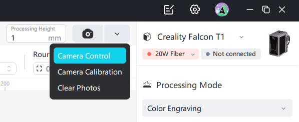
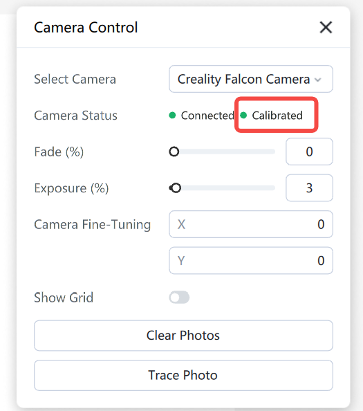
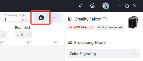
The whole machine device , when connected to the software for the first time, can automatically read the camera parameters pre-installed in the machine at the factory, open [Camera Control] to view the calibration status , and click [Take Photo] in the calibrated state to directly perform photo-taking and positioning.
Assembly equipment requires self-performed camera calibration. Refer toPoint 3 of the Tutorial, "Camera Calibration Operation".
After the carving is completed, if the camera positioning deviation is found to be large, please refer to the following steps to calibrate the camera.
Precautions:
1. Ambient light is sufficient : Ensure calibration is performed during the day when light is sufficient, avoiding low light at night ;
2. Baseplate Purity : If the baseplate is a honeycomb panel, mottled or highly reflective, before calibration please use solid-colored cardboard or wood to cover the working area ;
3. Calibration card flatness: Ensure that the surface of the calibration card is clean, flat without warping. The flatter the calibration card, the better the camera calibration effect;
4. Camera displacement: If the camera position changes, it is necessary to perform camera alignment .
Prepare for calibration:
1. Connect the camera
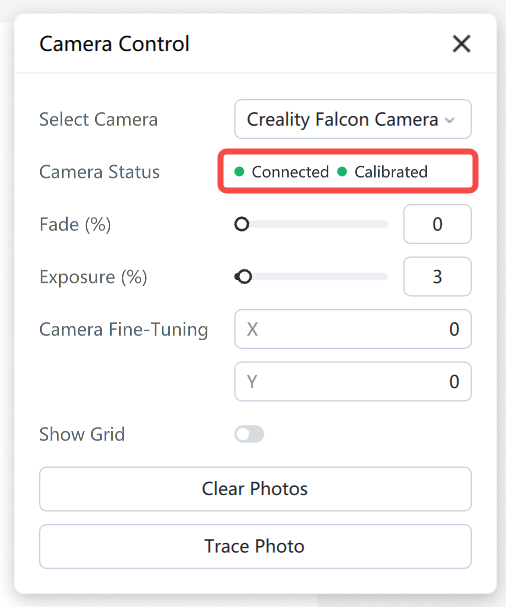
After the whole machine device is connected, the software will automatically connect to the device and Creality Falcon Camera, and you can enter [Camera Control] to view the camera connection status .
When assembling the device, an additional USB cable is required to separately connect the device camera to the computer.
2. Start calibration
Open the camera calibration pop-up window,click [Start Calibration]
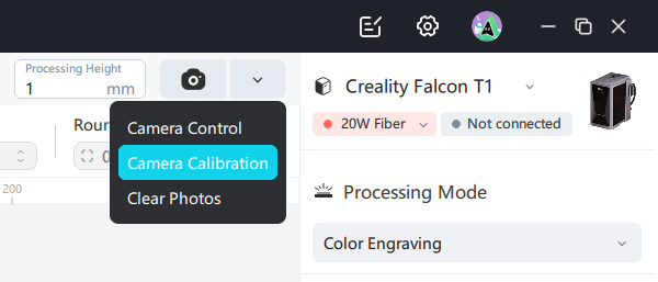
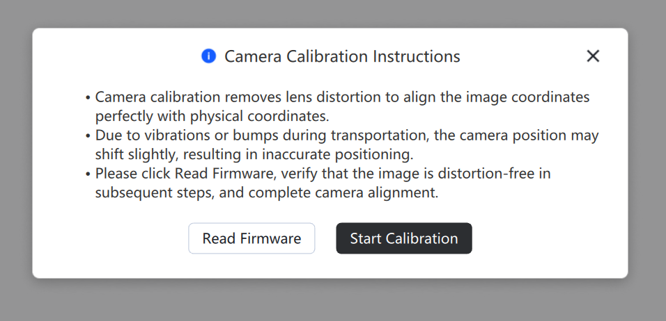
If self-calibration of the whole device does not yield satisfactory results, you can click [Read Firmware] to restore the factory camera parameters
3. Calibration Verification
Click [Take Photo] to check if there is any obvious distortion in the photo corner
Left side example is a case of severe deformation , and a grid paper can be placed on the bottom plate without silk screen for observation
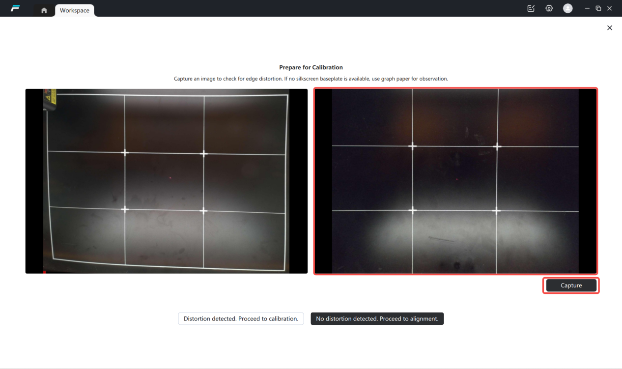
If there is no serious deformation, click [to align], see point 2 of the tutorial , "camera alignment operation"
If the deformation is severe, click [Go to Calibration] to view the third point of the tutorial , "Camera Calibration Operation"
Function Description:
Camera calibration includes two steps: calibrating internal parameters and aligning external parameters.
The function of calibrating internal parameters is to correct image distortion, and it is generally applicable to the initial calibration of an uncalibrated machine or the recalibration after camera displacement.
The function of aligning external parameters is to achieve self-adaptation for positioning materials of different heights, generally applicable to improving camera positioning accuracy.
Under normal circumstances, the whole machine equipment does not need to calibrate the internal parameters and can directly perform external parameter alignment. Only in abnormal situations where the image distortion is very large is it necessary to calibrate the internal parameters.
¶ 2. Camera Alignment Operation
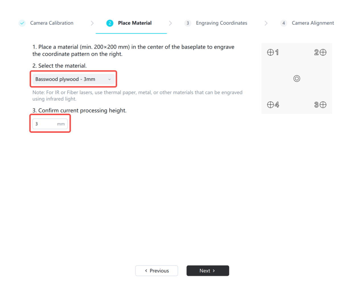
1. Place the materials
①Place consumables larger than 250x250 in the engraving center and close the protective cover(Place basswood board or coherent paper according to the light source)
②Select the material, enter the processing height, and click [Next]
Note: The processing height is the height from the base plateto the surface of the material. If a honeycomb panel is placed, the processing height is the thickness of the honeycomb panel + the thickness of the material; if no honeycomb panel is placed, the processing height is the thickness of the material.
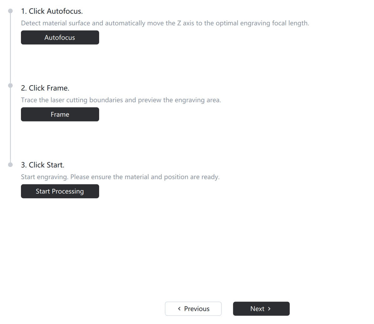
2. Carving Coordinates
Click [Auto Focus], after focusing is completed, click [Trace Border], confirm the engraving position on the material, after completion, click [Start Processing], and after processing is completed, do notremovethe material,directlyclick [Next Step]
Note: Need to close the cover and stop function in the equipment settings , in order to open the protective cover to view the border range , adjust the position of the engraving material , please close the protective cover when engraving.
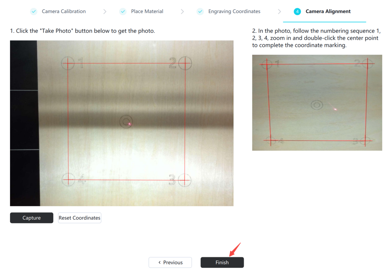
3. Align the camera
①Click [Take Photo] to obtain thecoordinate photo
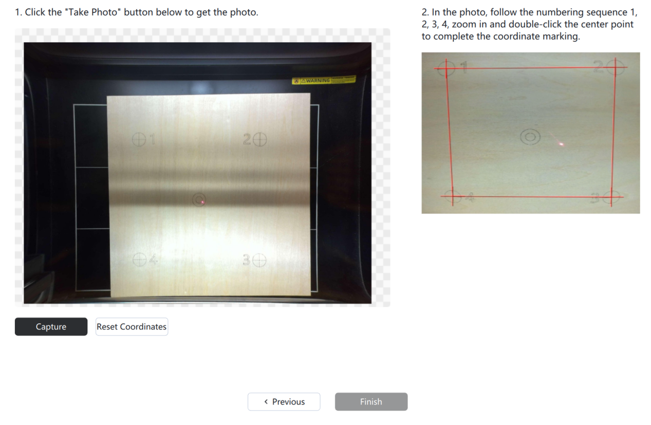
②Zoom in on the photo, find thenumber 1 graphic, double-click on the center point to show a red cross marker
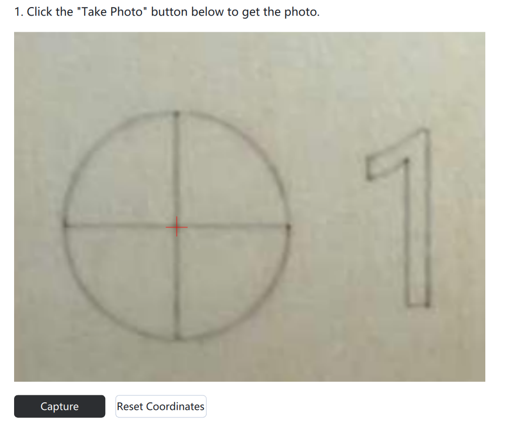
Note: The mouse wheel can zoom the photo , hold down the left button to drag the photo; if the double-click position is incorrect, click [Reset] to clear the markers
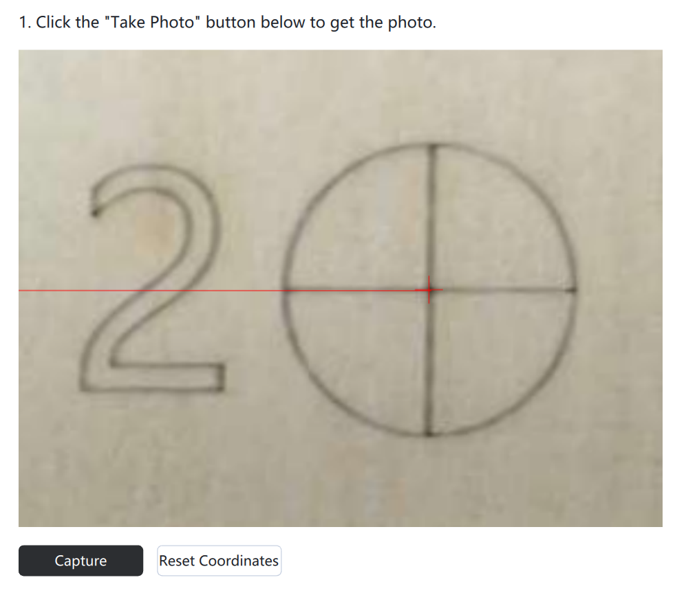
② After completing number 1, enlarge the figure of number 2 and double-click the center point, then a red line segment will appear
③Double-click the center points of the calibration patterns corresponding to 3 and 4 in sequence, then click 【Finish】 to complete camera alignment.
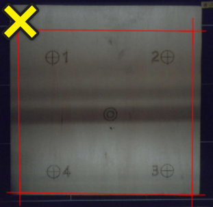
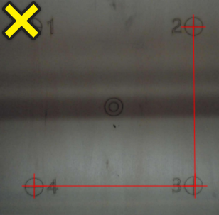
Example of incorrect operation:
The position of the double click is outside the center of the calibration pattern.
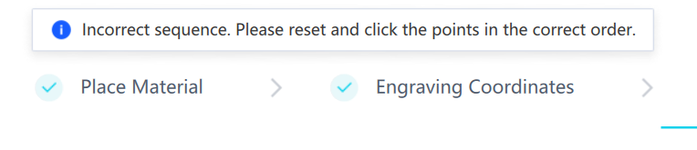
Error message appears because the center of the calibration pattern was not double-clicked in the order of 1-4.
¶ 3. Camera Calibration Operation
If you don't have a camera calibration card, you can click on the blue title to download and print it.

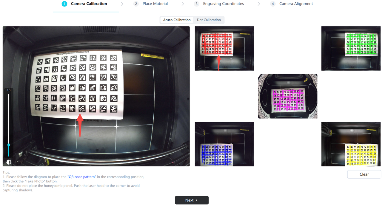
¶ Method 1: Calibration using Aruco calibration card
Select Aruco calibration. Large-format devices need to take a five-grid photo, while small-format devices only need to take a centered photo.
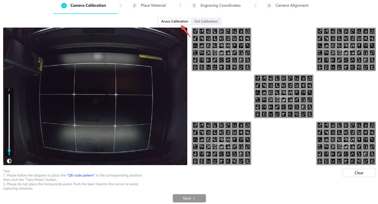
① Push the laser module to the upper left corner, and place the calibration card in the central area of the baseplate
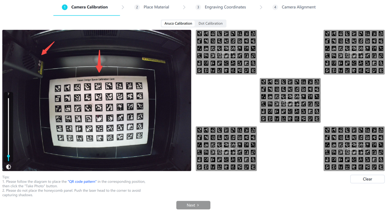
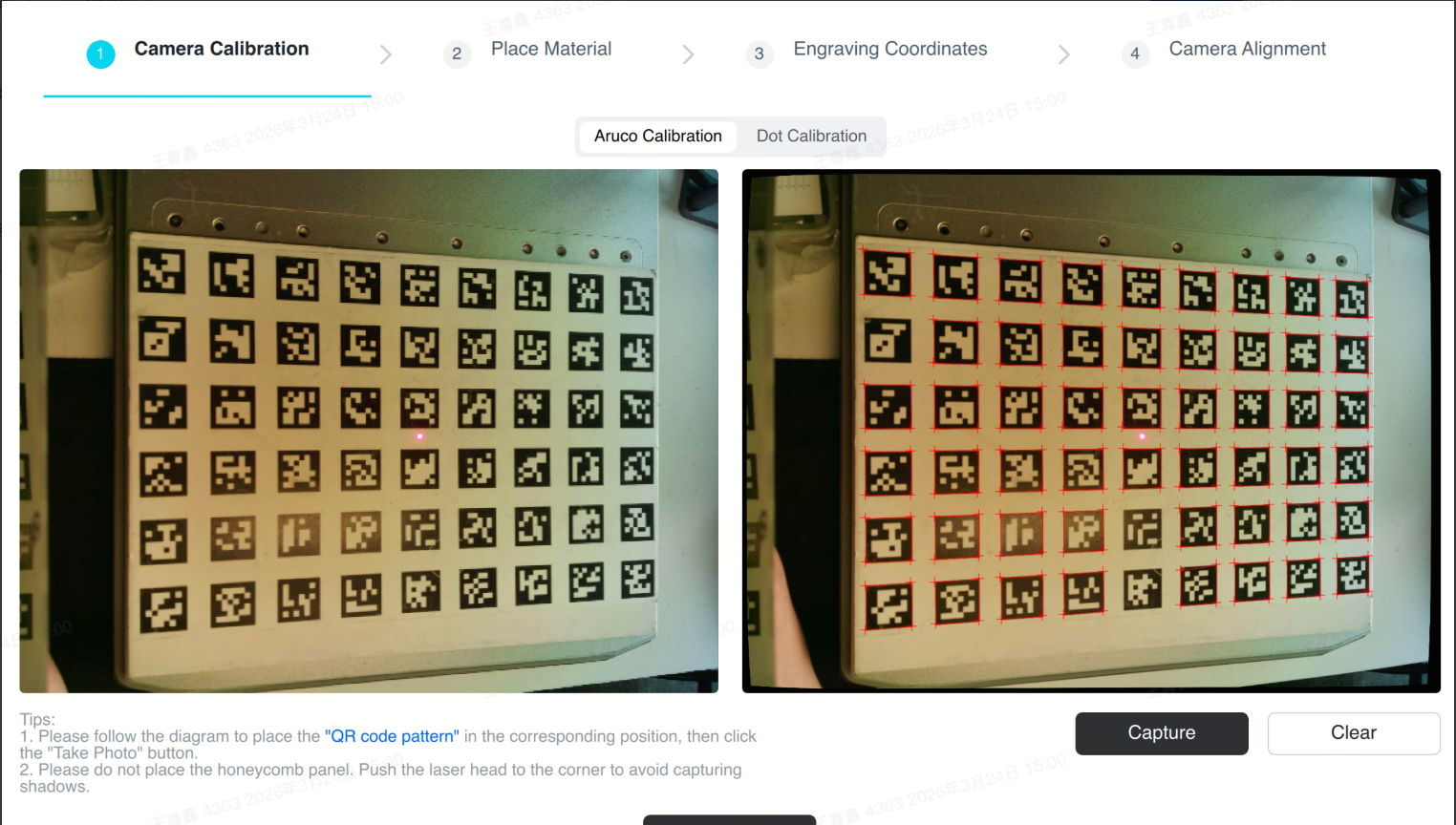
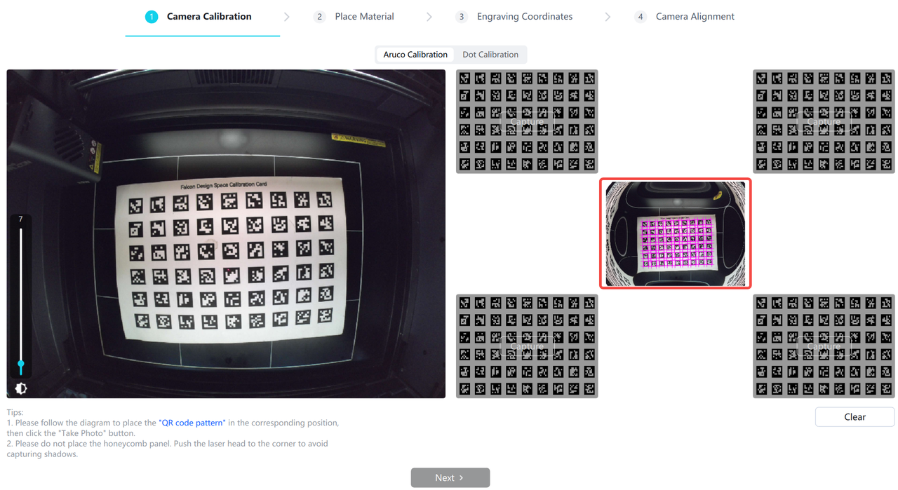
② Click [Take Photo] in the center grid to capture an image
③ Place the calibration card below , click [Take Photo] to capture an image
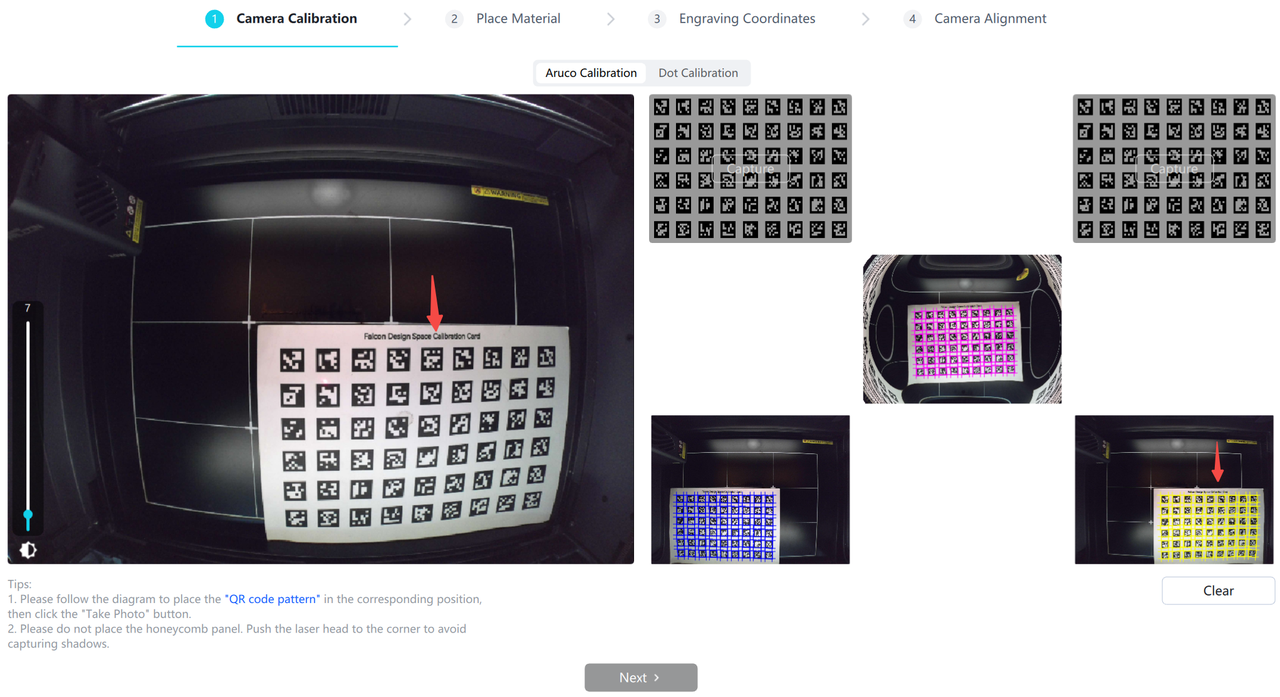
④ Move the laser module to the lower left corner and place the calibration card above it to prevent the laser module from blocking the calibration card
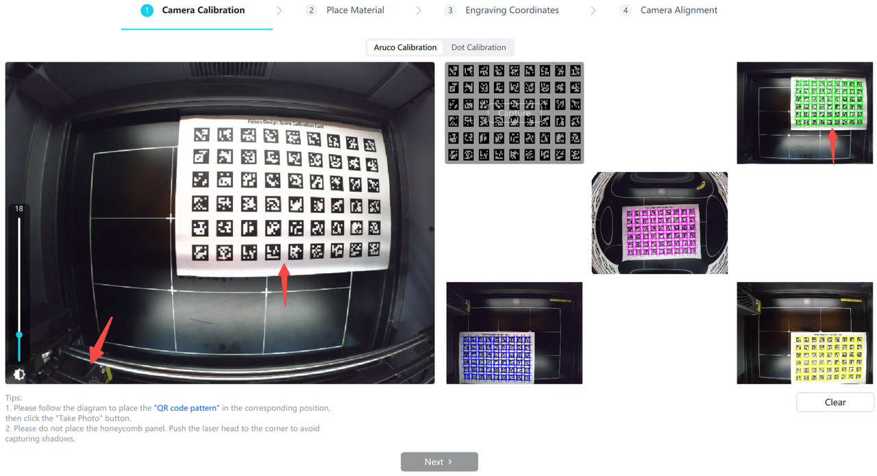
⑤ After obtaining the photos of all positions, click [Next] to enter the alignment operation, and check the second point, "Camera Alignment Operation"
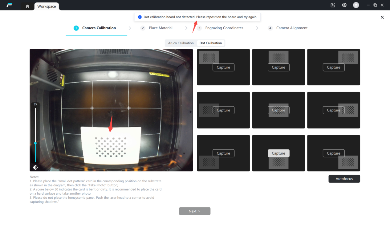
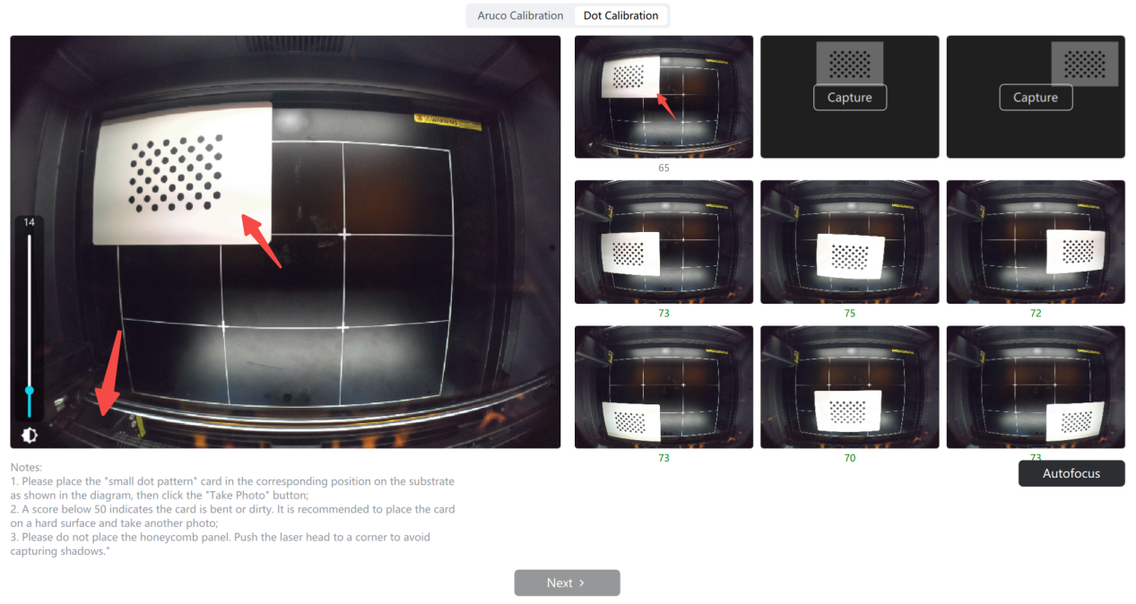
¶ Method 2 : Calibration using a dot calibration card
Select small dot calibration
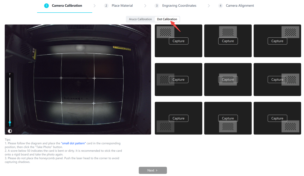
① Push the laser module to the upper left corner, and place the calibration card in the central area of the base plate
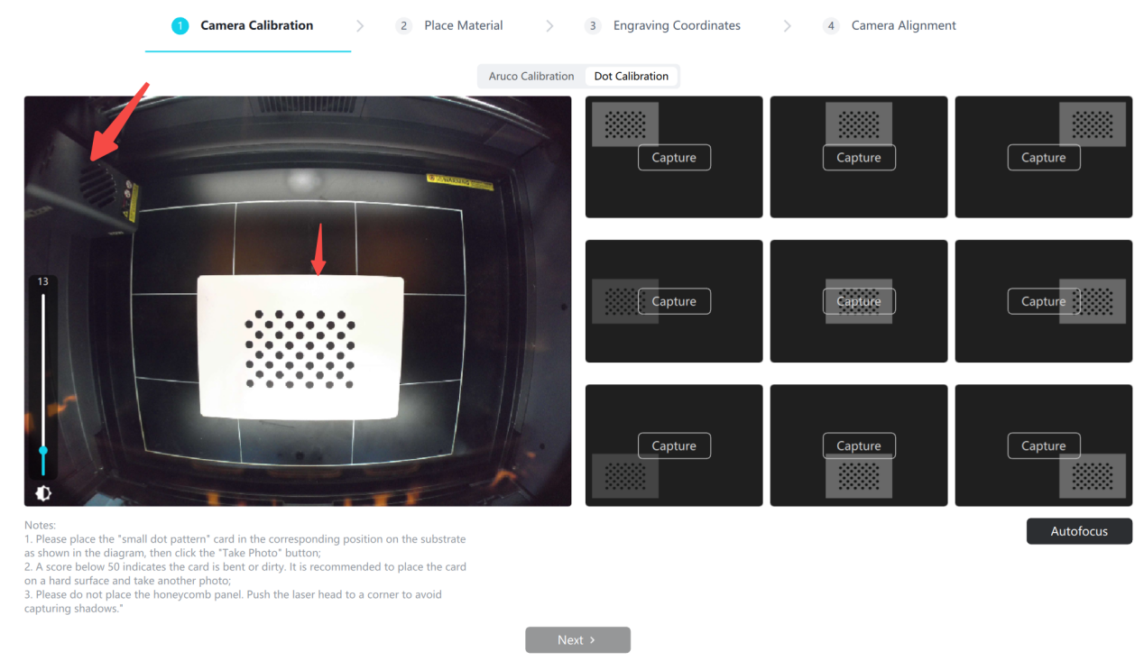
② Click [Take Photo] in the center grid to capture an image
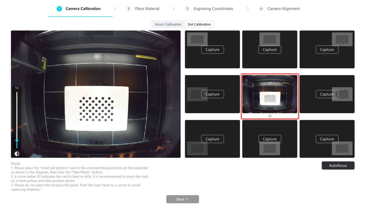
③ Then place the calibration card at other indicated positions respectively, and click to acquire the image , the calibration card can be placed along the edge
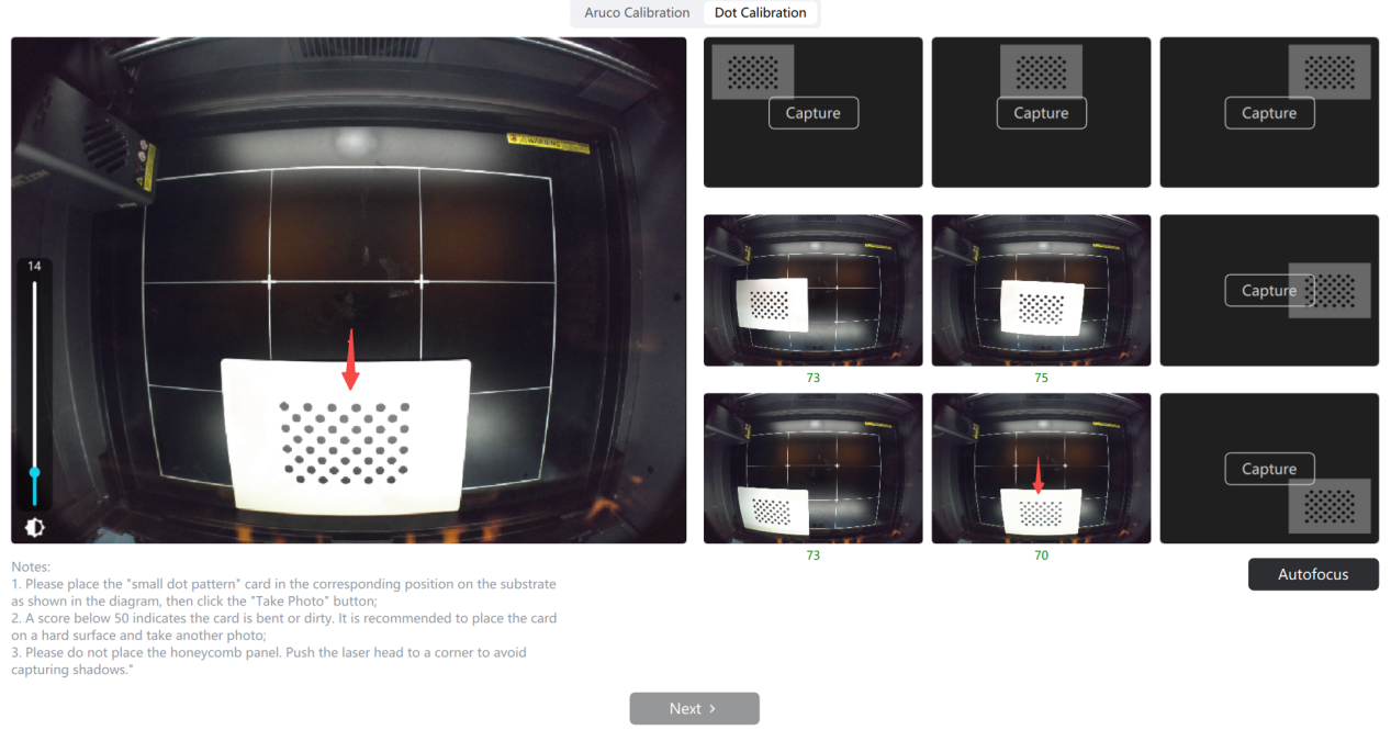
④ After obtaining images from all 9 positions, click [Next] to proceed to the alignment operation; refer to the second point of the tutorial, "Camera Alignment Operation".
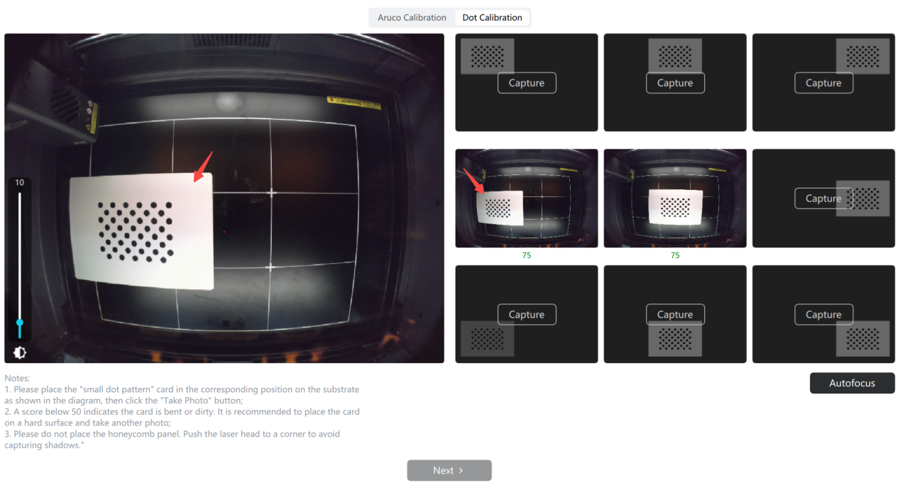
Abnormal Situation:
①Ambientlightis too bright, causing reflections in the photo
Photo reflection causesimage acquisition failure, you can try the following methods:
1) Adjust the left blue exposure bar (supported on some devices), and re-acquire the image
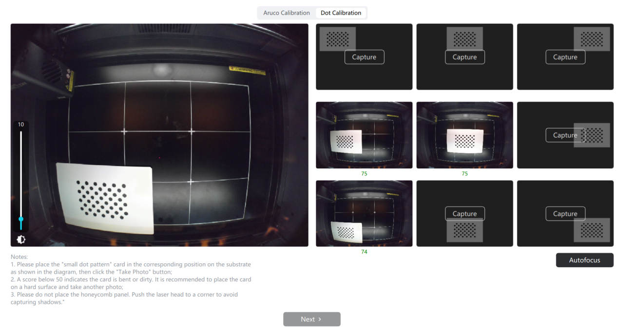
2) Move the calibration card to avoid the reflective area and re-acquire the image
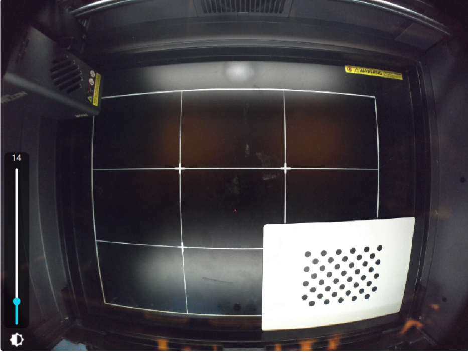
Before moving:
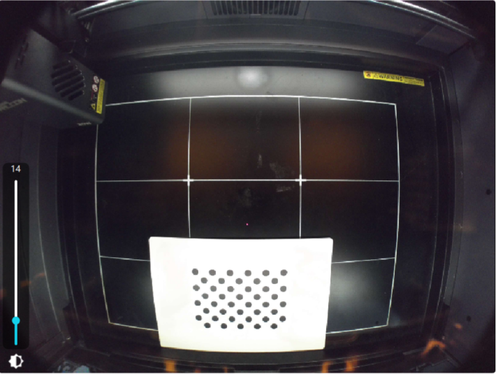
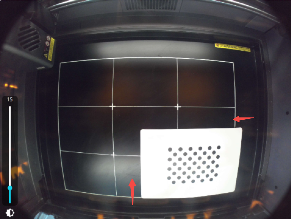
After moving:
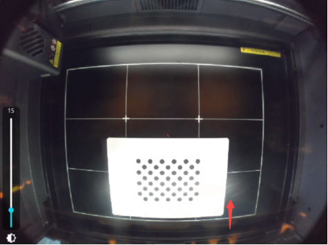
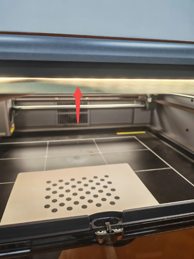
3) Use an object to block the light strip above and re-acquire the image
②Photo score is too low
The score of the photographed image is recommended to exceed ≥50 for the best effect, and a score >1 can be used but with slightly inferior results.
Low score can move the calibration card slightly towards the center , and then acquire the image again
Before moving:
After moving:
③Shadow occlusion photo
When taking the upper photo, move the laser module to the lower left corner to prevent it from blocking the calibration card, as there are shadow areas on the calibration card which will affect the recognition effect . The same applies when taking the lower photo
¶ 4. Slight deviation in the photo-taking position ? Please make fine adjustments to the camera
How to perform fine-tuning?
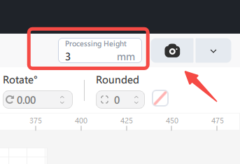
1. After calibration, enter the correct machining height, click [ Take Photo ] , and the photo will be overlaid on the canvas .
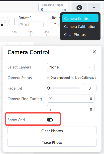
If the grid affects the image, you can turn off the grid display in the camera controls.
2. Select "Absolute Coordinates" for the starting position, and draw a rectangle at the center position on the board.
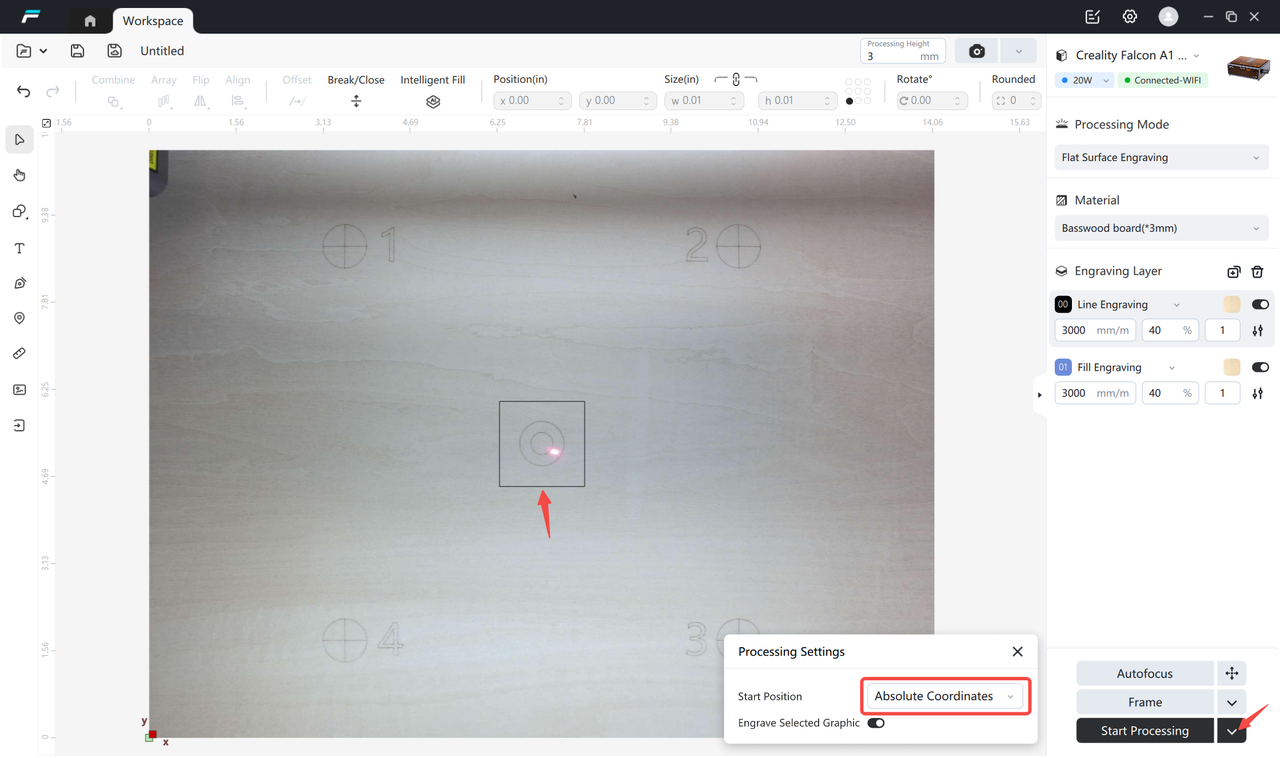
3. Carve the rectangle, after carving, click "Take Photo" again, use the mouse wheel to zoom in on the canvas to view the photo, if there is a deviation between the rectangle and the actual carving position.
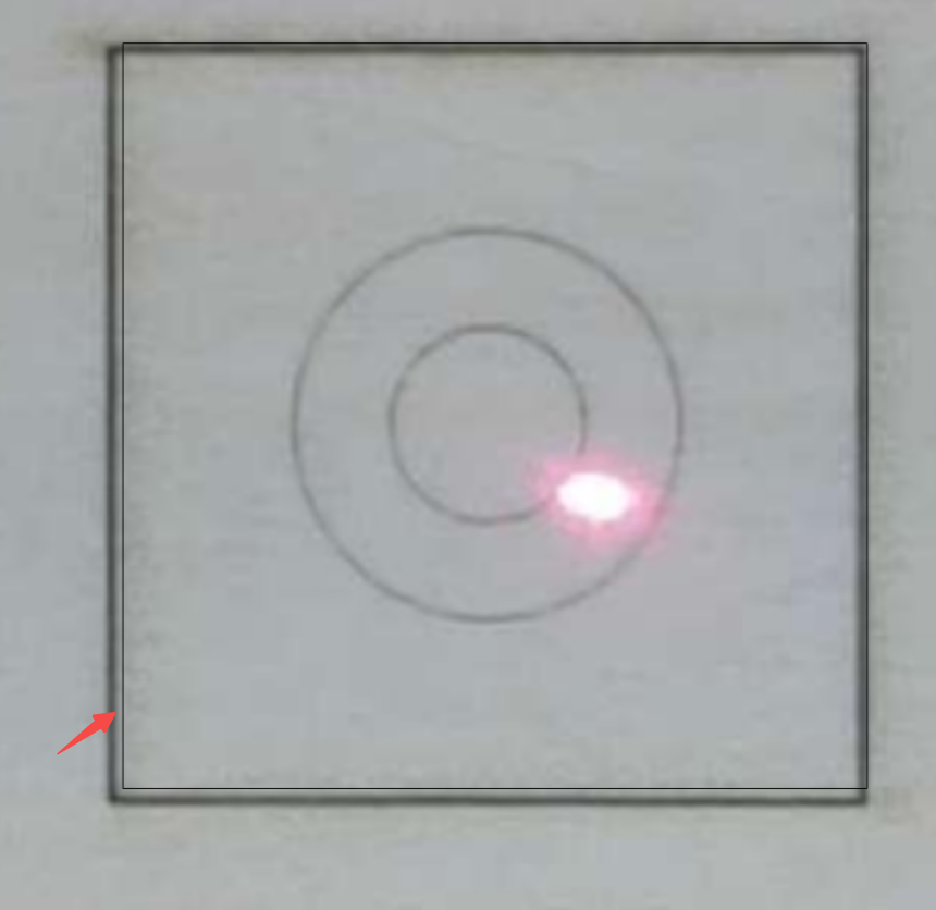
4.Open in [Camera Control], adjust the x and y coordinates until the images are completely aligned.
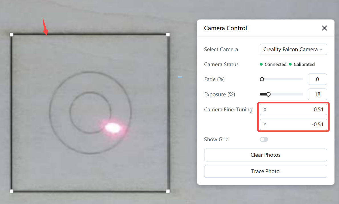
At this point, the fine-tuning work has been completed, and the central area can be precisely positioned for carving.