¶ Installation Example
¶ 1. Install the chuck onto the base plate
a. Align the bottom slot of the chuck with the slot on the base plate, then push it in.
b. Rotate the to lock the chuck to the base plate.
¶ 2. Install the tailstock to the base plate
a. Rotate the top of the tailstock to raise the roller to half its height.
b. Align the bottom slot of the tailstock with the slot on the base plate, push in and lock the tailstock and the base plate.
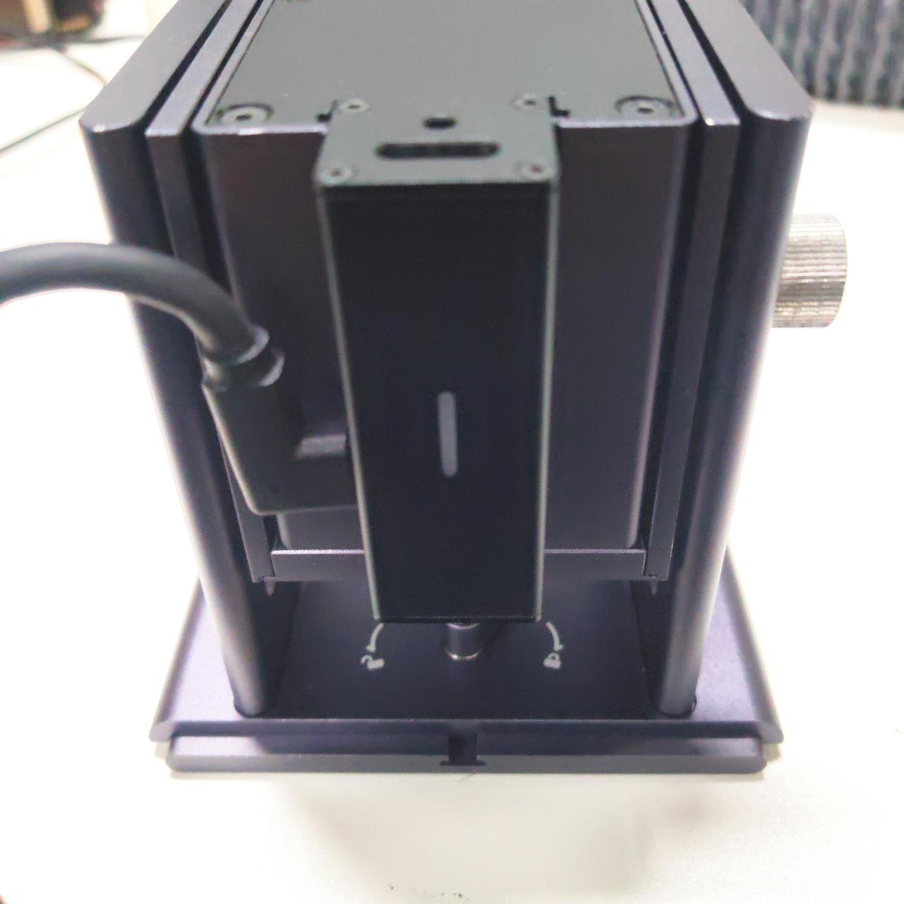
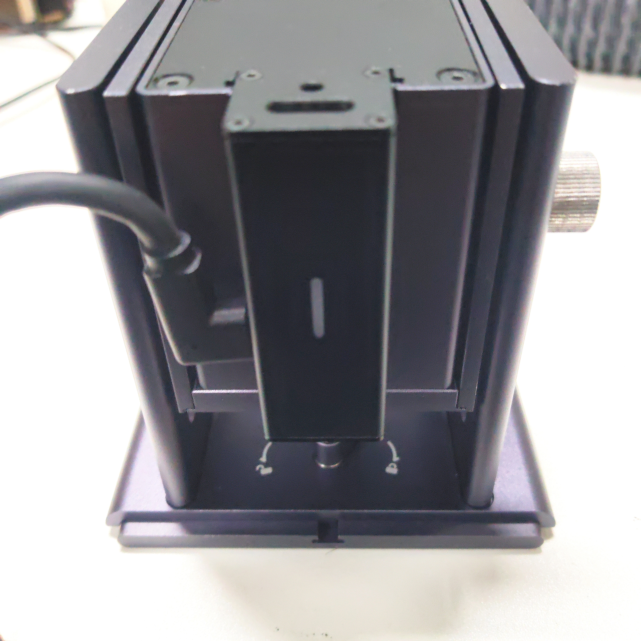
¶ 3. Adjust the chuck angle
a. Rotating the chuck rotation counterclockwise can adjust the chuck rotation angle.
b. Rotating the chuck clockwise can lock the current rotation angle of the chuck.
¶ 4. Install the jaws on the chuck
a. Place the clamping jaw on the chuck and lock it with screws.
¶ 5. Install the stud on the chuck
a. Screw the stud into the threaded hole of the chuck.
¶ 6. Install the laser auxiliary line module on the chuck
a. Align the positioning post of the laser auxiliary line module with the mounting hole on the chuck.
¶ 7. Install the motor module on the chuck onto the Roller
a. Rotate the chuck counterclockwise and rotate the chuck 180 degrees.
b. After rotating the lever counterclockwise, remove the motor module.
c. Loosen the nut at position ①, align the motor module slot with the Roller slot, and push the motor module into the Roller.
d. Gently push the motor module with your left hand, and turn the black roller 1-2 times with your right hand. During this process, the motor module will move slightly to the right and fit into the Roller.
e. Keep the left hand in the position of gently pushing the motor module, and rotate the lever to lock the motor module with the Roller.
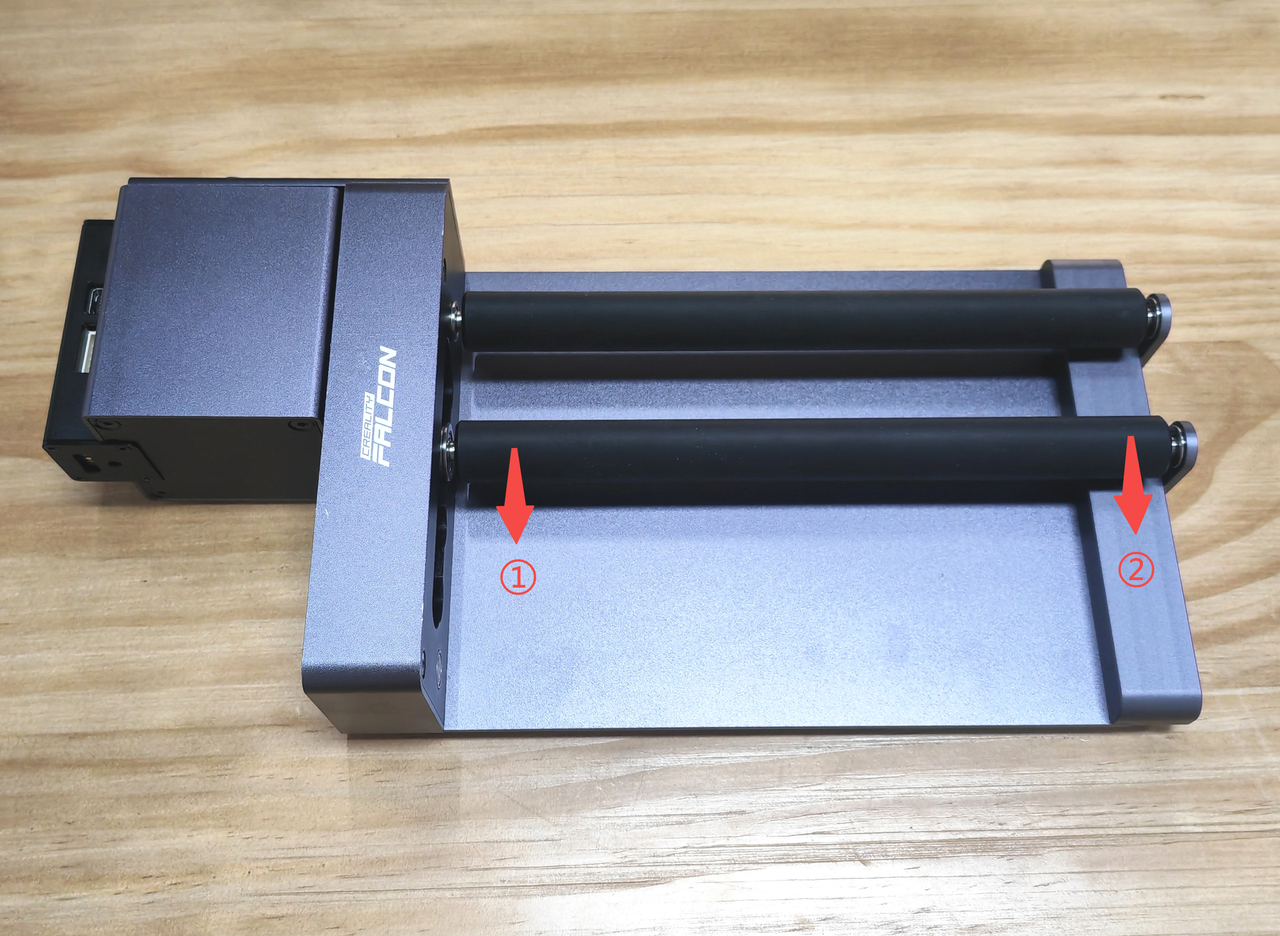
¶ 8. Adjust the spacing between the rollers
a. First, move one side of the Roller.
b. Then, move the other side of the Roller.
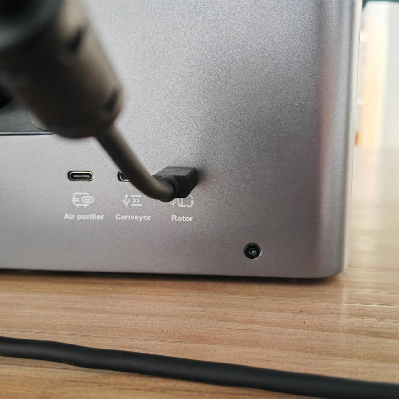
¶ 9. Connect the Rotary kit 2 to the engraving machine
Note: Before connecting the Rotary Kit 2 to the engraver, please check the height of the internal working space of the engraver. If the height is insufficient to accommodate the Rotary Kit 2, please first install heightening columns on the engraver.
a. Connect to T1 Machine
Use the Mini-A data cable included with the Rotary Kit 2 to connect T1 and the Rotary Kit 2 sequentially.
b. Connect to A1C Machine
Use the Mini-A data cable included with the Rotary Kit 2 to connect A1C and the Rotary Kit 2 sequentially.
c. Connect to A1/A1 Pro Machine
Use the Rotary Kit 2 connection cable standard with A1/A1 Pro to connect A1/A1 Pro and the Rotary Kit 2 sequentially.
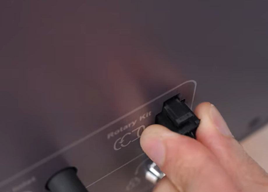
d. Connect to Falcon2/Falcon2 Pro Machine
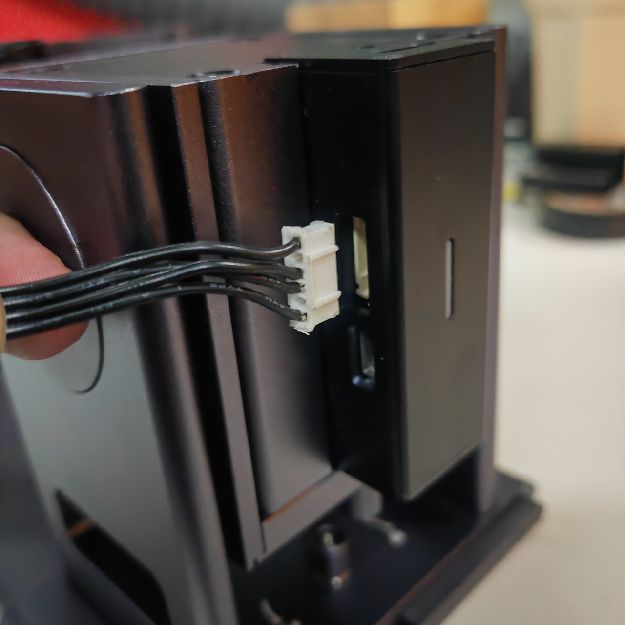
Pull out the Falcon2/Falcon2 Pro Y-axis motor cable and connect the 6-pin motor cable that comes standard with the Rotary Kit 2.
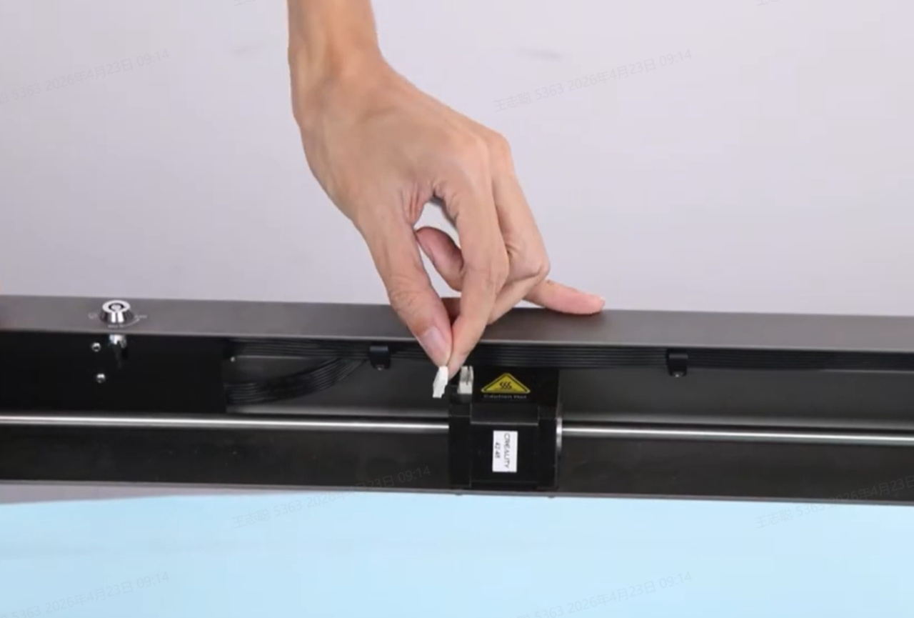
Connect the other end of the 6-pin motor cable standard with the Rotary Kit 2 to the Rotary Kit 2.
¶ Carving Example
¶ Carve using a Rotary Chuck 2
1. Use the standard ruler to measure the perimeter of the carving material and record the data.
2. Use the first-order gripper/second-order gripper/stud to secure the carving material , place the Rotary Chuck on the carving machine, and connect the Rotary Chuck and the carving machine using a Mini-A data cable or a 6-pin motor cable.
3. Instructions:
① When using the Mini-A data cable, with the engraver connected and powered on, the power indicator on the Rotary Kit 2 lights up and the laser auxiliary line can be used.
② When using the 6-pin motor cable, the power indicator on the Rotary Kit 2 does not light up and the laser auxiliary line cannot be used.
Caution: Avoid direct exposure of the laser guide line to human eyes.
When using the Mini-A data cable, with the engraver connected and powered on, pressing the switch on the back of the chuck can turn the laser guide line on or off.
4. To ensure that the laser engraving point falls on the central axis of rotation of the engraving material, adjust the position of the chuck so that the green laser auxiliary line coincides with the laser point of the engraving machine.
5. Open Falcon Design Space, connect the engraver. Then select Chuck-Rotary Engraving in Processing Mode, and click Auto Focus to perform the auto-focus operation (or manually perform the focusing operation).
6. Enter the perimeter of the carving material, click to take a photo (machines without a camera do not support this function), then import the carving pattern and position it properly, set the rotation direction and pattern size, and set the material and carving mode.
7. Click on the Frame to perform the border running operation, observe whether the carved area of the materials meets the expectations, and if there are no issues, click Start to begin carving.
¶ Carve using a Rotary Roller 2
1. Place the Roller in the working area of the engraving machine.
2. Connect the Rotary Roller to the engraving machine using a Mini-A cable or a 6-pin motor cable.
3. Place the carving material on the Roller, adjust the position of the Rotary Roller so that the laser point of the carving machine falls on the central axis of the material.
4. Open Falcon Design Space, connect the engraver. Then select Roller-Rotary Engraving in Processing Mode, and click Auto Focus to perform the auto-focus operation (or perform the focusing operation manually).
5. ① Click to take a photo (machines without a camera do not support this function), ② Import the carving pattern and position it properly, ③ Set the rotation direction and pattern size, ④ Set the material and carving mode.
6. Click on the Frame to perform the border running operation, observe whether the laser engraving area meets the expectations, and if there are no issues, click Start to begin engraving.