¶ Required Equipment for Installation
The following materials from the package are required to assemble the nozzle. The list is as follows:
- 0.4mm nozzle assembly ×4
- M4×12 screws × 8
- H2.5 allen wrench × 1
¶ Nozzle Assembly Installation
¶ 2.1 Pre-installation on the Nozzle Side
Take out the nozzle assembly, align the upper and lower hooks on the assembly with the fixed slots on the backplate hot end bracket. Slowly move toward the bracket, fit the hooks into the slots, then gently pull the nozzle body to the left by hand to complete the magnetic attachment and secure it in place.
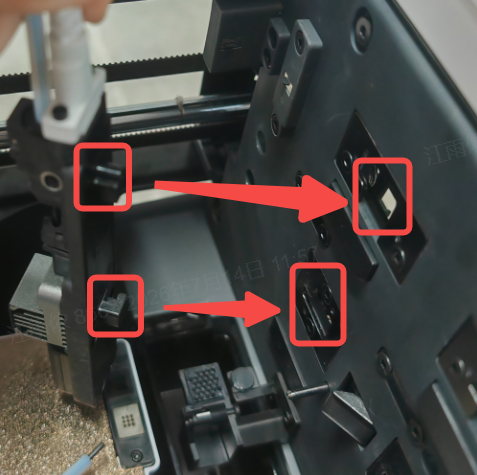
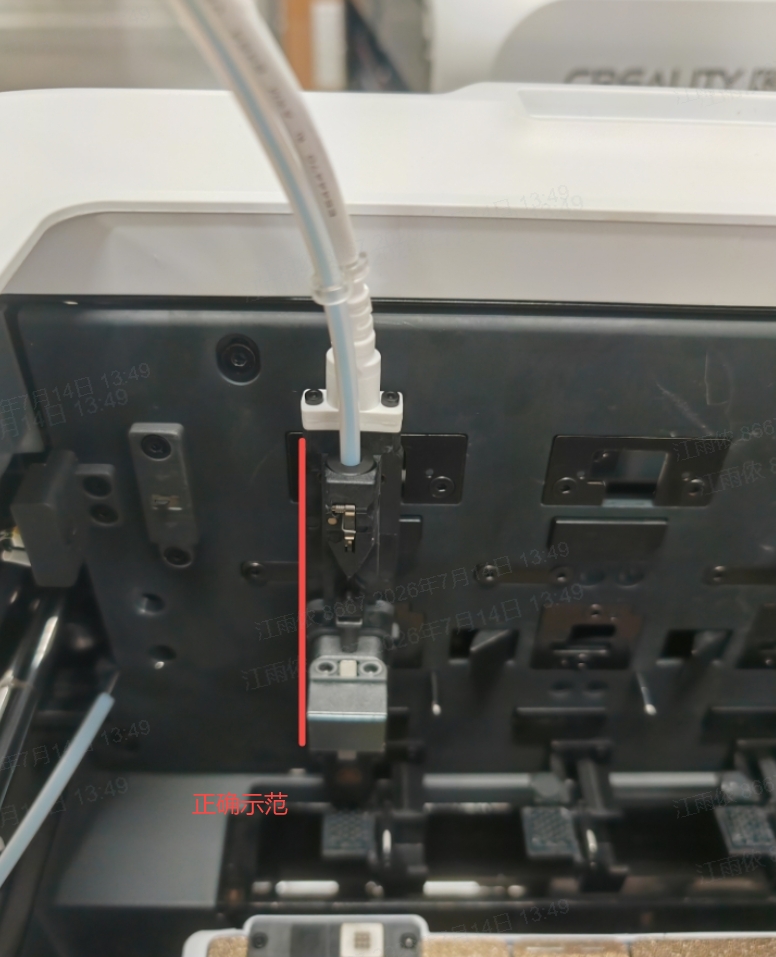
Installation verification: Gently shake the nozzle to confirm there is no looseness. The installation is qualified when the left side of the nozzle is fully flush against the slot.
 |
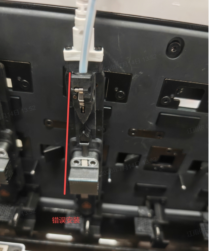 |
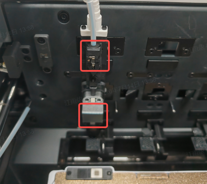
If the nozzle is misaligned during assembly, it must be removed and reinstalled. Please follow the steps below:
Use both hands to simultaneously grip the upper and lower ends of the nozzle as indicated by the red boxes in the image;
Pull horizontally toward the right side of the device to disengage the magnetic lock;
Pull straight outward to remove the entire nozzle assembly.
¶ 2.2 Cable Side Installation
As shown in the image, each nozzle must correspond one-to-one with the connector above it and must not be misaligned.
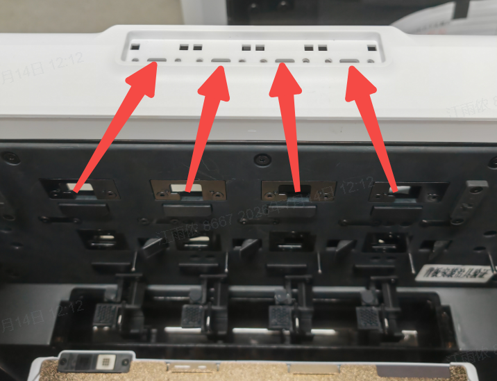
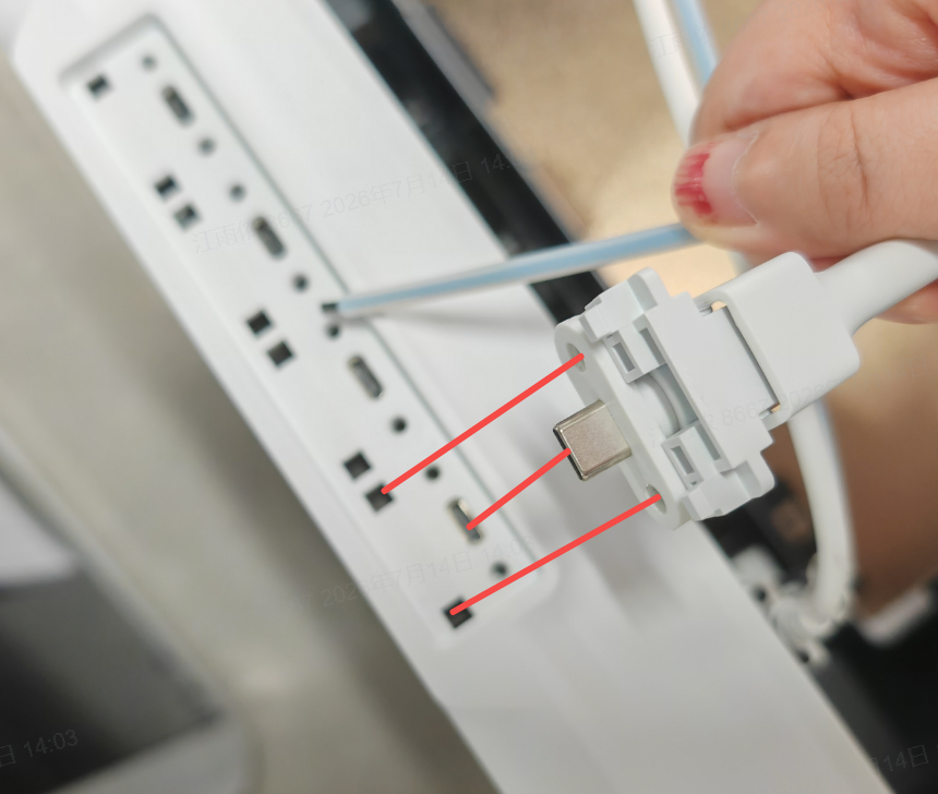
Align the nozzle communication connector with the slot opening and insert it steadily until it clicks into place.
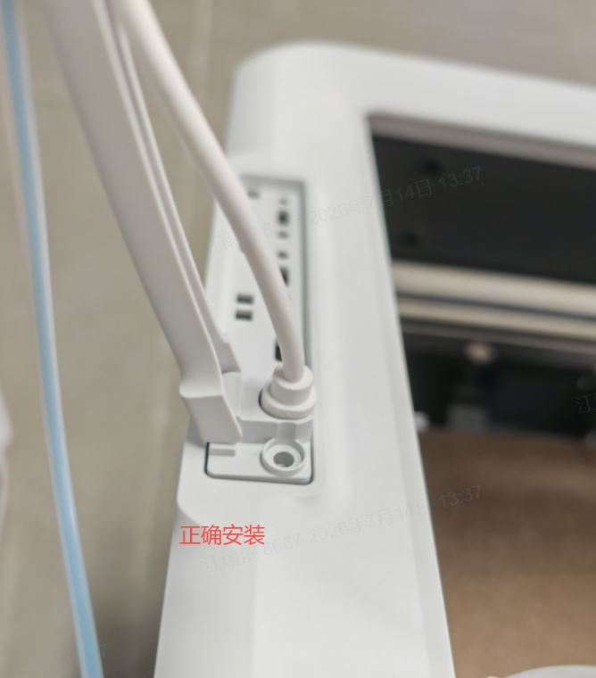
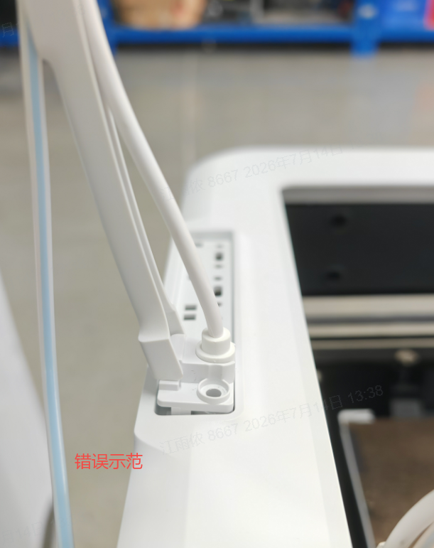
The image below shows the standard installed state: the connector is fully seated inside the socket with no exposed portion, indicating that the connection is properly made and communication is functioning normally.
|
|
Using the H2.5 allen wrench, secure the assembly with 2 ST4×14 self-tapping screws from the accessory pack.
¶ 2.3 Connecting the Automatic Filament Feeder
As shown in the image, insert the long PTFE tube on the cable side into the corresponding port of the automatic filament feeder.
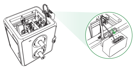
Installing All 4 Nozzles
Repeat Step 2 to install the remaining 3 nozzle assemblies.