¶ Tool
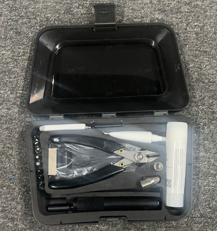
- K2 Plus Tool Box
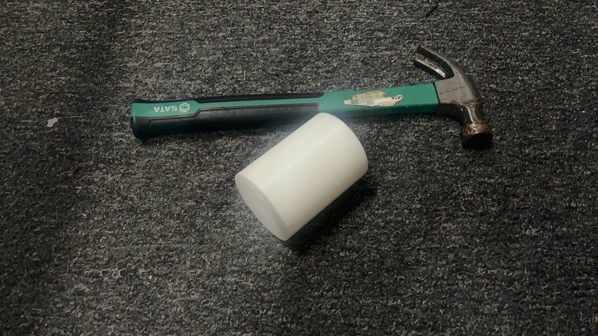
- Hammer/Pliers
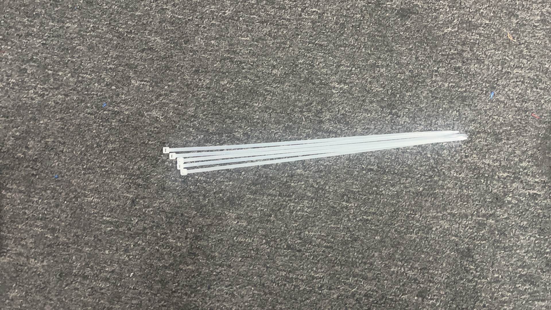
- Several Cable Ties
- 3M Tape/Foam Tape
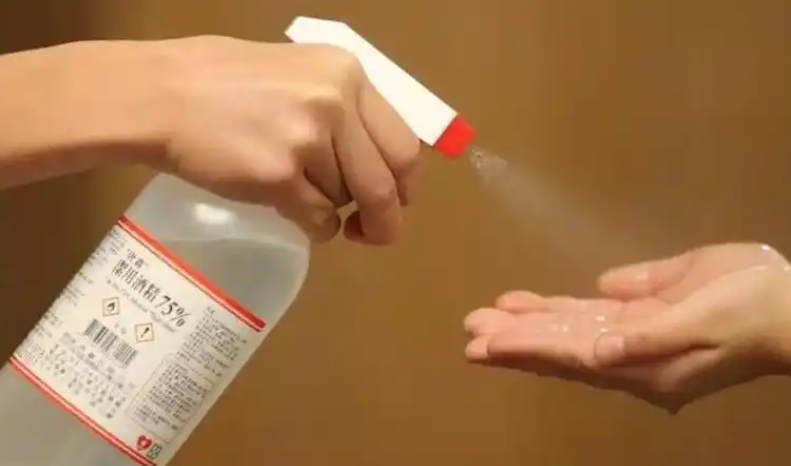
- Alcohol
- Print cube or cylinder/board models in advance, refer to the download file: Creality Cloud Cube Test. For more test models, please click the website: Creality Cloud Test Model
|
|
|
|
¶ Operation Steps
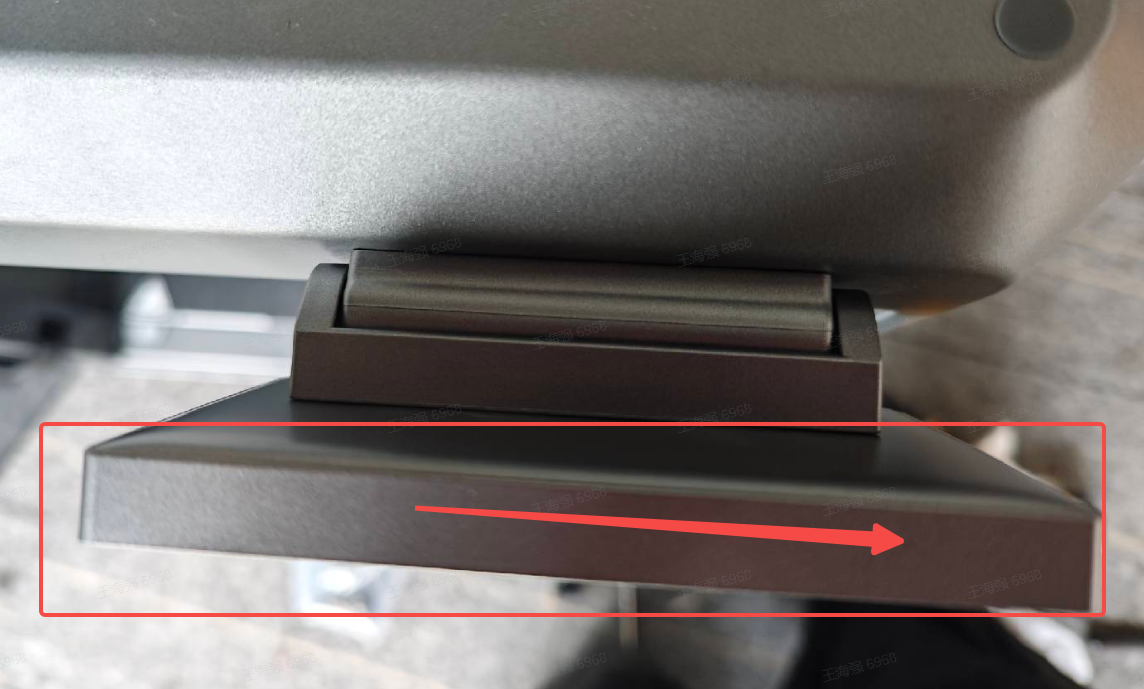
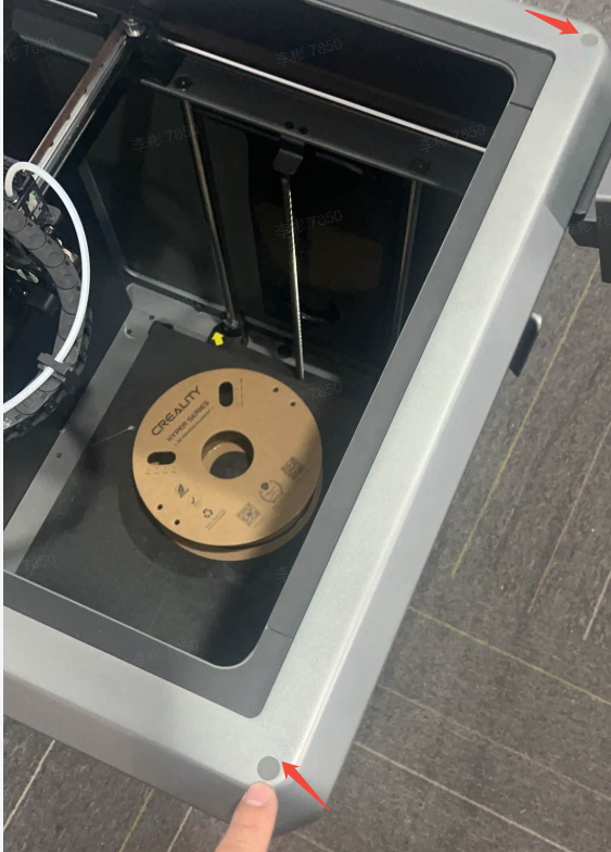
¶ Remove the spool holder, mainboard terminal on the upper frame, display screen and side panels
- First retract the filament, then turn off the printer.
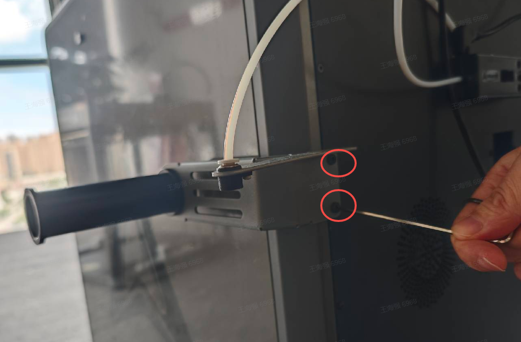
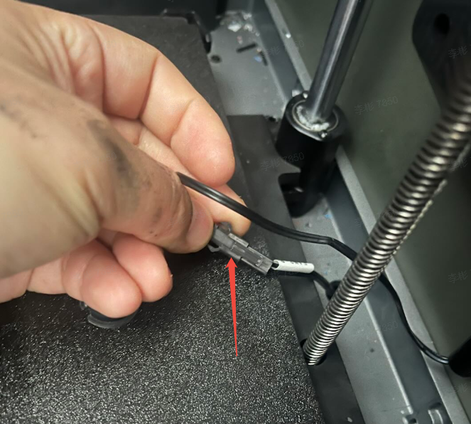
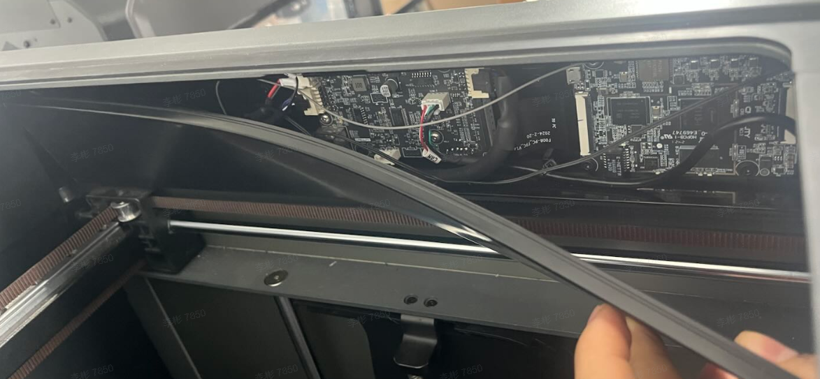
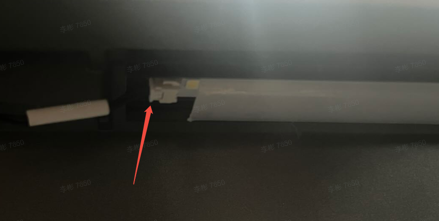
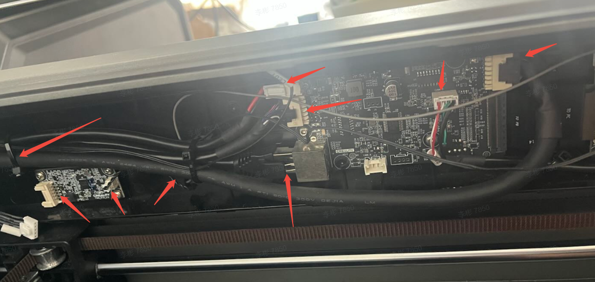
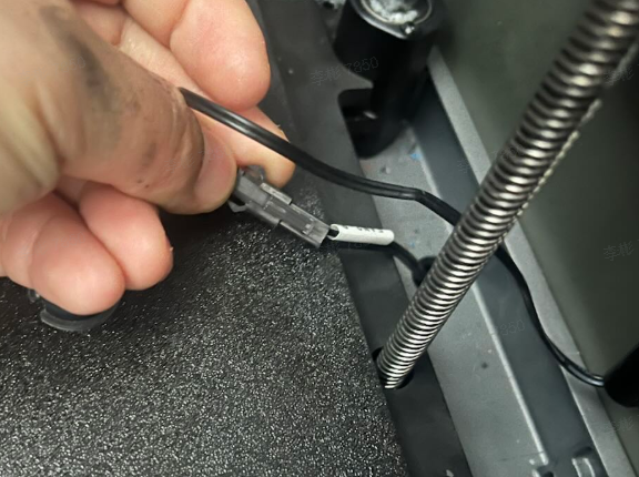
- As shown in the figure, remove the two fixing screws of the spool holder, unplug the side panel fan wires on both sides, right side RFID wire, power cable, Ethernet cable, communication bus, printhead drag chain bus, two LED strip wires and cable ties. Finally, remove the display screen.
Note: Do not cut any wires. After cutting the cable ties, check if any wires are damaged. Contact customer service (mail:cs@creality.com) for replacement if any wire damage is found.
|
|

|
|
|
|
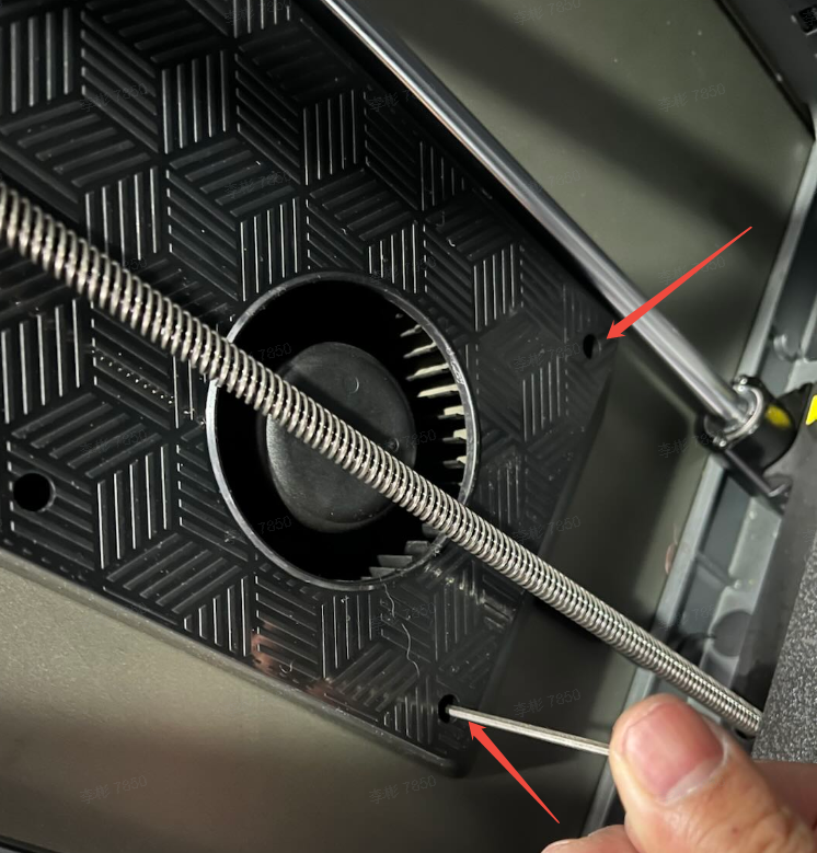
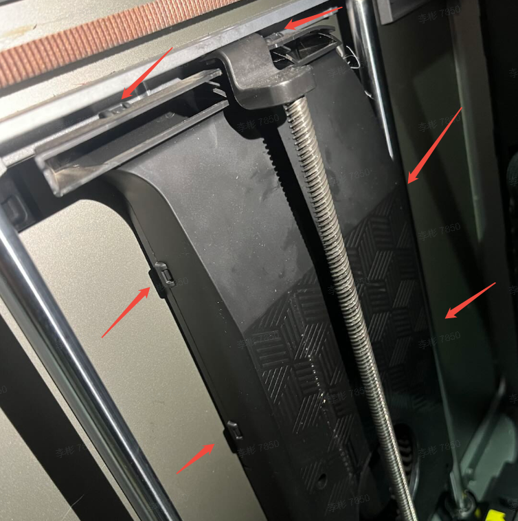
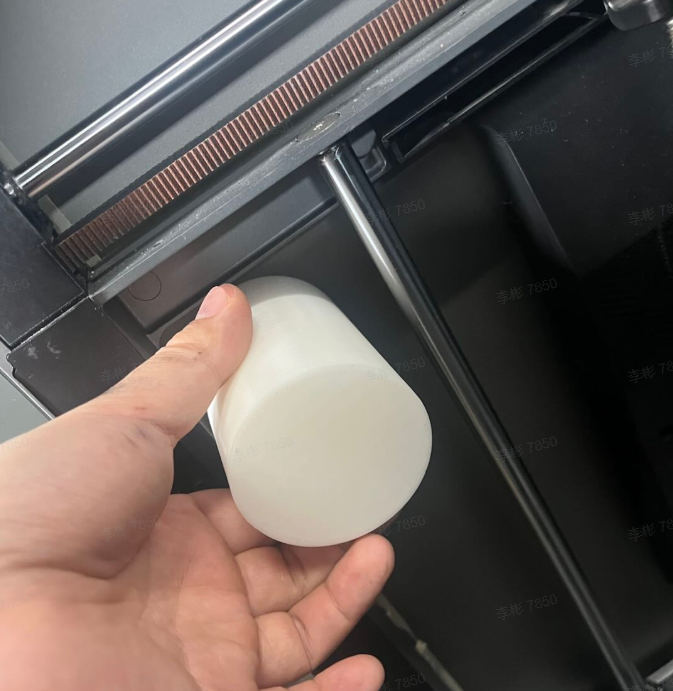
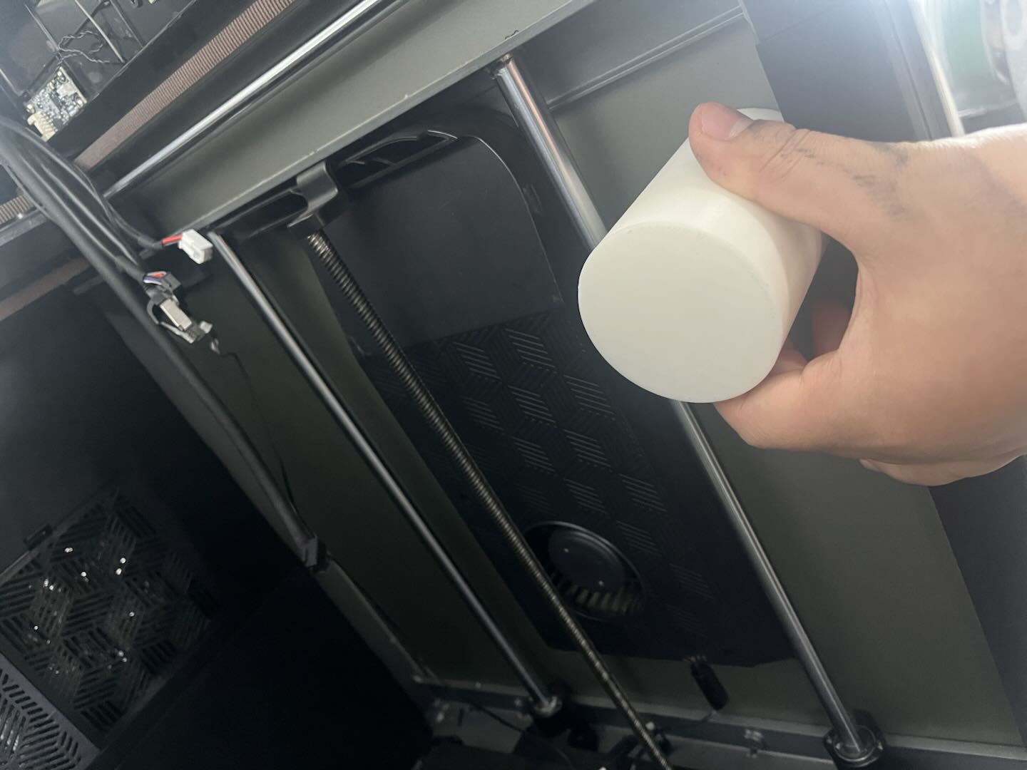
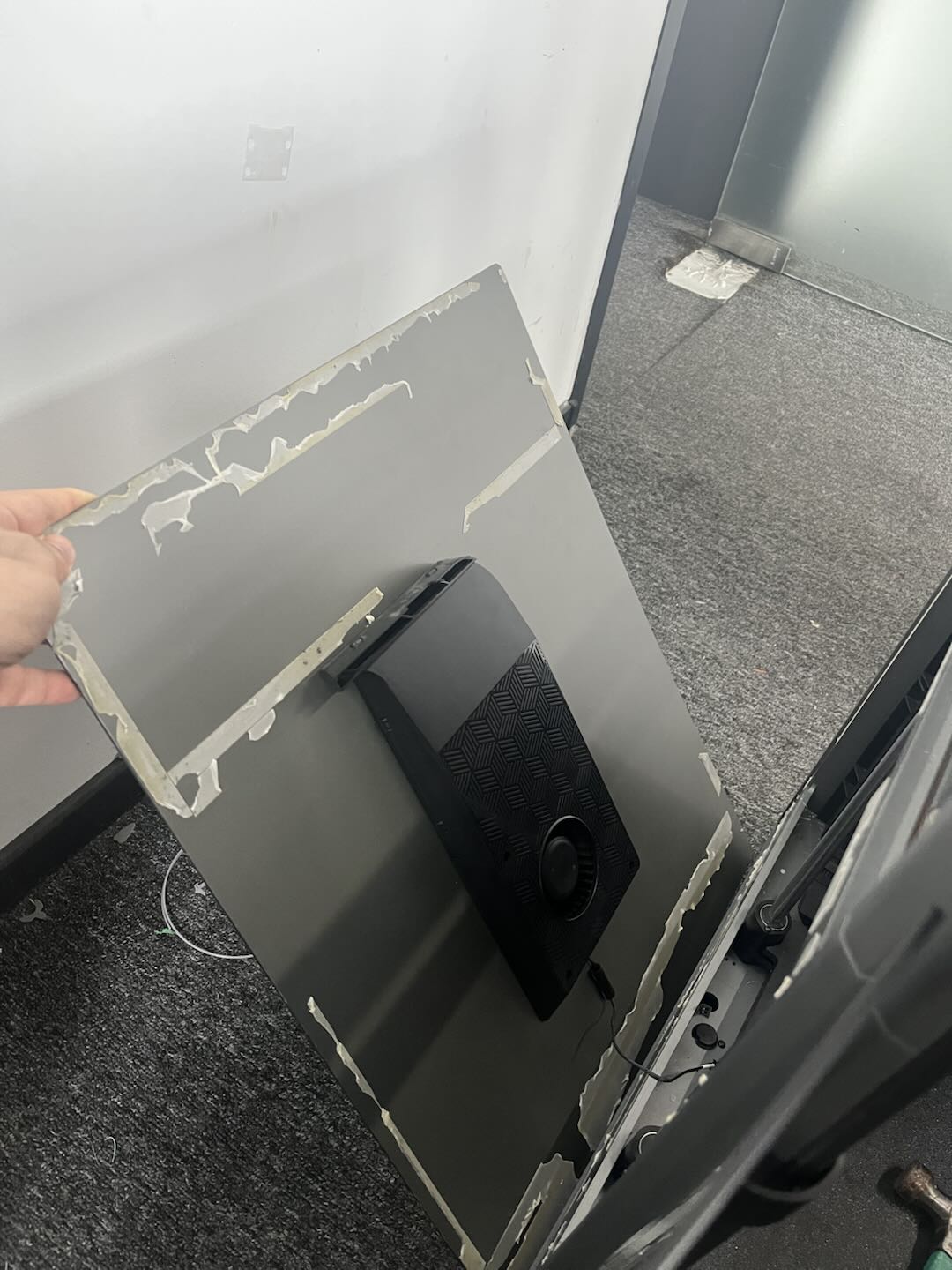
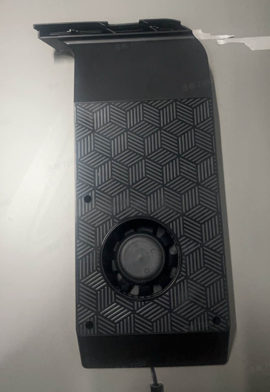
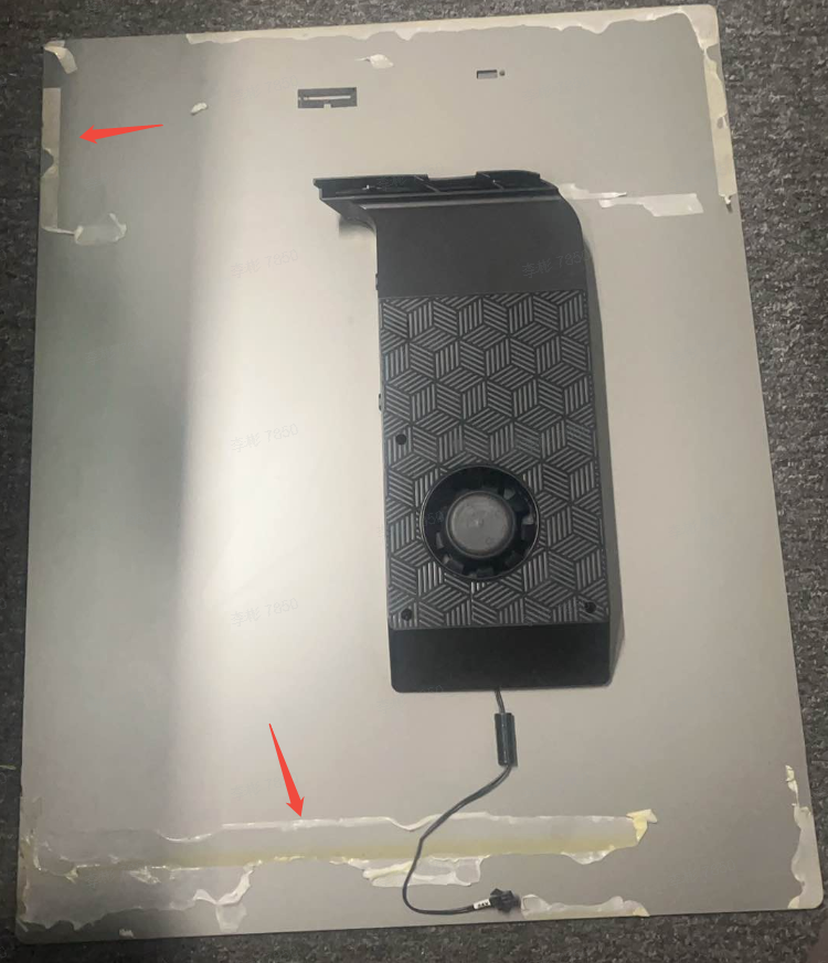
First, remove the 4 fixing screws of the auxiliary fans on both sides. Then loosen the 6 clasps to keep the fan cover in a detached state. Use pre-printed cube, cylinder/wooden board (Purpose: to increase the force bearing area) and a hammer to knock loose the side panel, allowing the adhesive on the side panel to detach.
|
|
 |
 |
 |
 |
¶ Remove the nozzle assembly and upper frame
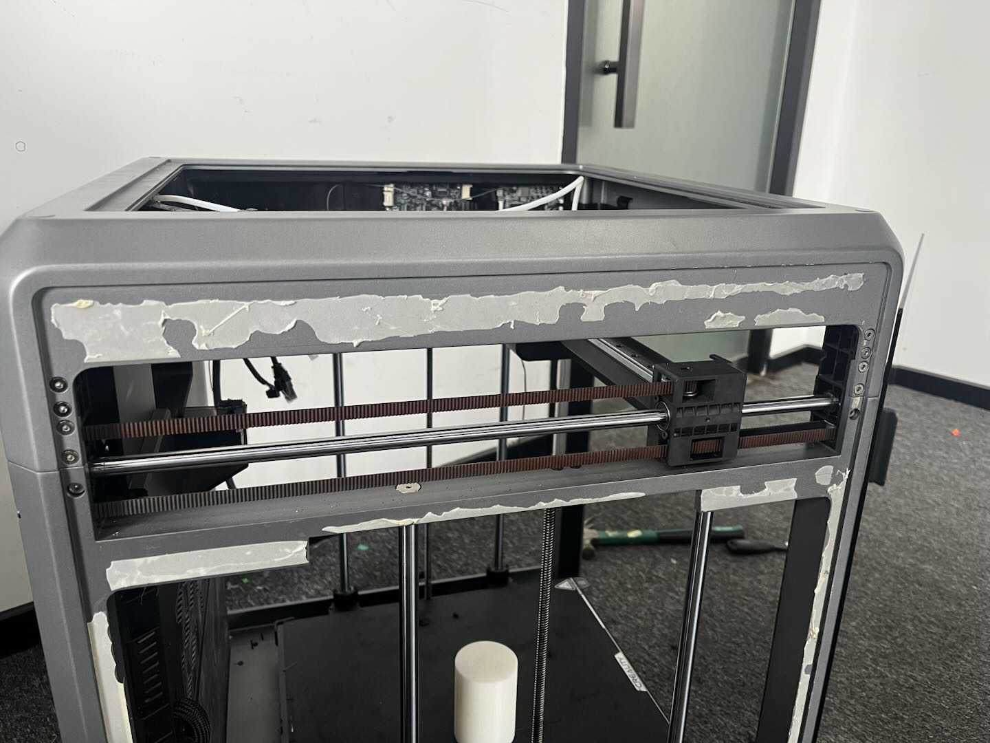
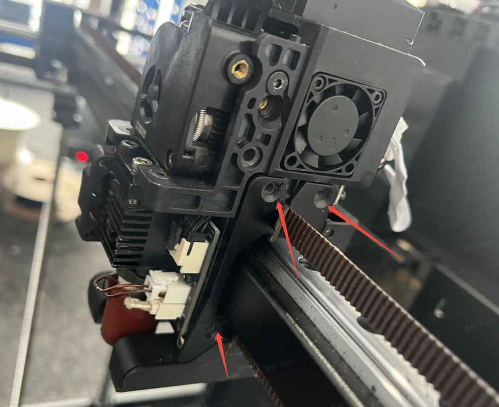
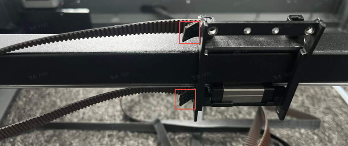
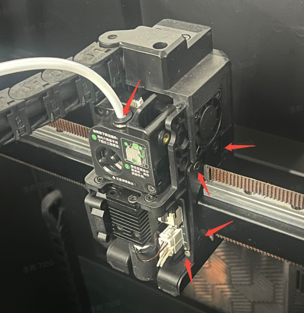
Remove the 3 fixing screws on both sides of the nozzle, then remove the nozzle assembly and disconnect the PTFE tube. Remove the belt (you can take a photo in advance to help remember the left and right positions of the belt, and the number of teeth reserved for the upper and lower belts, so that the position remains consistent during final assembly.)
|
|
 |
|
|
|
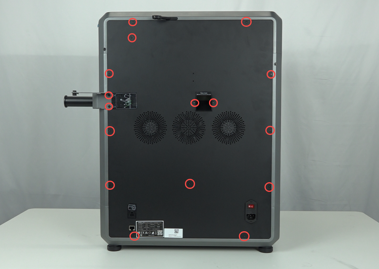
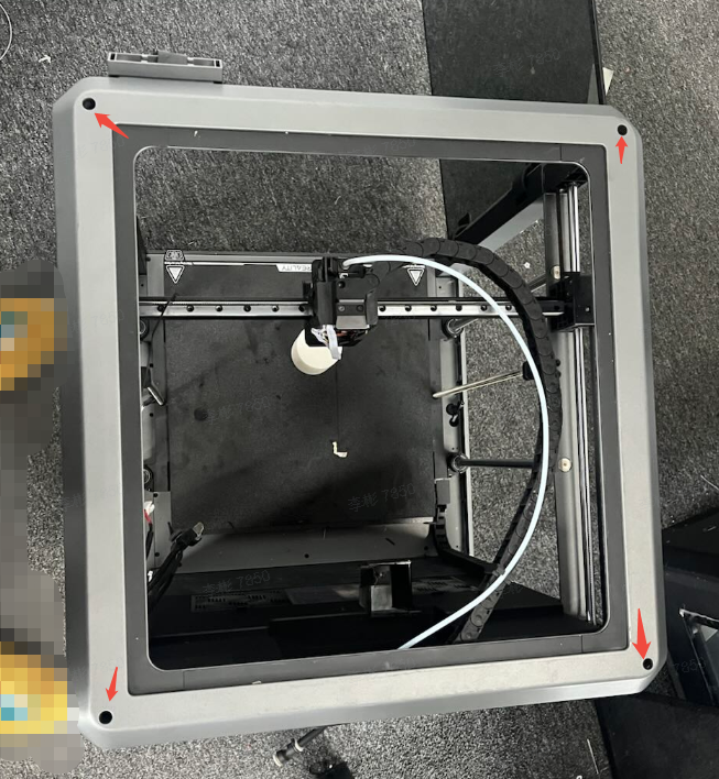
Remove the back panel first, then remove the fixing screws that secure the upper and lower frames on all four sides of the machine.
 |
 |
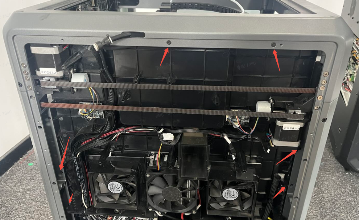
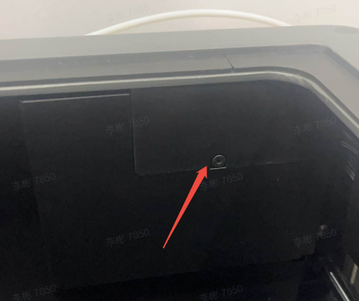
Meanwhile, remove the mounting screws on the upper frame plate and one screw on the front. Finally, remove the 4 rubber plugs on top of the upper frame and take out the 4 mounting screws inside.
 |
 |
 |
 |
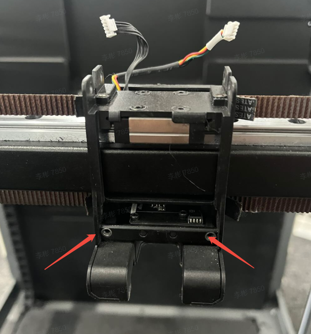
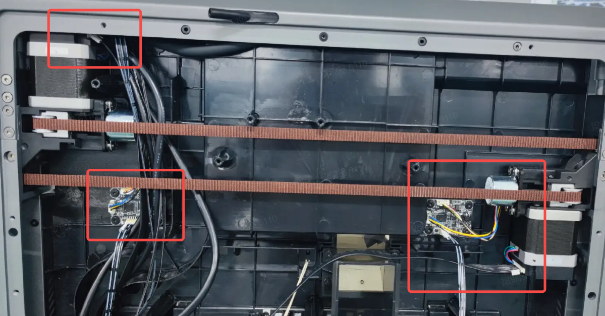
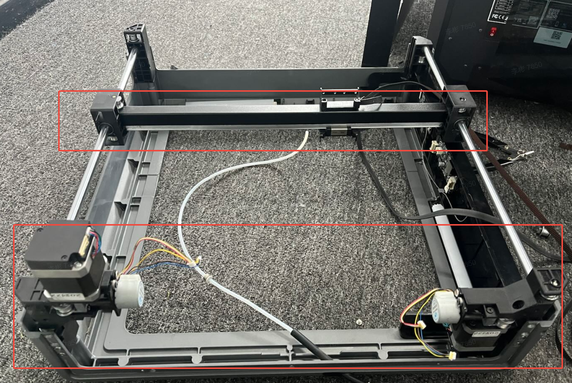
Unplug the X/Y motor cables, tensioner motor, and the terminal of the tensioner strain gauge.
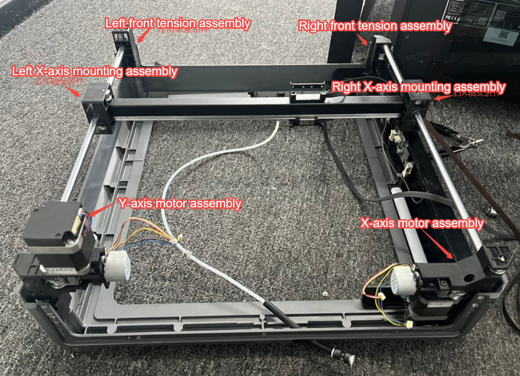
¶ Take out the upper frame and replace the corresponding module
Replace the corresponding parts according to the faulty module. Right front tension assembly (SKU: 2102013344), left front tension assembly (SKU: 2102013345), X-axis motor assembly (SKU: 2102013352), Y-axis motor assembly (SKU: 2102013353), right X-axis mounting assembly (SKU: 2102013346), left X-axis mounting assembly (SKU: 2102013343).
Note:
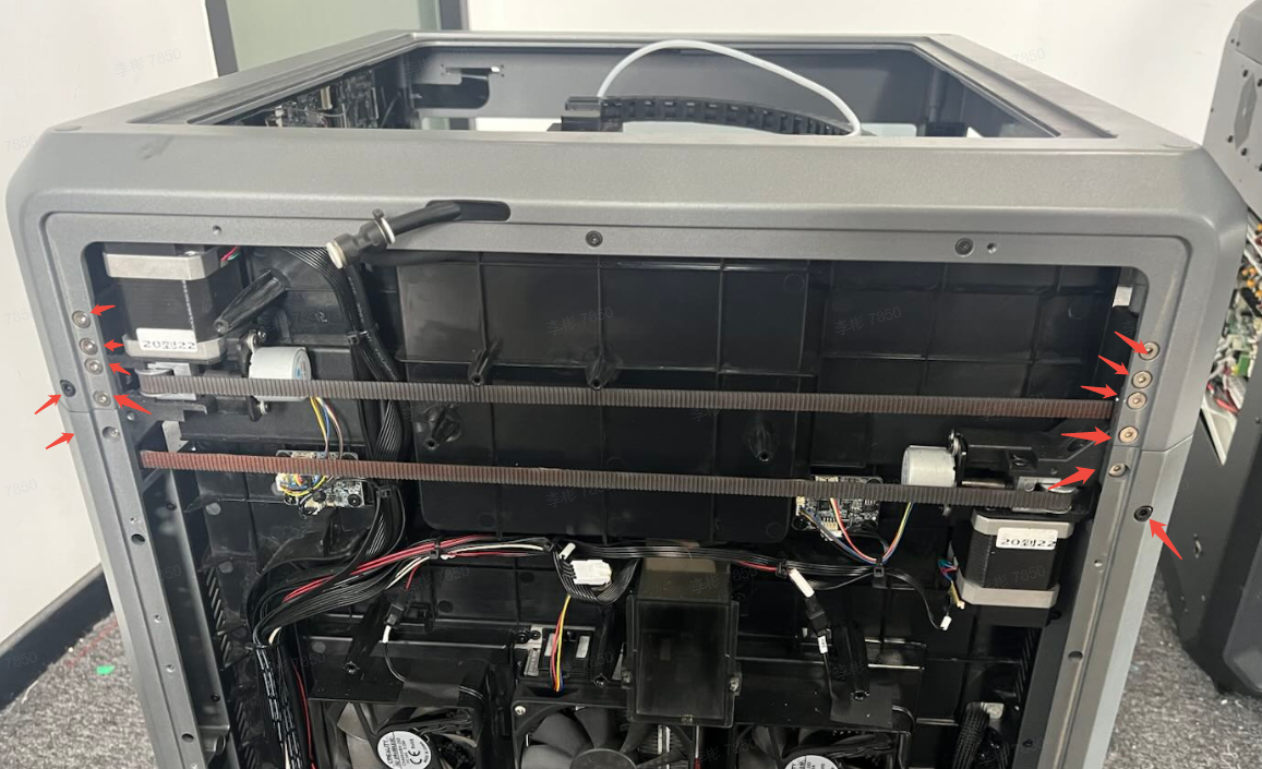
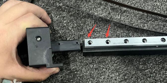
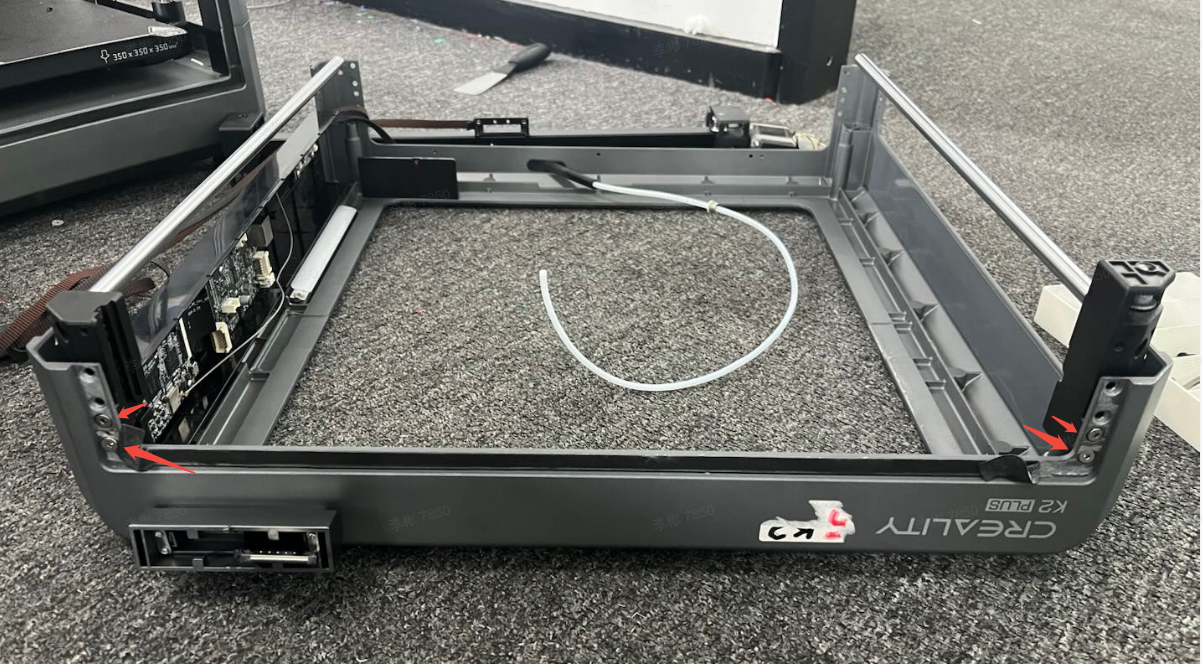
1. The left/right X-axis mounting assemblies are fixed on the guide rail tube. You need to remove the two fixing screws at the farthest ends on both sides of the guide rail.
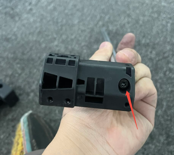
2. To remove the left/right front tensioning assemblies, you need to remove the fixing screws at the Y-axis module end.
 |
 |
|
¶ Install the upper frame and thread the belt
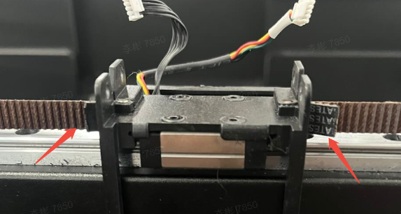
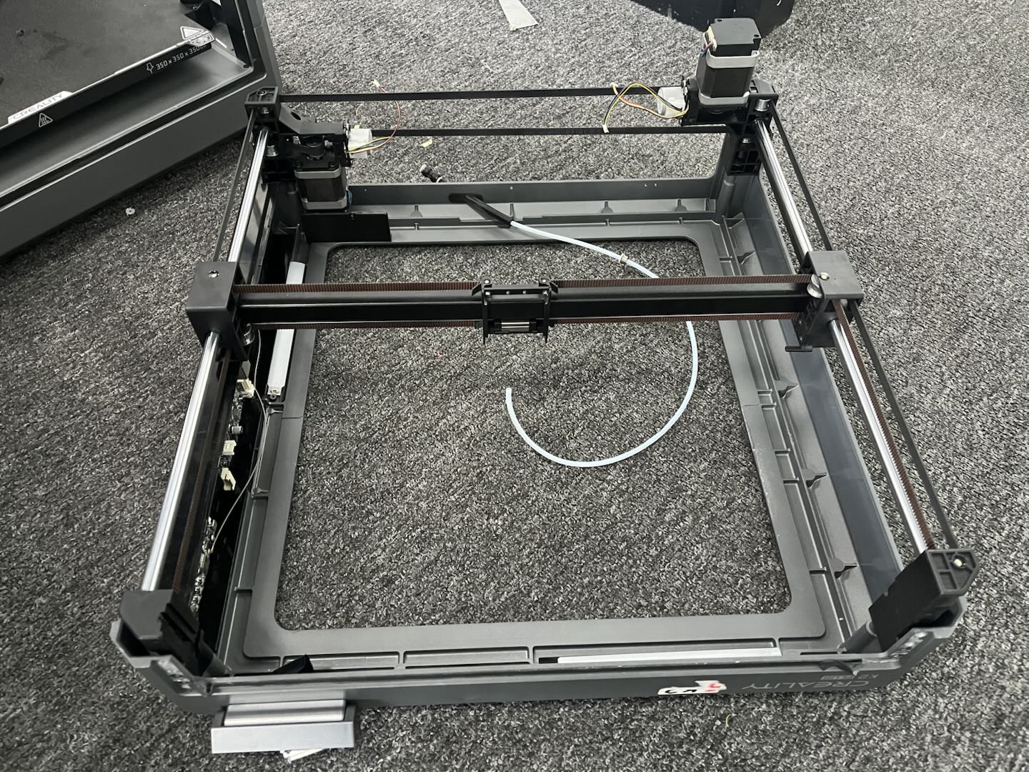
First, secure the Y-axis optical shaft and left/right front tensioner assemblies, then fix them onto the upper frame with screws (do not tighten the screws to leave room for assembly). After installation, insert the X-axis into the optical shaft, and finally secure the X/Y motor assembly.
 |
 |
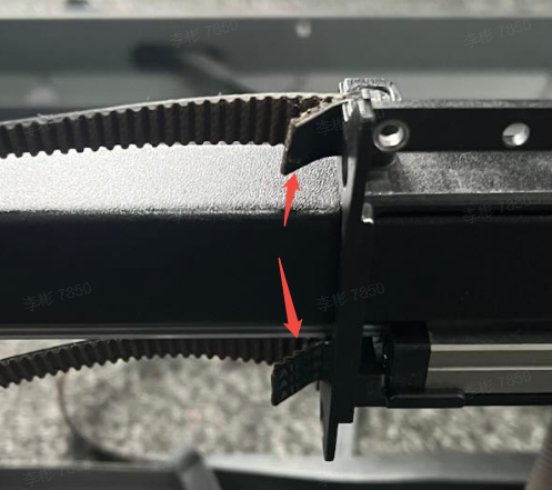
First secure one end of the belt, then follow the same routing path as when removing the belt. When securing the other end, make sure the number of teeth on the reserved length at both ends is equal. For the other belt, also ensure the number of teeth on the reserved length at both ends is equal.
¶ Lock the frame and nozzle assembly
After assembling the upper frame, insert it into the middle column of the printer.
Caution: Do not break the filament.
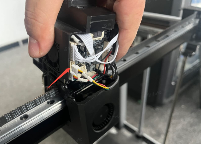
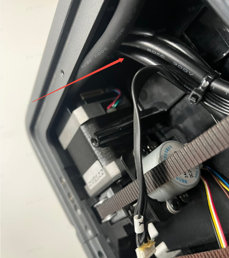
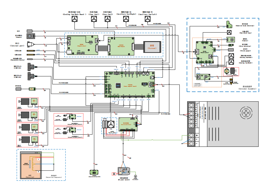
After installation, thread all the backplate wires through the X-axis motor assembly one by one, plug in the terminals, secure with zip ties. For wiring reference, please check the K2 Plus electrical wiring diagram.
K2 Plus electrical wiring diagram
After installing the upper frame, secure the fixing screws and motor wires on the backplate, then install the nozzle assembly onto the X-axis slider. Tighten the screws, fix the heat break fan wire and insert the PTFE tube.
¶ Install the auxiliary fan and the left and right side panels
Use the clasps to secure the housing of the left and right auxiliary fans, then tighten the screws.
Spray alcohol on the residual glue of the side panel and clean it thoroughly (if the glue isn't too dirty or messy, you can skip cleaning and apply directly). Apply new glue and attach properly, then connect the terminals of the two auxiliary fans.
 |
 |
After assembling the machine, check again to ensure there are no improper installations, disconnected or incorrectly connected wires. Once confirmed, proceed with power-on self-check.
¶ Friendly Reminder
If you still haven't resolved the issue after following the steps in this document, or if you encounter any difficulties during the process, you can click the right corner of the wiki page online support to contact our after-sales team for more help.