¶ Step One
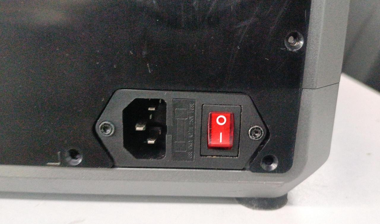
- Turn off the machine and unplug the power cord.
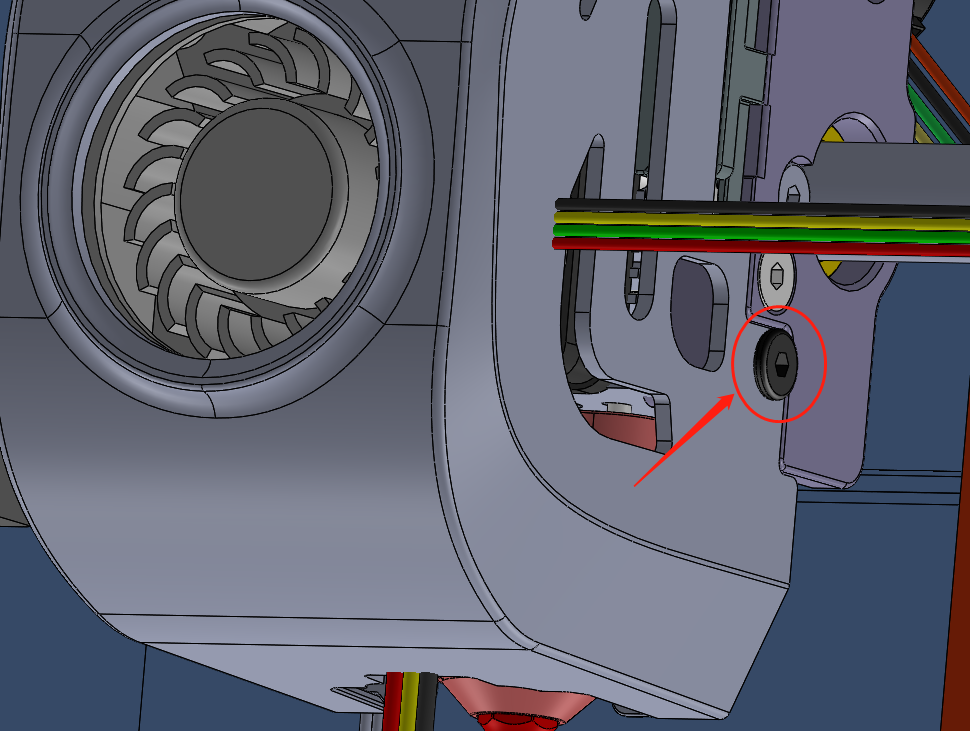
¶ Step Two
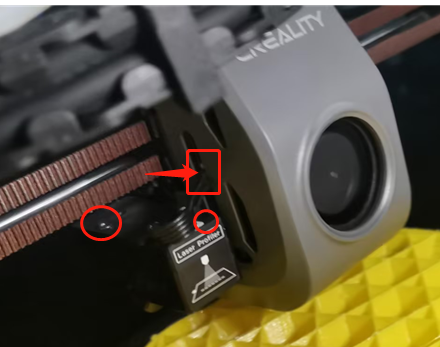
- To disconnect the transfer cable terminal on the left side of the hotend sub-board, use an Wrench to remove the two securing screws located above the AI Lidar and the two securing screws on the sides of the fan cover.


¶ Step Three
- Remove the fan cover and disconnect the model fan connector.
¶ Step Four
- Using an wrench, remove the three hex screws that secure the hotend sub-board.
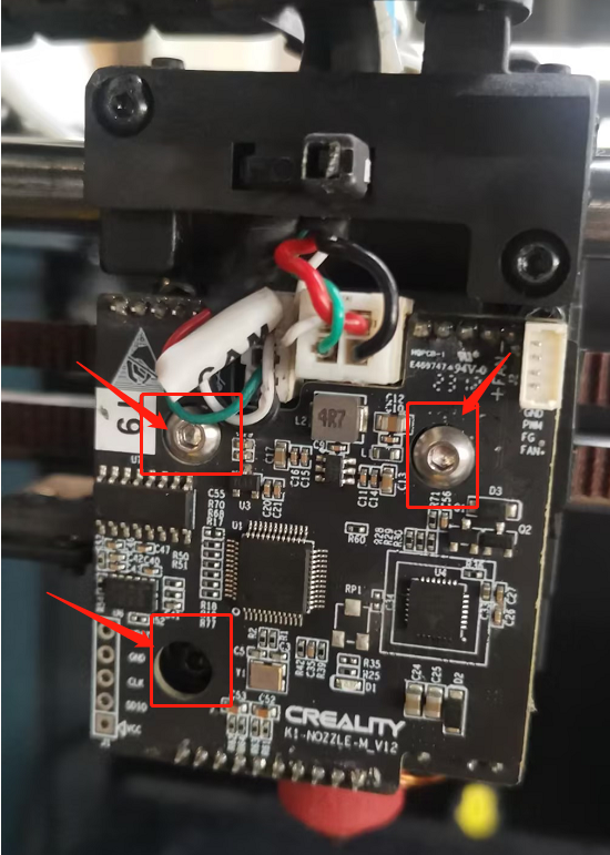
¶ Step Five
- Firstly, remove the stick glue, and disconnect all the wires on the Sub-board.
¶ Step Six
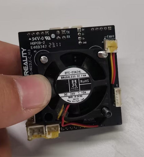
- Remove the fan connector from the old hotend sub-board, insert the connector into the slot of the new hotend sub-board with the fan label facing away from the sub-board, aligning it with the fan mounting holes. Insert three screws into the hotend sub-board and fan mounting holes to secure the hotend sub-board.
¶ Step Seven
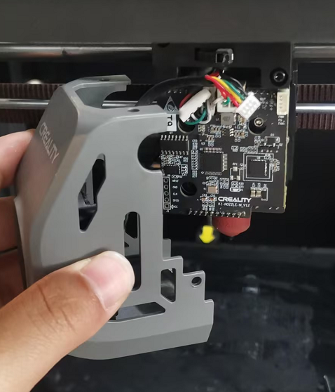
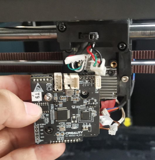
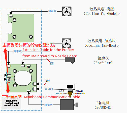
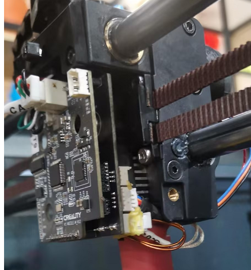
- Insert the terminals of the motor wire, ceramic heater ring wire, thermistor wire, Lidar module data transmission cable, and sub-board data transmission cable into their respective slots on the sub-board. Once inserted, use an Wrench to tighten the three hotend sub-board securing screws.
¶ Step Eight
- Ensure that the terminal positions, orientations, and engagement in the slots on the nozzle sub-board are correct.
¶ Step Nine
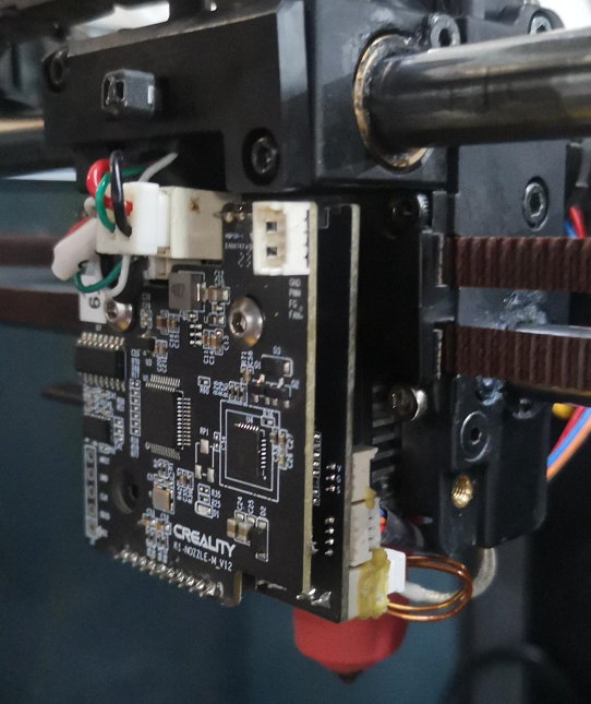
- Organize the nozzle wiring terminals neatly (you can refer to the picture to bundle them properly, to avoid the model fan pressing against the wiring when installing the nozzle cover, which could cause wire stripping and short circuits)
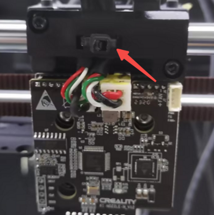
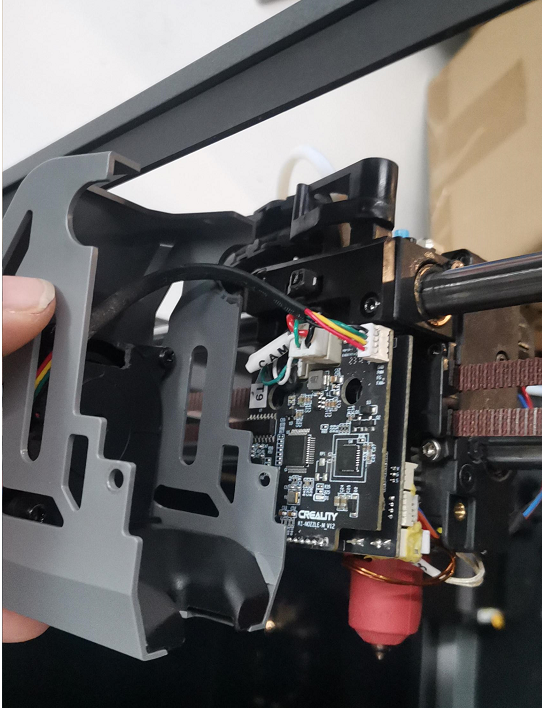
Take the fan cover and insert the model cooling fan connector into the corresponding terminal port on the front of the hotend sub-board. Tighten the two screws on the left and right sides of the fan cover to secure it.

¶ Step Ten
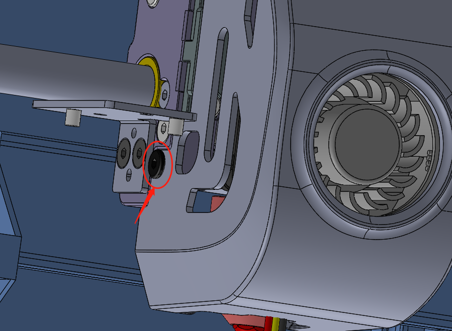
- Place the AI Lidar cable into the mounting hole shown in the square of the picture below. The alignment posts at the top of the module must be inserted into the alignment holes on the mounting bracket.