¶ Unbox & Setup Video
Creality Hi Unbox Video
https://www.crealitycloud.com/post-detail/677f2b8c06c912fef1158073
Creality Hi Combo Unbox Video
https://www.crealitycloud.com/post-detail/677f2c2f06c912fef1158607
Creality Hi Combo Operation Video
https://youtu.be/FCr17m1mgtU
¶ To Our Dear Users
Thank you for choosing Creality. For your convenience, please read through this User Manual before you start and follow the instructions provided carefully.
Creality is always ready to provide you with high-quality services. If you encounter any issues or have any questions when using our products, please use the contact information at the end of this manual to contact us. To further improve your user experience, you can find more about our devices via the following methods:
You can also visit our official website (https://www.creality.com) to find information regarding software, hardware, contact information, device instructions, device warranty information, and more.
¶ Firmware Upgrade
- You can upgrade the firmware directly through the device screen;
- You can upgrade the firmware via the Creality Cloud OTA;
- Please visit the official website https://www.creality.com, click on “Support → Download Center ” , select the corresponding model to download the required firmware, (Or click on“Creality Cloud → Downloads → Firmware”) , after installation is complete,you can use it.
¶ Product Operation and After-Sales Service Information
- You can log in to the Creality Official Wiki (https://wiki.creality.com) to explore more detailed after-sales service tutorials.
- Or contact our after-sales service center at +86 755 3396 5666, or send e-mail to cs@creality.com.

¶ NOTES
- Do not use the printer in any way other than described herein in order to avoid personal injury or property damage;
- Do not place the printer near any heat source or flammable or explosive objects. We suggest placing it in a well-ventilated, cool and dustless environment;
- Do not expose the printer to a violent vibration or any other unstable environment, as this may cause poor print quality;
- Please use recommended filaments to avoid clogging of the extrusion head and causing damage to the machine;
- Do not use the power cable of other products during installation. Always use a grounded three-prong power outlet, which accompanies the printer;
- Do not touch the nozzle and the heated bed during operation to avoid burns or personal injury;
- Do not wear gloves or wraps while operating the machine to prevent entrapment of movable parts that could cause crushing and cutting injuries to bodily parts;
- Use the provided tools to clean the filament from the extruder in time taking advantage of the residual temperature after printing. Do not touch the extruder directly when cleaning, otherwise it may cause burns;
- Clean the printer frequently. Clean the printer body with a dry cloth regularly after powering off the printer, wipe away dust, bonded print filament and foreign objects on the guide rails;
- Children under 10 years old should not use the printer without supervision, otherwise it may cause personal injury;
- Users should comply with the laws and regulations of the corresponding countries and regions where the equipment is located (used), abide by professional ethics, pay attention to safety obligations, and strictly prohibit the use of our products or equipment for any illegal purposes; Creality will not be responsible for any violators' legal liability under any circumstance;
- Tip: Do not plug in or unplug wires on a charged basis.
¶ 1. About the Printer

¶ 2. Parts List


¶ 3. Assembly Procedure
¶ 3.1 Install Gantry Frame Assembly
¶ 3.2 Gantry Frame Motor Wiring

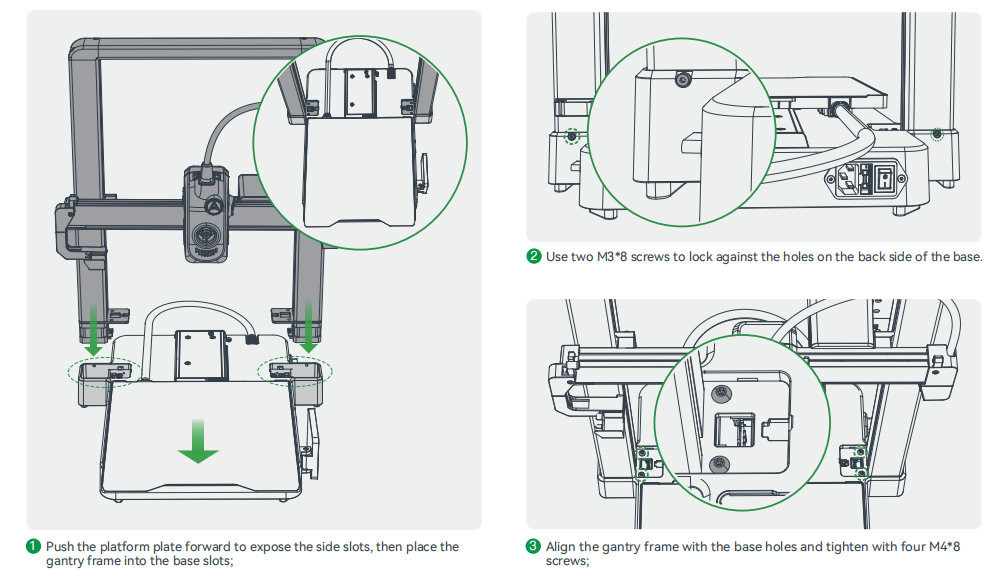
When installing the Z-axis motor covers, make sure the wires are pressed into the bottom of the wire channel to avoid the motor covers pinching the wires.
¶ 3.3 Install Spool Holder Assembly and Rotate Screen

¶ 3.4 Equipment Wiring

¶ 3.5 Connecting CFS
¶ Recommended Position for Creality Hi Combo
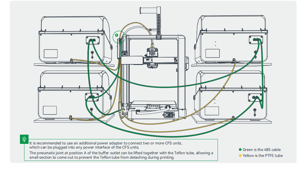
¶ 3.6 Connecting Multiple CFSs for Use
¶ 4. About the Power-on Guide and User Interface
¶ 4.1 Power-on guide

If any abnormalities occur during the self-check process, please refer to the FAQ to check for possible machine malfunctions;
Alternatively, scan the QR code for “fault reporting" to report the machine issue and seek assistance from the after-sales service for problem resolution.
The current interface is for reference only. Due to the continuous upgrading of functions, it shall be subject to the latest software/firmware UI published on the official website.
¶ 4.2 Overview of Equipment Interface
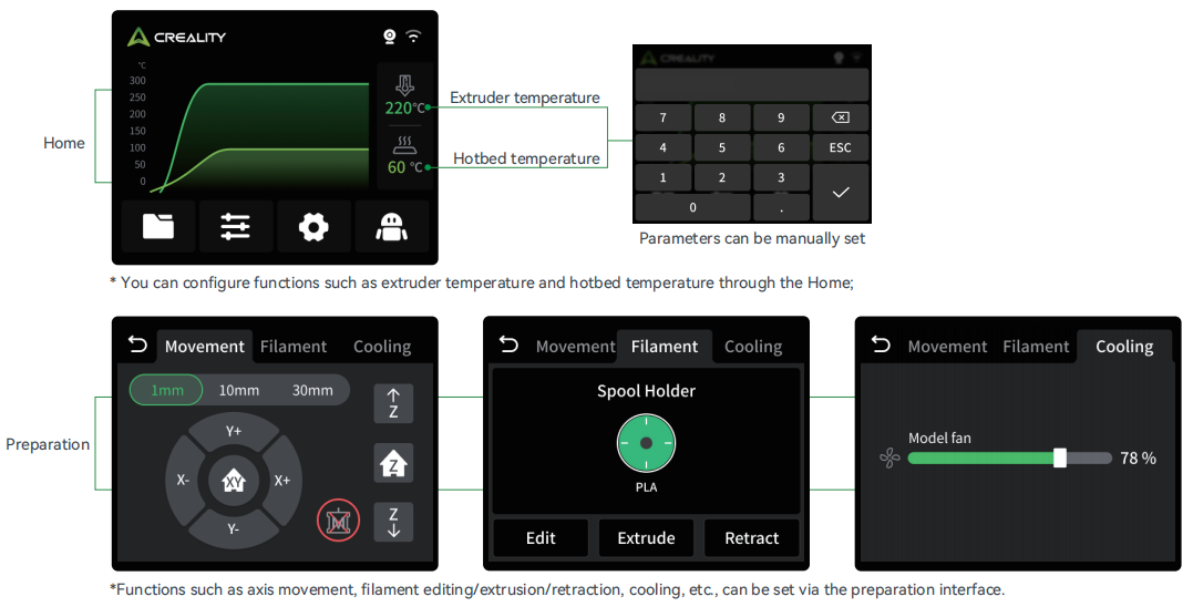
The current interface is for reference only. Due to the continuous upgrading of functions, it shall be subject to the latest software/firmware UI published on the official website.

The current interface is for reference only. Due to the continuous upgrading of functions, it shall be subject to the latest software/firmware UI published on the official website.

The current interface is for reference only. Due to the continuous upgrading of functions, it shall be subject to the latest software/firmware UI published on the official website.

The current interface is for reference only. Due to the continuous upgrading of functions, it shall be subject to the latest software/firmware UI published on the official website.
¶ 5. First Print
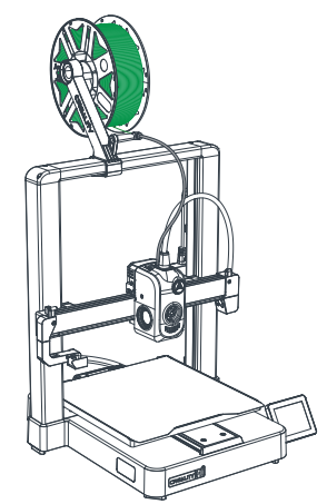
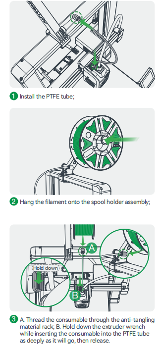
¶ 5.1 Spool Holder Filament Editing/Loading
Before initiating feeding, you may slightly pull the filament outward. If you cannot pull out the filament, it indicates that the teeth have already gripped the filament; click the feed button on the screen to initiate normal feeding. If you can pull out the filament, you need to repeat step 3
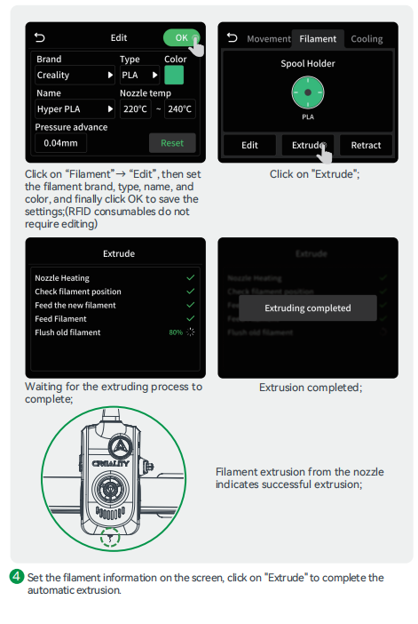
¶ 5.2 CFS Filament Editing/Loading

¶ 5.3 LAN Printing

Scan the QR code below to download the latest slicing software;

Tips:The computer and printer must be connected to the same LAN


The current interface is for reference only. Due to the continuous upgrading of functions, it shall be subject to the latest software/firmware UI published on the official website.
¶ 5.4 Creality Cloud printing


The current interface is for reference only. Due to the continuous upgrading of functions, it shall be subject to the latest software/firmware UI published on the official website.
¶ 5.5 USB flash disk Printing

The current interface is for reference only. Due to the continuous upgrading of functions, it shall be subject to the latest software/firmware UI published on the official website.
¶ 6. Functional Specification
¶ 6.1 RFID Filament Recognition
① Please use the RFID scanning function when the machine is not printing, as filament information will not be automatically recorded while printing;
② A "beep" sound indicates successful filament information reading;
③ The RFID-scanned filament information appears on the display screen. The user can click to edit, and after editing, click “OK” to save the filament information. At this point, the user can remove the old filament and replace it with a new one.
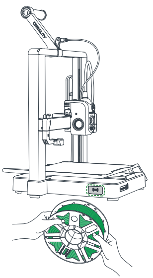
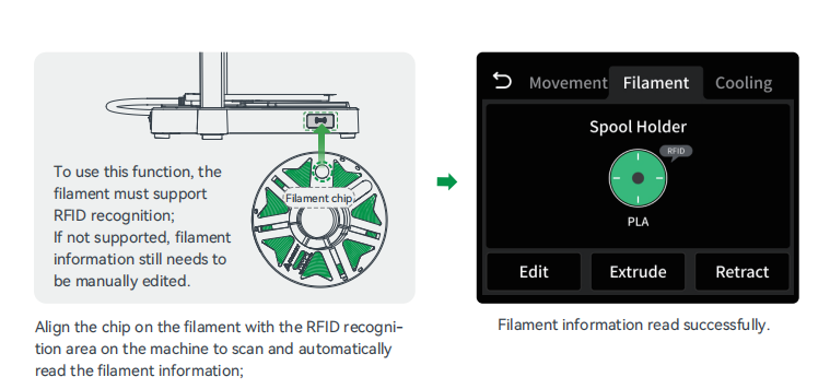
¶ 6.2 CFS Filament Management/Loading/Unloading
To avoid filament spool getting stuck, do not use cardboard spool with untreated edges or cardboard spool that are deformed as a whole;
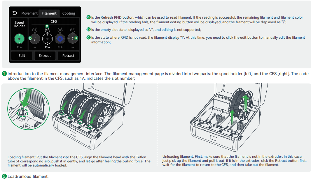
¶ 6.3 Auto Retraction

Do not manually retract the filament. Pulling out the filament manually may leave residue inside the extruder, and cause a blockage!
The current interface is for reference only. Due to the continuous upgrading of functions, it shall be subject to the latest software/firmware UI published on the official website.
¶ 7. Introduction of CFS
For more information about CFS, please refer to CFS (Creality Filament System)
¶ 8. Equipment Maintenance
¶ 8.1 Platform plate removal and maintenance

① Don't bend too much for daily use to prevent deformation and unusability;
② The printing platform is a perishable part, and it is recommended to replace it regularly to ensure that the first layer of the model sticks properly.
¶ 8.2 Optic Axis Maintenance
It is recommended to purchase lubricating grease for periodic lubrication maintenance of the optic axis and guide rail areas.

¶ 8.3 X-axis Belt Tension Adjustment
If the cutter fails to cut through the filament, adjust the X-axis belt tension; Loosen the screws as shown in the diagram to automatically release the belt tension, then tighten the screws.

¶ 8.4 PTFE Tube Replacement
During multi-color printing, a worn PTFE tube can cause feeding issues. recommend users check the condition of the PTFE tube weekly. If any wearis found,please replace it promptly to avoid affecting normal printiing.
¶ 9. Specifications

Due to the differences between different machine models, the actual objects and the images may differ. Please refer to the actual machine. The final explanation rights shall be reserved by Shenzhen Creality 3D Technology Co., Ltd.