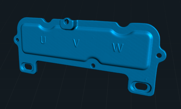
Today, we will discuss the scanning challenges of a complex category of workpieces—thin-walled parts.
As the name suggests, thin-walled parts refer to components with thin structural walls, such as sheet metal, enclosures, etc. The primary difficulty in scanning these parts lies in aligning data from both front and back surfaces. Due to their narrow sidewalls, feature-based alignment is challenging due to insufficient shared features, while marker-based alignment is hindered by the difficulty of attaching markers to the sides. The key to solving this issue lies in using auxiliary methods to achieve accurate data alignment.
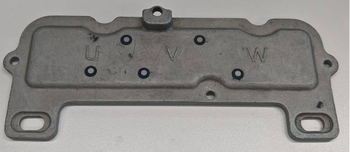
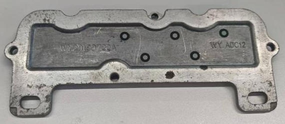
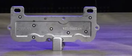
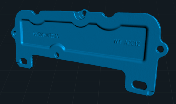
¶ Example: Thin-Walled Die-Casting Part
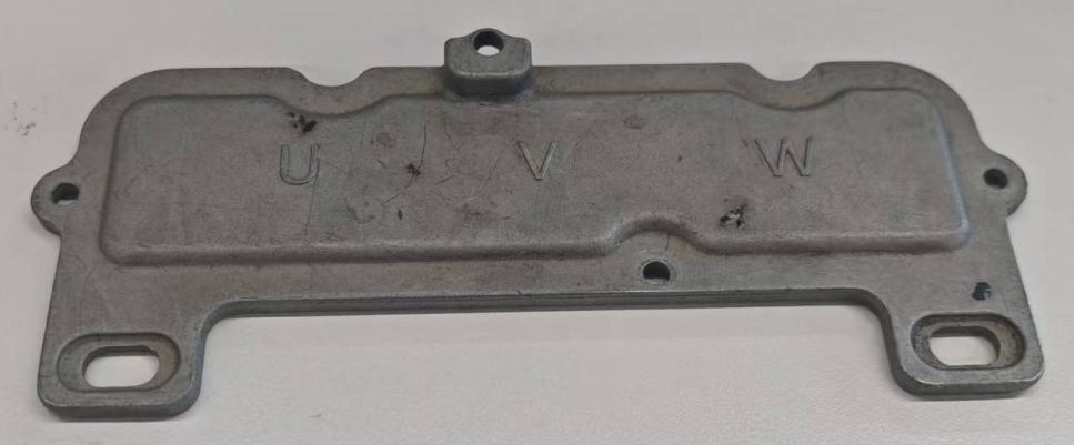
¶ 1. Preparatory work
①Attach 4-5 markers to both front and back surfaces of the workpiece.
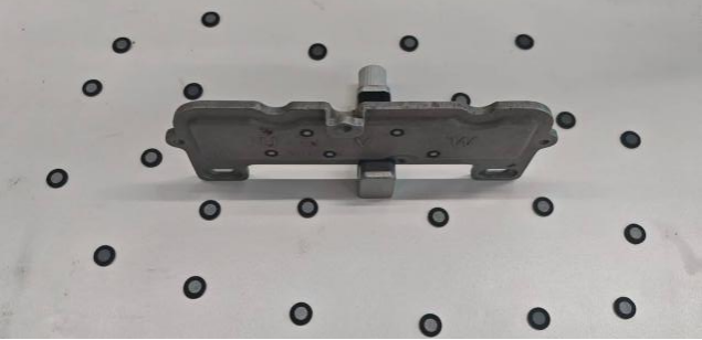
②Place the workpiece vertically on a marker-covered platform (It can be a desktop, a turntable, etc.)
The markers on the platform can assist in capturing the model data on the side.
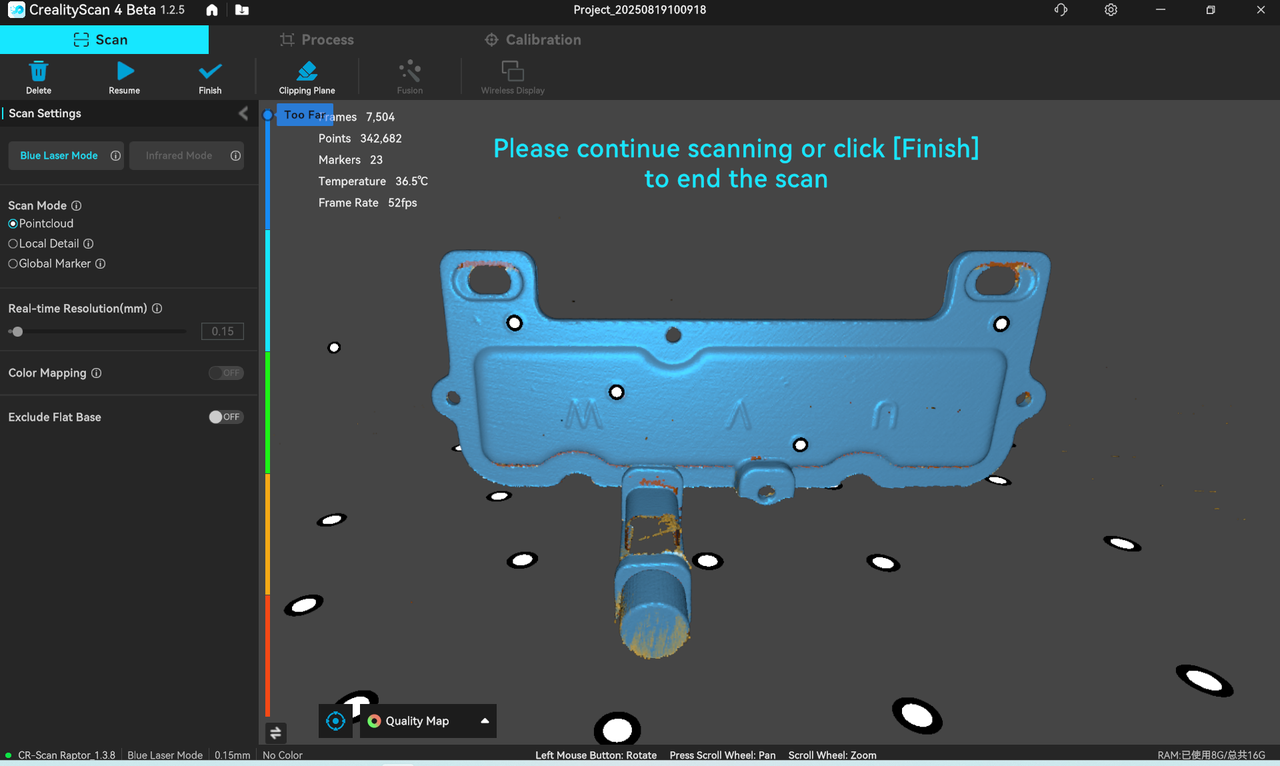
¶ 2. Scan the Complete Model
¶ Method 1: Single Scan (Under One Model File)
Overview: Obtain complete model data by flipping the object over and continuing to scan the bottom workpiece data.
① Scan the workpiece data in its original placement posture, using platform markers to first capture markers on both the front and back sides of the workpiece.
Note: If the workpiece is large, it is recommended to conduct Global Maker scanning first, and then perform point-cloud scanning.
② Pause the scan.Remove or change the auxiliary plane markers, then flip the workpiece: Since the bottom part in contact with the support part cannot be scanned at this stage, pause the scan, delete excess point cloud data on the model, and flip the workpiece to scan the bottom data.
Note: Remove or change the auxiliary plane markers before rescan the scan.
[Reason: The platform markers are used to locate the model data in the first placement posture. If the original platform marker pattern is still used to scan the bottom data after flipping the workpiece, it may cause tracking confusion. Therefore, before rescan the scan, you should remove or change the pattern of auxiliary plane markers: If the markers are pasted on the platform, peel off the markers attached to the platform; If the markers are not adhesive, disrupt the marker pattern; If the markers are attached to a turntable, attach markers to the other side of the turntable and put the object to another side.
③ Resume scanning the bottom data of the workpiece to obtain a complete workpiece model.
¶ Method 2: Scan in Two Sessions and Merge
① Scan the point cloud data of the workpiece in its first standing posture. After scanning, delete excess point cloud data.
②Start a new scan:Place the thin-walled part with its bottom facing upwards and scan the second set of point cloud data. After scanning, delete excess point cloud data.
¶ 3. Postprocessing
According to Method 1, after a single scan, remove the redundant point cloud data --> Point cloud fusion --> Meshing
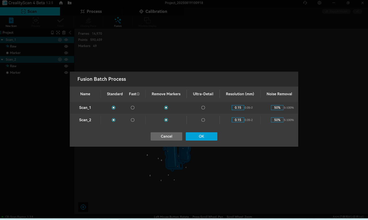
According to Method 2, remove the redundant point cloud data from the two sets --> "Batch point cloud fusion" processing --> Manual alignment --> Meshing, as follows:
①Fusion Batch Process of the 2 sets data
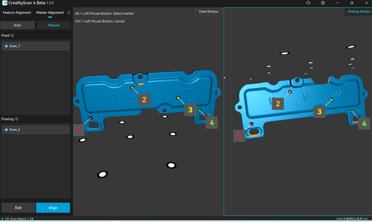
③Generate the final mesh.
¶ Summary:
Scanning of thin-walled parts requires the use of platform maker points.
Scanning thin-walled parts within a single model file results in high accuracy and good data quality, but the platform reference points need to be adjusted to facilitate subsequent scans.While the method of align together after two scans is relatively simple but may leave alignment artifacts if the point cloud edges are poorly captured.
Let me know if further adjustments are needed!