¶ Creality Inspect Beginner's Guide
¶ 1 Software Introduction
Creality Inspect is a 3D inspection software. By comparing a reference model with a scan model, it completes model alignment, deviation inspection, dimensional measurement, geometric tolerance evaluation, template inspection, and inspection report output.
The software includes the following modules:
- Quick Inspection: consolidates frequently used functions so that users can complete an inspection workflow quickly
- Comparison: performs model alignment, deviation analysis, and deviation annotation
- Measurement: creates geometric features, establishes datums and coordinate systems, and performs dimensional measurement and geometric tolerance evaluation
- Report Output: creates report pages, generates reports, and exports inspection reports
- View: adjusts the model viewing direction, display status, and 3D view operations
- Project Management: selects objects, builds groups, and views object properties and inspection results
Typical Use Cases
- Comparing 3D-printed scan data with CAD: view the color-coded distribution of warpage, shrinkage, and forming deviation, and locate excess and shortage areas
- First-article inspection of injection-molded and stamped parts: inspect surface deviation along the mold opening direction or free-form surface direction to evaluate molding quality
- Precision inspection of shaft and disc parts: measure radial dimensions, coaxiality, circular runout, and other geometric tolerances against drawing requirements
- Critical dimension sampling: quickly measure hole positions, slot widths, face spacing, and other critical dimensions, and judge pass/fail automatically against tolerances
- Batch part inspection: save the first inspection workflow as a template, reproduce it for parts of the same type with one click, and output an inspection report with the company logo
If you are using the software for the first time, start with Quick Inspection — it arranges the most commonly used functions in inspection order, and one walkthrough completes a full inspection.
¶ 2 Starting the Software
Register and log in with a Creality account on first use. After logging in, you can create a new inspection project, open an existing project (*.crealityInspect), or continue from a recent project list.
¶ 3 Quick Inspection
The common inspection workflow is as follows:
New Project → Import reference model and scan model → Complete model alignment → Run deviation inspection → Create the required geometric features → Perform dimensional measurement or geometric tolerance evaluation → View inspection results → Generate report → Save project
The Quick Inspection toolbar is divided into the following groups in inspection order:
| Group | Functions | Description |
|---|---|---|
| Import | Import Model | Imports a reference model or scan model |
| Model Alignment | Automatic Alignment, Other Alignments | Automatic Alignment is applied with a single click; other alignment methods are available in the Other Alignments drop-down list |
| Deviation Inspection | Overall Deviation, Cross-Section Deviation, Curve Deviation | Calculates the deviation distribution on the model surface, cross-section, or curve |
| Deviation Annotation | Deviation Annotation | Adds annotations to the color map of Overall, Cross-Section, or Curve Deviation |
| Create Features | Buttons for points, lines, planes, circles, etc. | Creates the geometric features required for inspection |
| Datum and Coordinates | Create Datum, Create Coordinate System | Establishes inspection datums and measurement coordinate systems |
| Basic Measurement | Angle Measurement, Measure Length, Measure Radial Distance | Measures key dimensions of different features |
| Report Output | Create Report Page, Generate Report | Consolidates inspection data and outputs an inspection report |
The functions in Quick Inspection are identical to the functions of the same name in the Comparison and Measurement modules.
¶ 4 Import Model
Import CAD or mesh models as inspection references or scan objects.
Supported models:
| File Type | Supported Formats | Purpose |
|---|---|---|
| CAD model | .igs, .iges, .step, .stp, .brep | Automatically used as the reference model |
| Mesh model | .ply, .stl, .obj, .qobj, .off | Selected by the user as the reference model or scan model |
The reference model represents the design intent or inspection datum of the product; the scan model represents the actual inspected object obtained by scanning.
Operation steps:
- Click Import Model
- Select the model file to import
- Confirm the import
- Wait until the model finishes loading
- Check that the model has been added to the current project
When a CAD model is imported, the software automatically sets it as the reference model.
When a mesh model is imported, the software prompts you to select the purpose of the file:
- Reference Model
- Scan Model
When multiple mesh files are imported at the same time, confirm the purpose of each file separately.
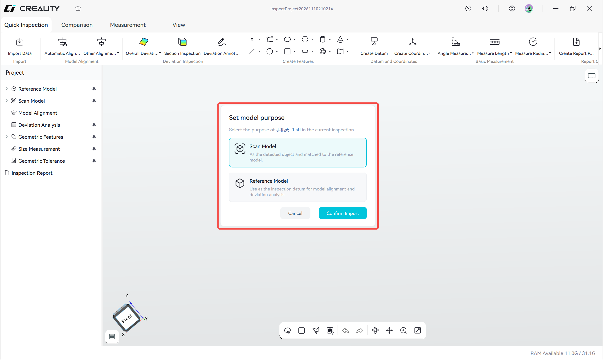
Caption: Figure 4-1 Selecting the file purpose when importing a mesh model
¶ 5 Comparison Module
¶ 5.1 Model Alignment
Model alignment is a prerequisite for model inspection.
- Purpose: the software can extract reference features and calculate the measured deviation only after the scan model is correctly positioned in the coordinate system of the reference model. Alignment is a prerequisite for all inspection operations.
- Composition: every alignment consists of three elements — the reference model, the model to be aligned, and the constraint basis (the points, planes, coordinate systems, or fitting relations used to determine the pose). Alignment methods differ essentially in their constraint basis.
- Levels and hierarchy:
- Coarse alignment: establishes the overall pose and quickly squares up the scan model; it serves as the basis for fine alignment
- Fine alignment: applies constraints based on datums or features on top of coarse alignment, giving higher positioning accuracy
- Hierarchy: fine alignment follows coarse alignment. If the coarse alignment changes, the fine alignment performed under it must be repeated.
General requirements:
- Specify the reference model and scan model during import, and confirm that the units of the two models are consistent
- Alignment changes only the pose, not the model size; the coordinate system of the reference model is fixed and the scan model is registered
- Geometric elements of the reference model can be picked directly; the scan model cannot be picked directly, so points must be constructed by fitting or point selection
Alignment Overview
Alignment Operation Level Constraint Basis Typical Use Core Input
Automatic Alignment Automatic Coarse Global iterative fitting General parts without explicit datum requirements Reference model, scan model, alignment mode
Manual Alignment Manual Coarse Feature points When automatic alignment performs poorly 3 manually matched point pairs
RPS Alignment Manual Fine Non-solid features (projected) Coarse alignment completed, high accuracy required 3 projected feature pairs
3-2-1 Alignment Manual Fine Coordinate system from three planes, 6 points in total Parts with clear three-axis datum planes 6 points
Coordinate System Alignment Manual Fine Local coordinate systems of both models Coordinate systems already built by the same rule Local coordinate systems
Datum Alignment Manual Fine Corresponding constructed geometry Evaluation per drawing datums, degrees of freedom must be controlled 3 corresponding constructed geometry pairs
Local Alignment Manual Fine Local region fitting Globally correct, locally out of tolerance At least 1 feature region
5.1.1 Coarse Alignment
If the inspection accuracy requirement is not high, subsequent inspection can be performed directly after coarse alignment; if high accuracy is required, perform fine alignment after coarse alignment.
Coarse alignment establishes the initial alignment of the models. The software provides two methods, Automatic Alignment and Manual Alignment, and both can serve as the starting point for fine alignment.
5.1.1.1 Automatic Alignment
Automatic Alignment is the recommended coarse alignment method for the first inspection.
- Typical use: general parts without explicit datum requirements, where the overall pose must be established quickly.
- Constraint basis: the software automatically solves and adjusts the pose of the scan model so that it coincides with the reference model.
- Inputs: reference model, scan model, alignment mode.
Steps:
- Click Automatic Alignment;
- Select the reference model and the scan model;
- Select the alignment mode. Standard mode is selected by default; switch to High Precision mode if a more accurate automatic alignment is required;
- Click Create.
Alignment mode: use Standard mode when the model surface has clear structure; use High Precision mode when the surface structure is indistinct or flat. For rotationally symmetric parts, High Precision mode or Manual Alignment is recommended.
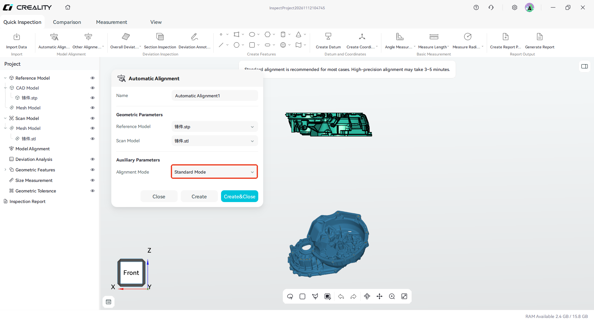
Caption: Figure 5-1-1 Import the models and confirm the alignment accuracy
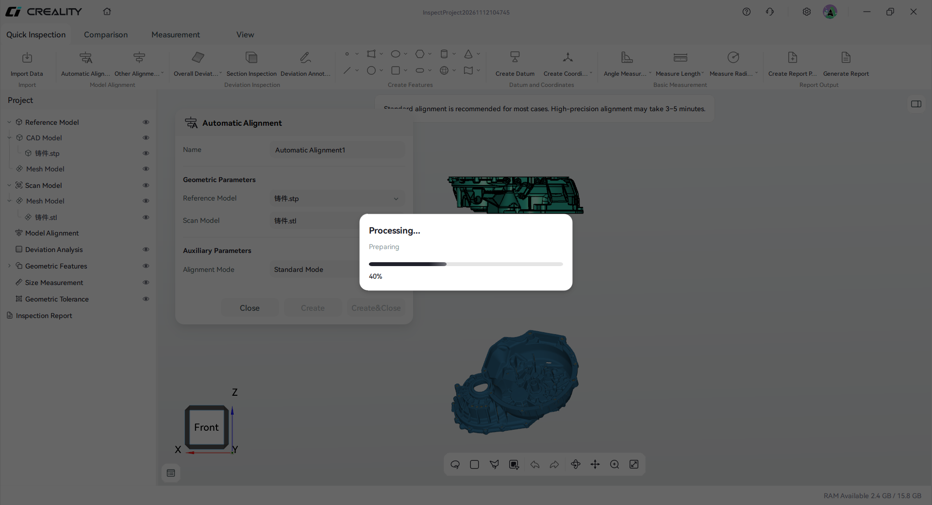
Caption: Figure 5-1-2 Wait for the alignment to complete
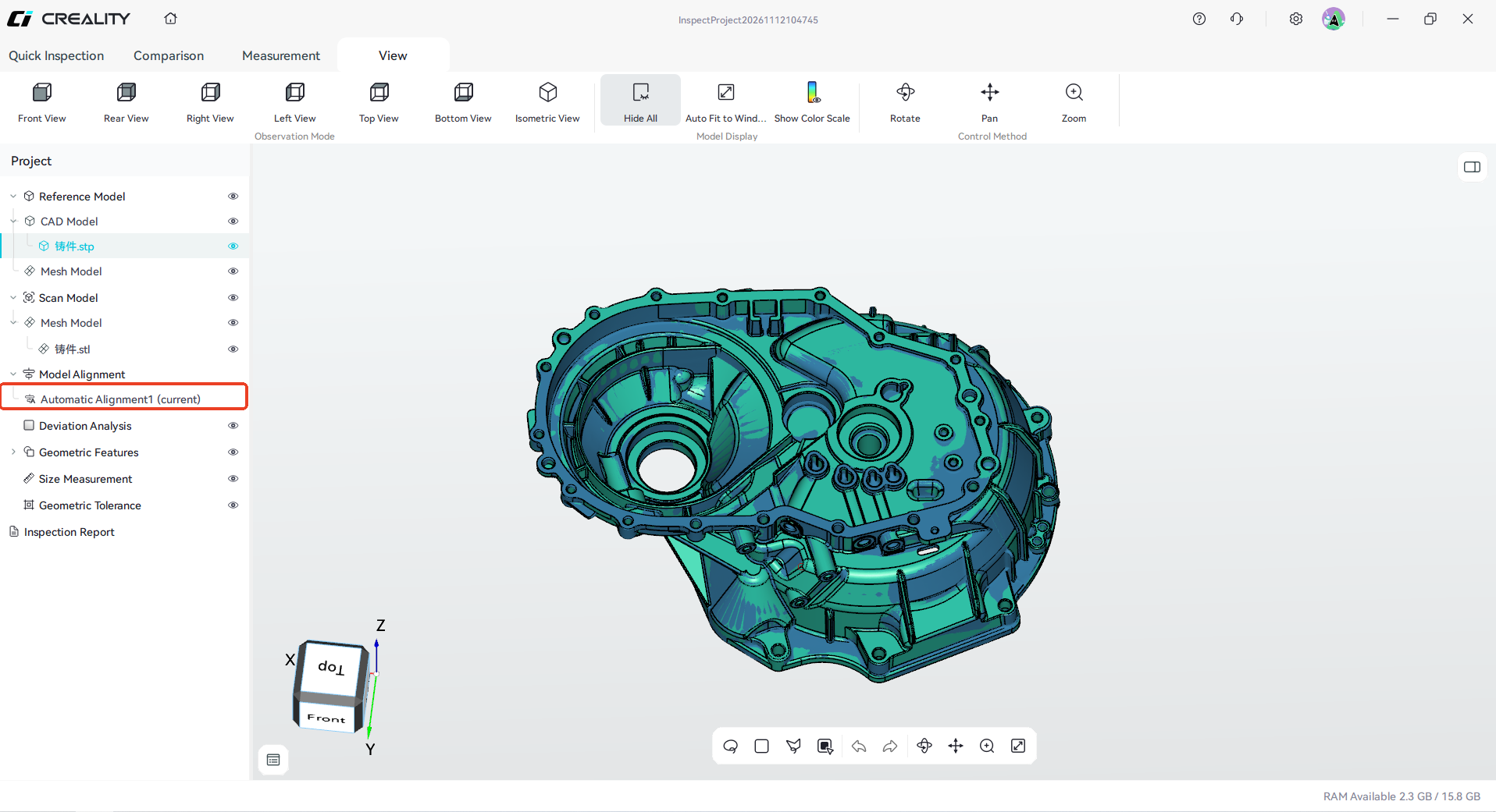
Caption: Figure 5-1-3 Automatic alignment completed
5.1.1.2 Manual Alignment
Manual Alignment is a coarse alignment method performed manually when automatic alignment performs poorly.
- Typical use: when automatic alignment performs poorly, or when corresponding positions must be specified.
- Constraint basis: 3 matched point pairs.
- Inputs: reference model, scan model, 3 manually selected point features.
Steps:
- Click Manual Alignment;
- Pick 3 feature points on the reference model;
- On the scan model, select the 3 corresponding feature points at positions close to or identical with those on the reference model, in the same order as they were picked on the reference model;
- Click Create.
Feature point requirements: the three feature points on the same model must not be collinear and should be spread as far apart as possible. Prefer corners, hole positions, bosses, and other clearly defined structures.
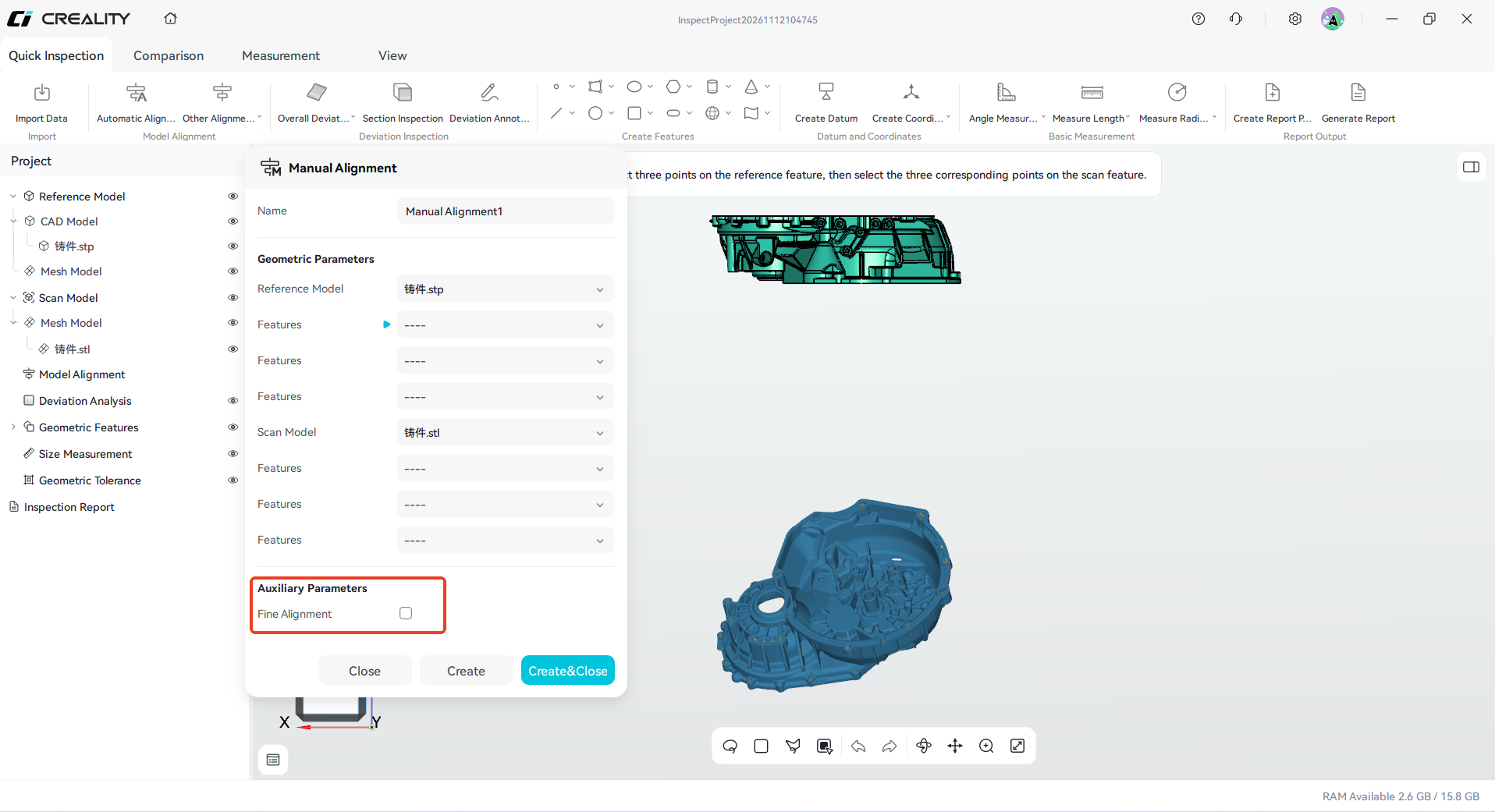
Caption: Figure 5-1-4 Import the models and confirm the alignment accuracy
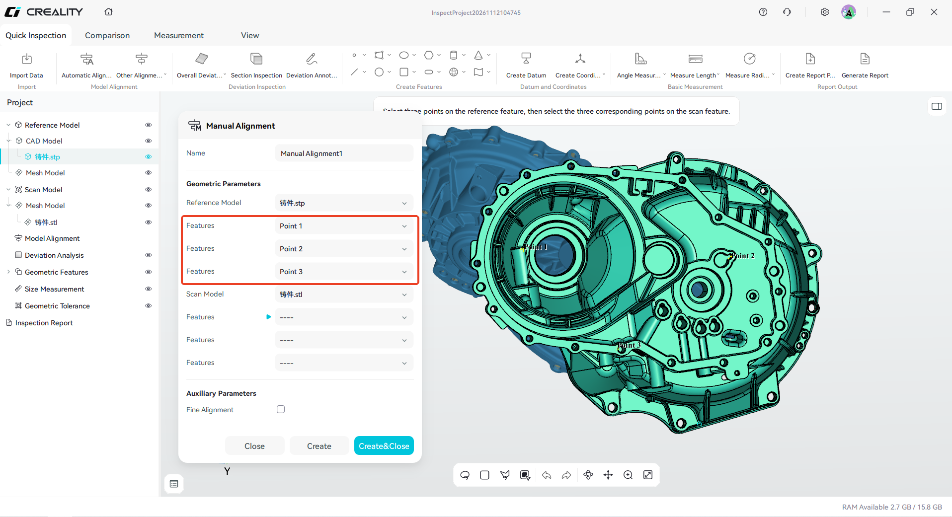
Caption: Figure 5-1-5 Manually pick points on the reference model
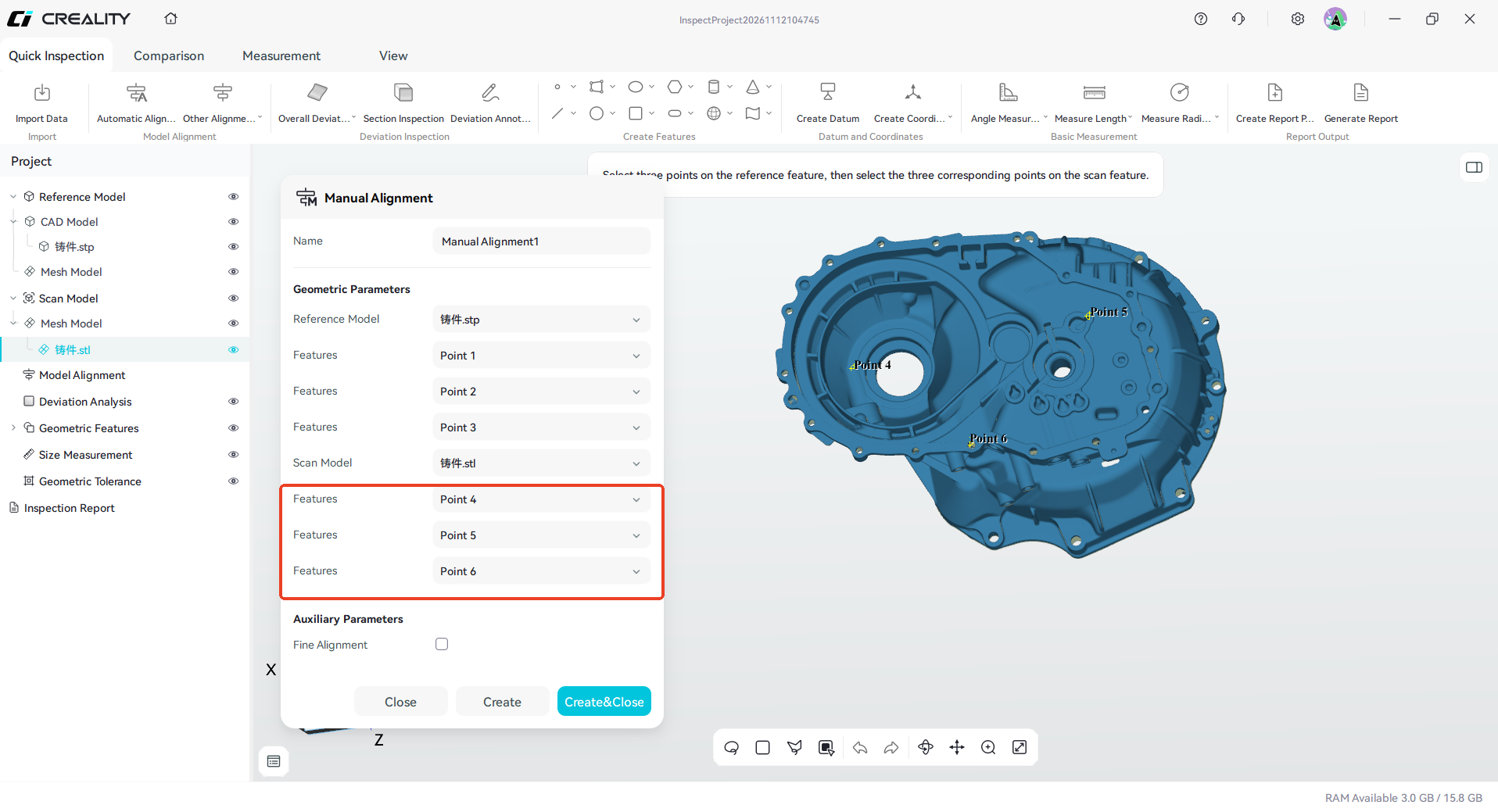
Caption: Figure 5-1-6 Manually select points on the scan model
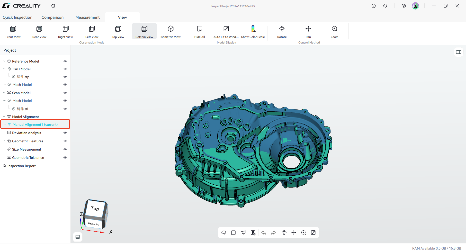
Caption: Figure 5-1-7 Manual alignment completed
5.1.2 Fine Alignment
Fine alignment applies constraints on top of coarse alignment to perform a second alignment; the result is used for formal comparison and evaluation. The software provides five methods, distinguished by their constraint basis.
5.1.2.1 RPS Alignment
RPS Alignment is used when specified holes, planes, and other geometric features have inspection accuracy requirements.
- Typical use: parts that have completed coarse alignment and require features with projection relations to further improve alignment accuracy.
- Constraint basis: at least 3 feature pairs with projection relations.
- Prerequisites: coarse alignment is complete; both models already have at least 3 pairs of identical features with projection relations (for example, three circles or three points). The projection can be created by Associated Projection or Best-Fit Projection.
Steps:
- Click RPS Alignment;
- On the reference model, select at least three groups of geometric features that have projection relations;
- Click Create.
Note: RPS Alignment uses features with projection relations to constrain the alignment pose. If the projection relations are not established as required, this alignment method cannot be executed.
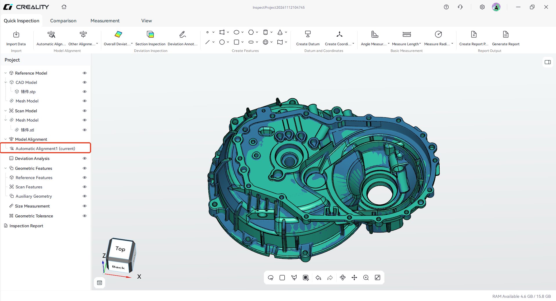
Caption: Figure 5-1-8 Confirm that coarse alignment is complete
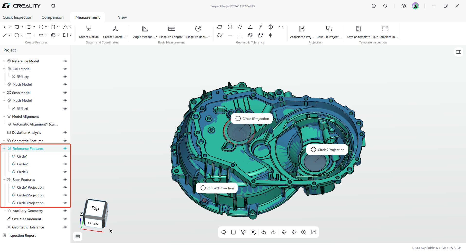
Caption: Figure 5-1-9 Confirm that the reference and scan models have at least three groups of geometric features with projection relations
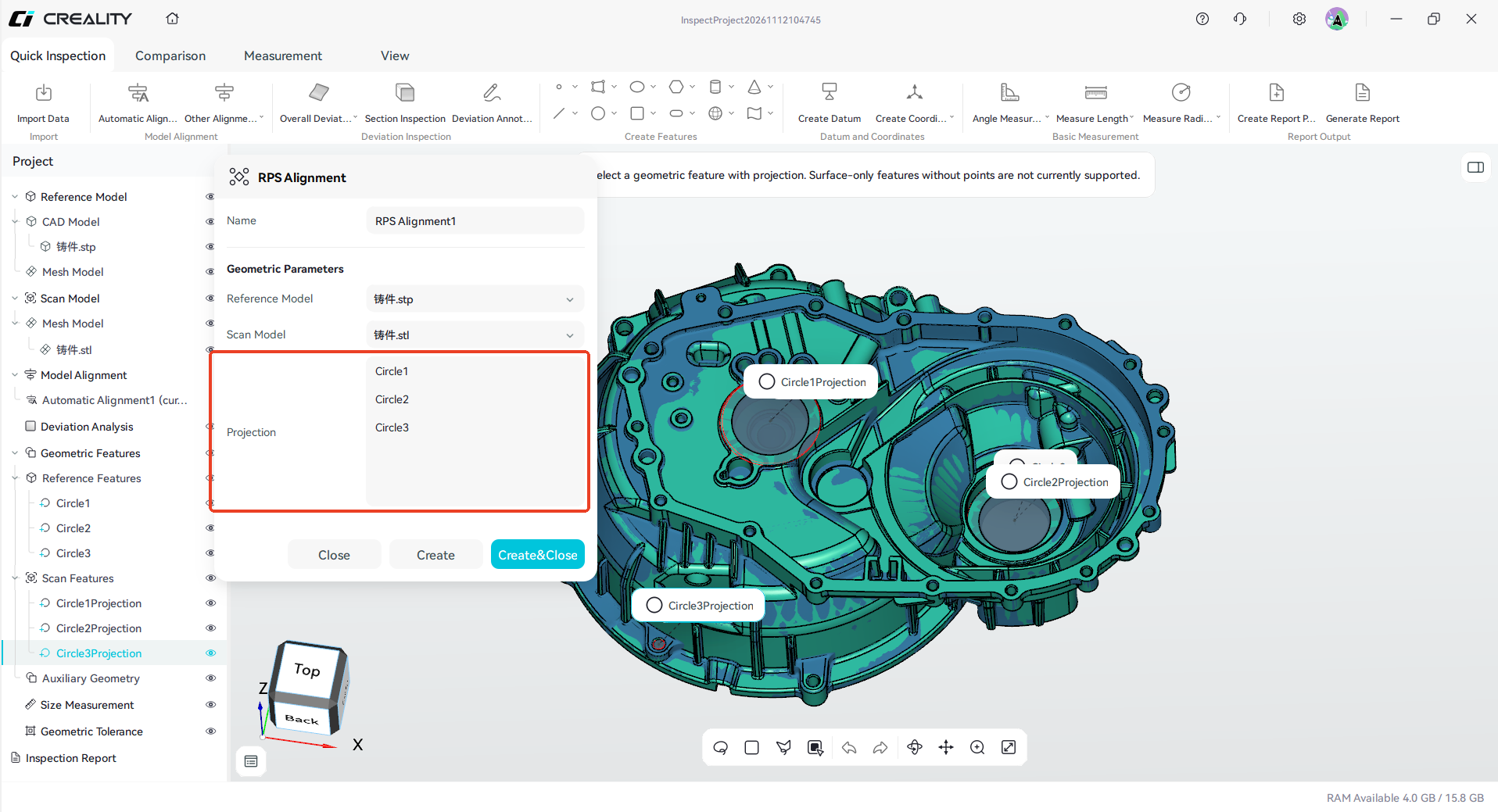
Caption: Figure 5-1-10 Select the geometric features with projection relations in the 3D view
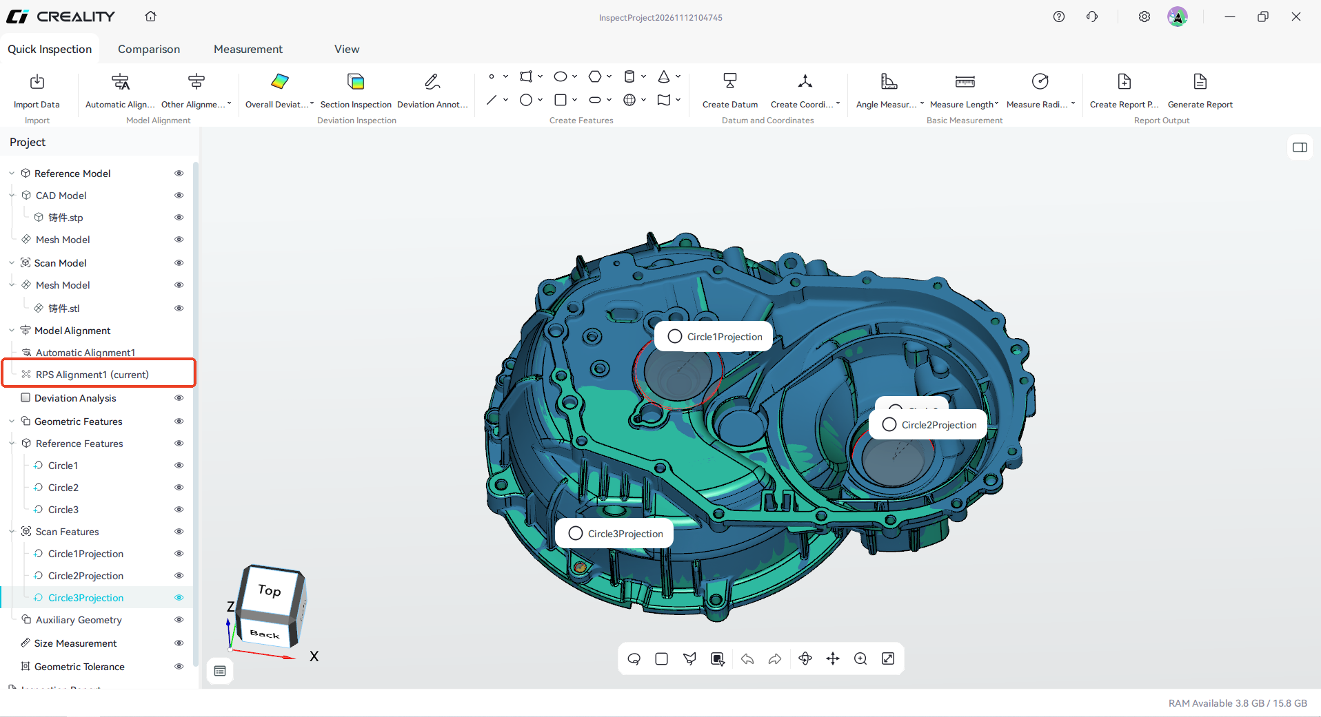
Caption: Figure 5-1-11 RPS alignment completed
5.1.2.2 3-2-1 Alignment
3-2-1 Alignment aligns the scan model to a specified coordinate system and is used when the inspection requires a specified coordinate system.
- Typical use: parts with clear three-axis datum planes.
- Constraint basis: the 6 locating points selected in 3-2-1 order (three points define the primary plane, two points define the direction, and one point defines the origin).
Steps:
- Determine the coordinate system position of the reference model, or obtain the alignment coordinate system requirement from the CAD drawing;
- Click 3-2-1 Alignment;
- Select the scan model, and in the 3D view select six points on the scan model to build the alignment coordinate system;
- Select the coordinate system construction method: 6 methods are supported, including ZZZ-YY-X, ZZZ-XX-Y, and YYY-ZZ-X. The method depends on the inspection datum coordinate system;
- Select the spatial points. Taking ZZZ-YY-X as an example, first select or construct three points in the 3D view to define the Z constraint, then select or construct two points to define the Y constraint, and finally define the origin with one point;
- Preview and confirm: after the spatial points are selected, preview the constructed coordinate system in the 3D view and confirm that it matches the coordinate system position of the reference model. The commands Reverse Plane and Reverse Line can be used to correct the positive direction of each axis;
- After confirming the coordinate system position, click Create.
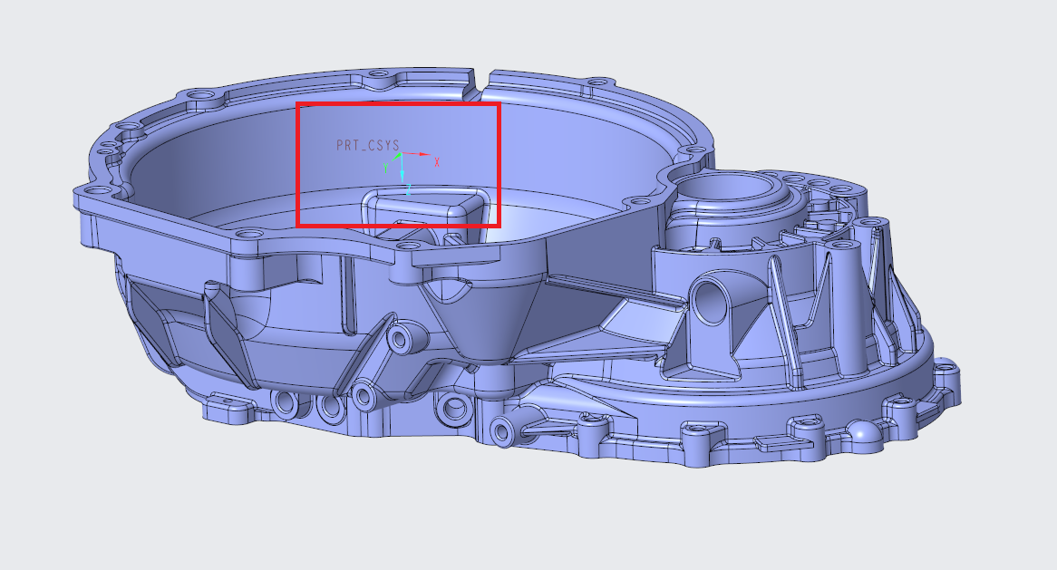
Caption: Figure 5-1-12 Confirm the coordinate system of the reference model in the 3D model
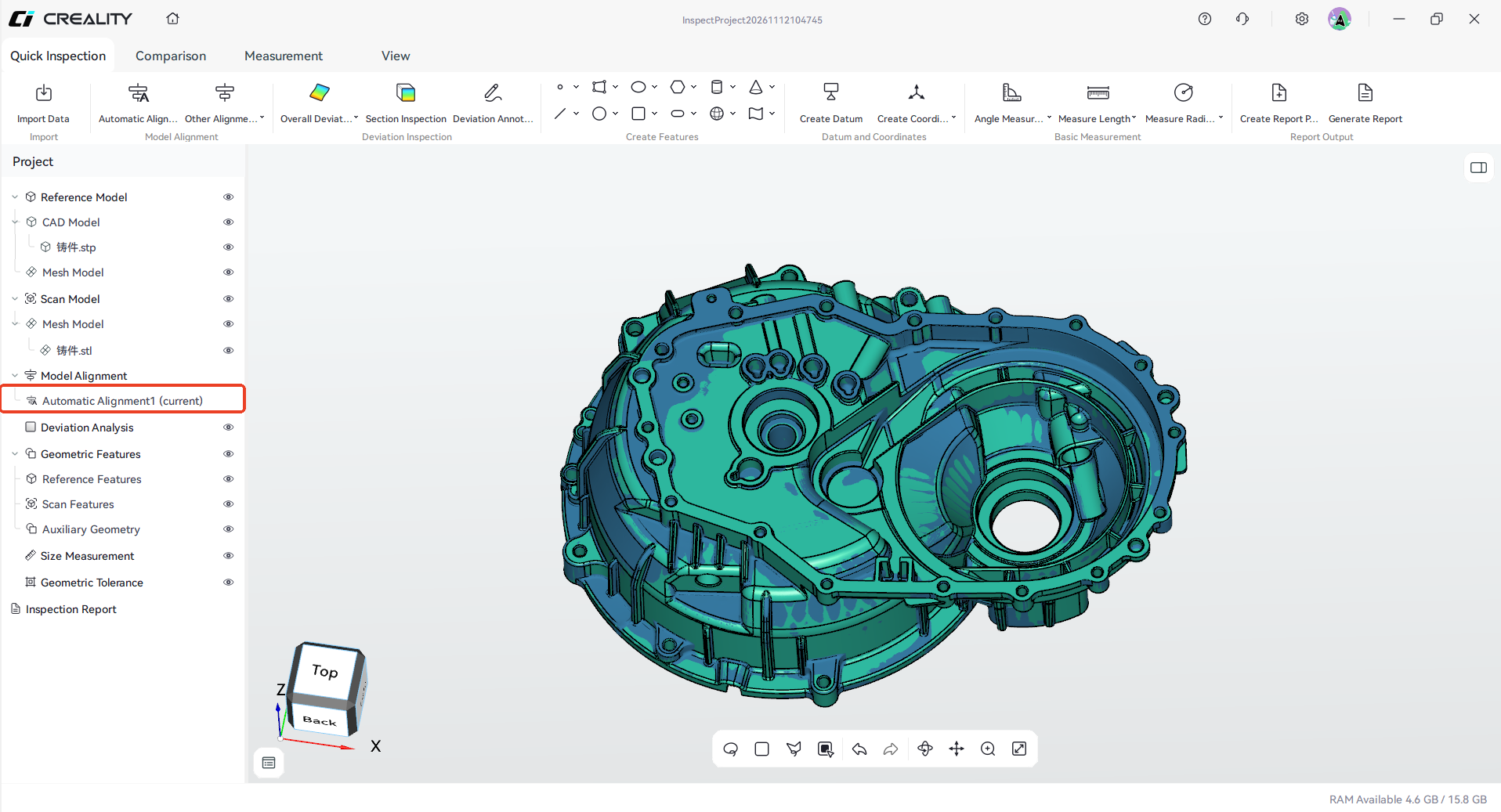
Caption: Figure 5-1-13 Confirm that coarse alignment is complete
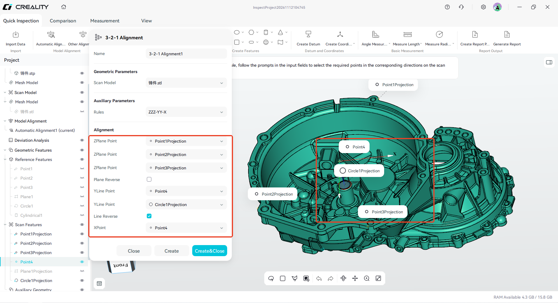
Caption: Figure 5-1-14 Select or construct points on the scan model and preview the coordinate system position
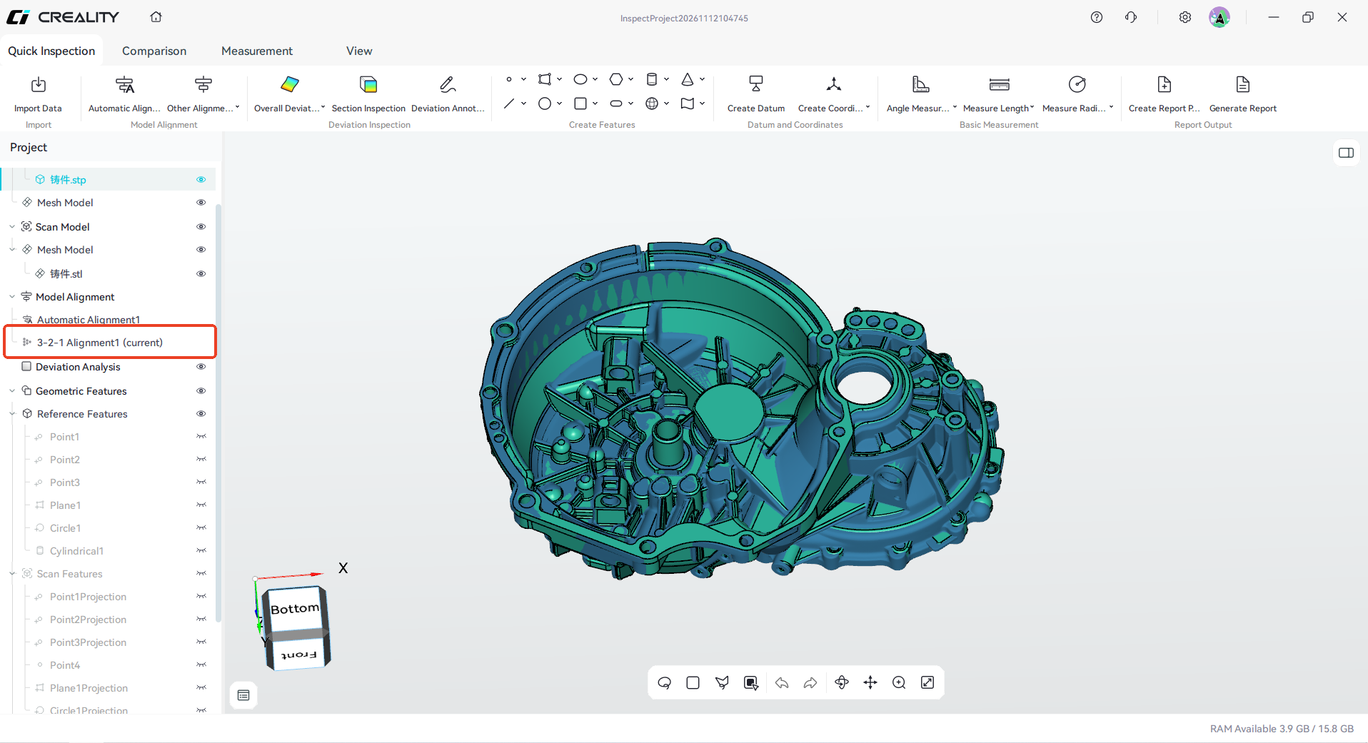
Caption: Figure 5-1-15 3-2-1 alignment completed
5.1.2.3 Coordinate System Alignment
Coordinate System Alignment is a fine alignment method that uses the local coordinate systems of the reference model and the scan model as alignment constraints.
- Typical use: parts whose local coordinate systems have been built on each model according to the same rule.
- Constraint basis: the local coordinate system of each model.
- Prerequisites: both models have the required point, line, and plane features constructed by the same rule, and local coordinate systems have been created.
Steps:
- Click Coordinate System Alignment;
- Select both models and their coordinate systems;
- Click Create.
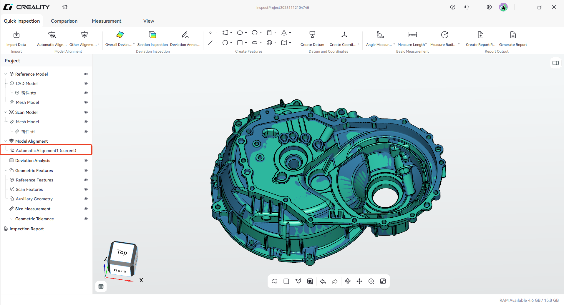
Caption: Figure 5-1-16 Confirm that coarse alignment is complete
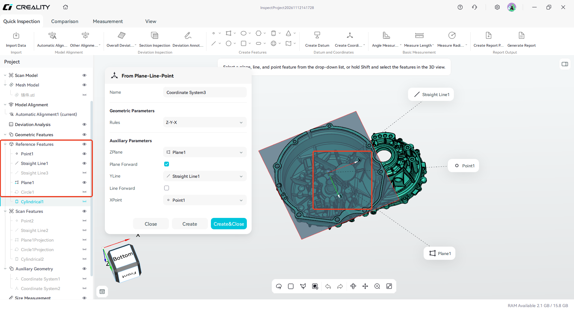
Caption: Figure 5-1-17 Create a coordinate system in the specified region of the reference model
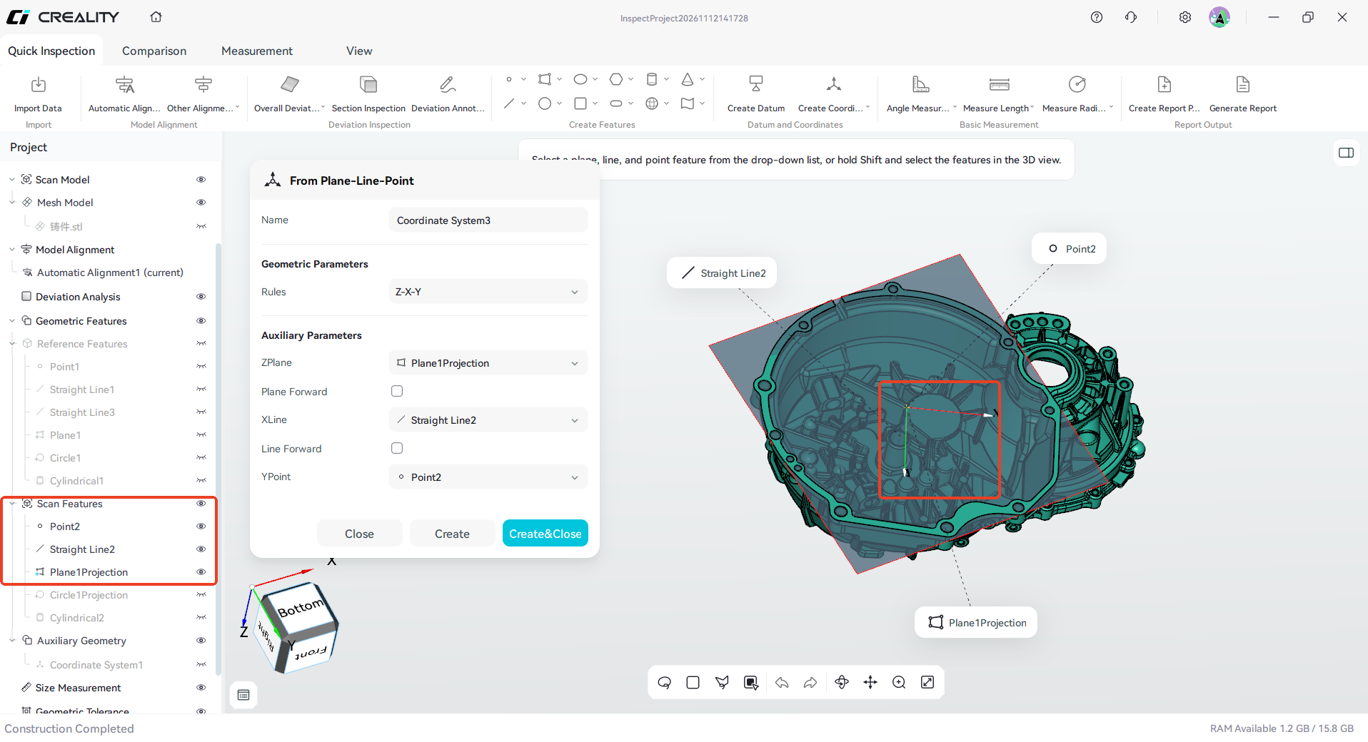
Caption: Figure 5-1-18 Create the corresponding coordinate system in the same region of the scan model
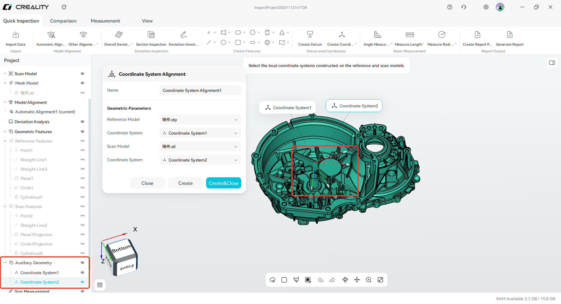
Caption: Figure 5-1-19 Select the two coordinate systems to complete coordinate system alignment
5.1.2.4 Datum Alignment
Datum Alignment is a fine alignment method that uses corresponding geometric features on the reference model and the scan model to constrain degrees of freedom.
- Typical use: parts evaluated against drawing datums, parts whose degrees of freedom must be controlled, or parts that require geometric tolerance output.
- Constraint basis: corresponding constructed geometry on both models.
- Prerequisites: both models have 3 features at the same position and of the same type (for example, three perpendicular planes; two perpendicular lines or cylinders; three points or three circles).
Steps:
- Click Datum Alignment;
- Select both models;
- Select 3 groups of identical features on each model, and set the direction to reverse if necessary;
- When the remaining degrees of freedom reach 0, click Create.
Calculation mode: select Geometry to generate a standard alignment, or GD&T to generate an alignment associated with geometric tolerances.
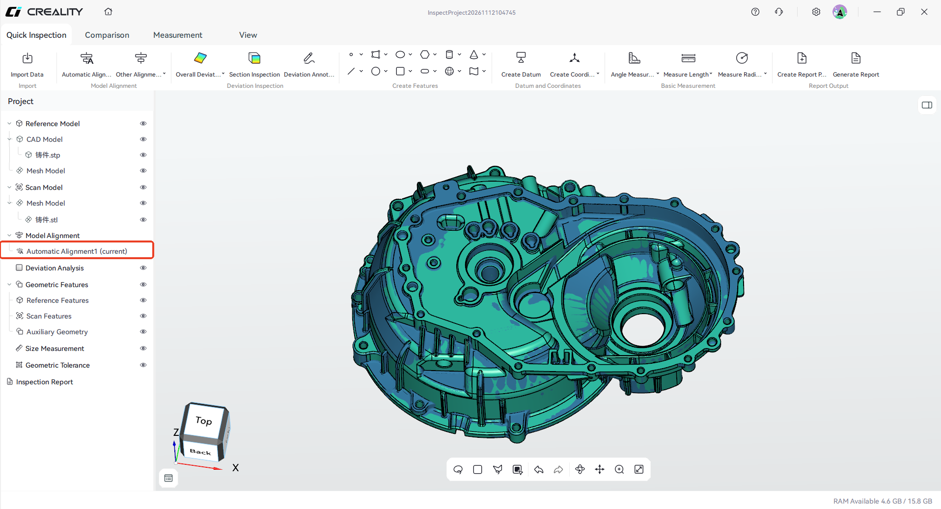
Caption: Figure 5-1-20 Confirm that coarse alignment is complete
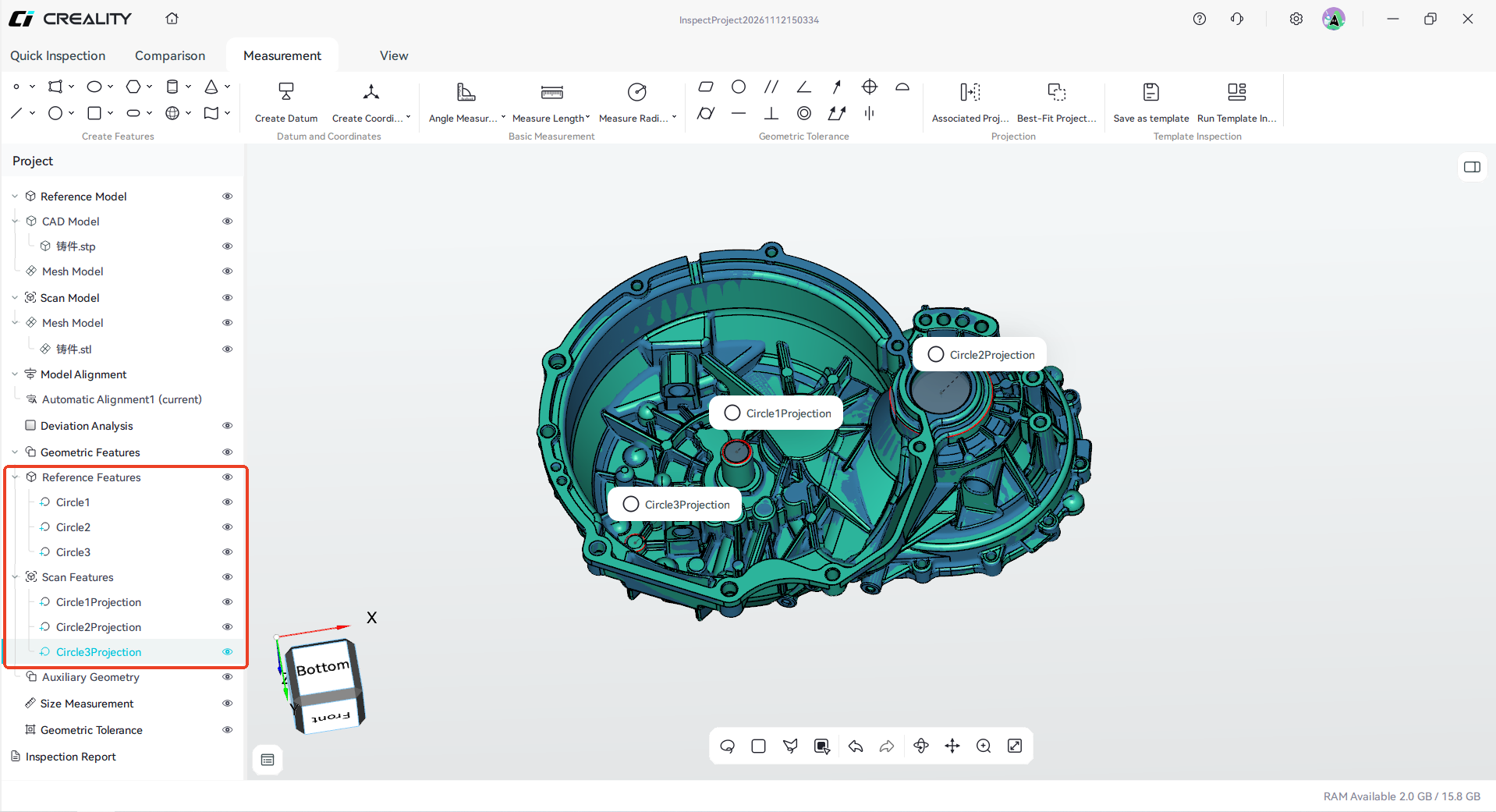
Caption: Figure 5-1-21 Construct 3 identical feature pairs on both models
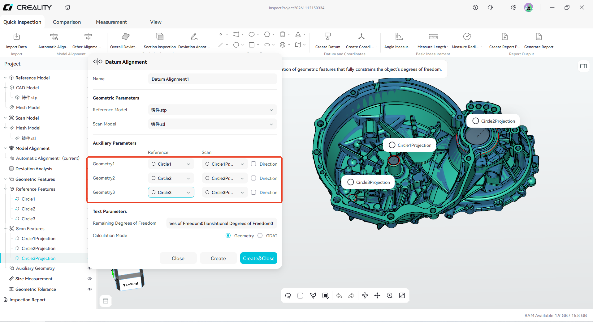
Caption: Figure 5-1-22 Select the existing three feature groups
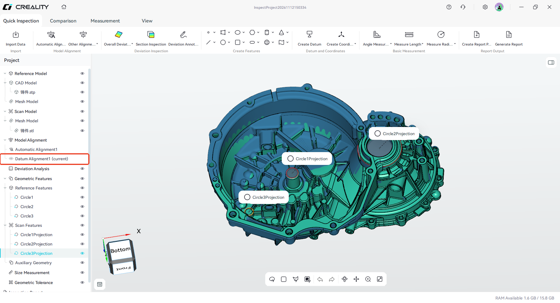
Caption: Figure 5-1-23 Datum alignment completed
5.1.2.5 Local Alignment
Local Alignment is a fine alignment method that focuses on optimizing the alignment of a local region.
- Typical use: parts that are positioned correctly overall but are locally out of tolerance, or where the local alignment result is unsatisfactory.
- Constraint basis: fitting of a local mesh region to the corresponding CAD region.
- Prerequisites: coarse alignment is complete.
Steps:
- Click Local Alignment;
- Select the reference model;
- Use the lasso or rectangle to pick at least 1 feature region on the mesh;
- Click Create.
Note: Local Alignment is calculated only within the selected region. It removes the influence of the overall positioning and evaluates the local deviation separately.
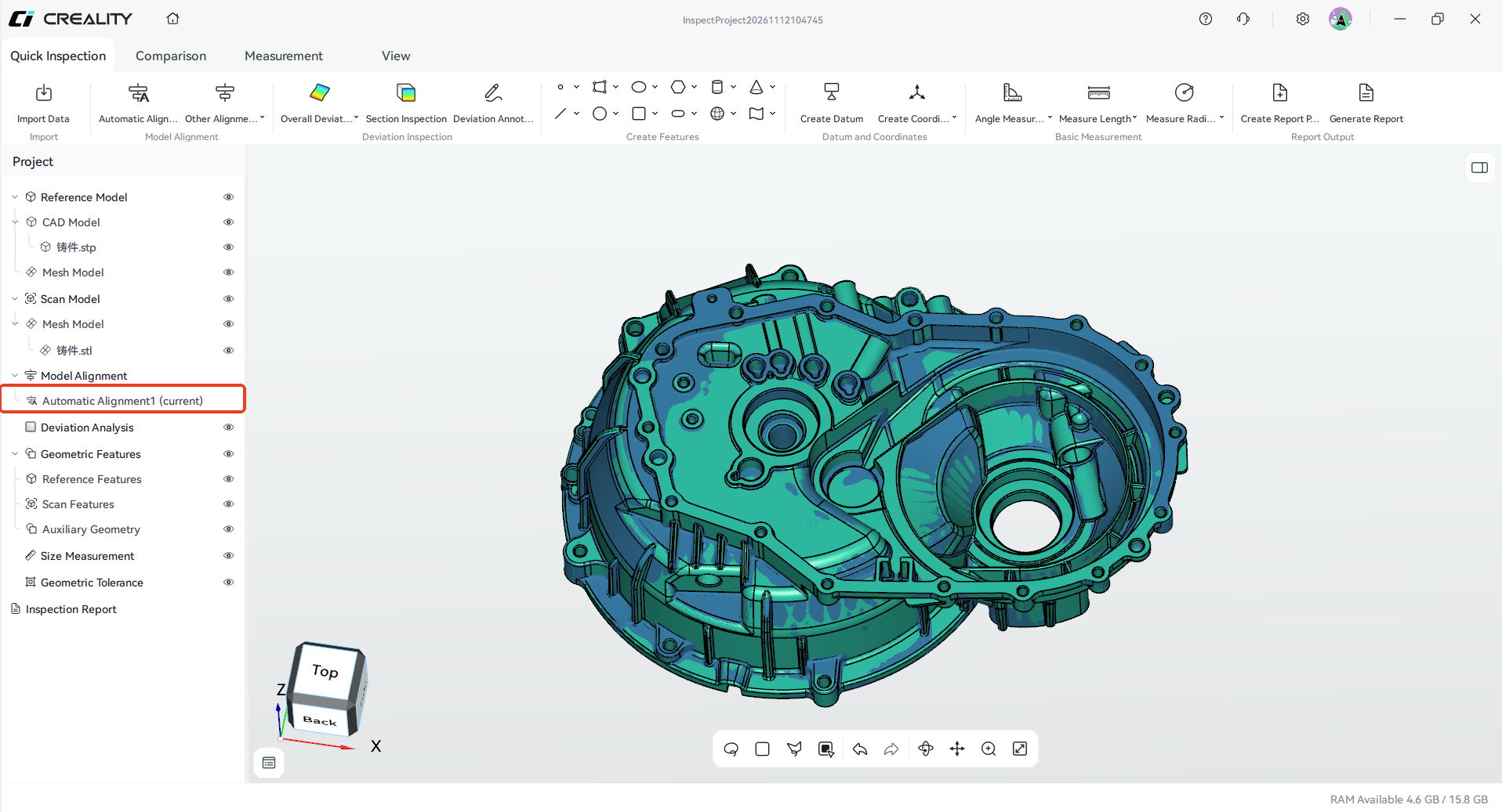
Caption: Figure 5-1-24 Confirm that coarse alignment is complete
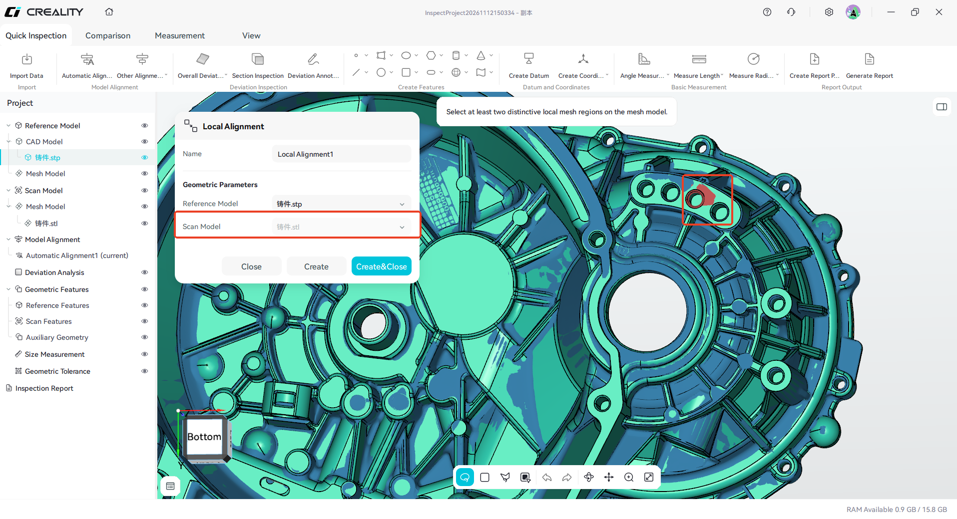
Caption: Figure 5-1-25 Select the local mesh region to be aligned on the scan model
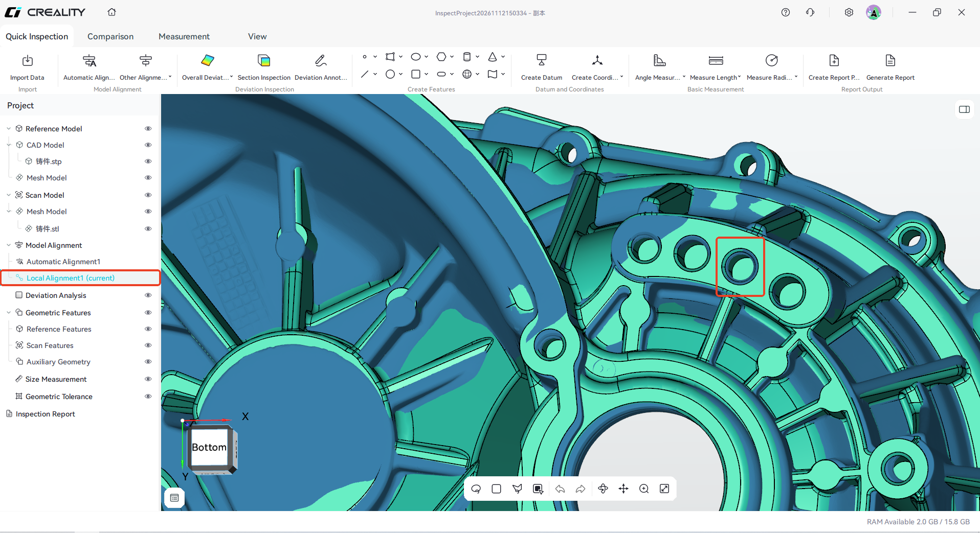
Caption: Figure 5-1-26 Fit of the selected region after local alignment
¶ 5.2 Deviation Inspection
Compare the reference model with the scan model to obtain the deviation distribution on the model surface, cross-section, or curve, and determine whether the part is out of tolerance.
Common prerequisites for all inspections in this chapter: the reference model and scan model have been imported and model alignment has been completed. Alignment accuracy directly affects the deviation values; if the alignment deviation is large, the calculation result is not meaningful.
Reading the results:
- The deviation value is the offset of the scanned surface relative to the reference surface; the positive and negative directions follow the color scale
- Colors correspond to deviation value ranges; the parts beyond the upper and lower tolerance limits are displayed in the out-of-tolerance color
- Pass/fail is judged by the specified tolerance upper limit and tolerance lower limit
- Different calculation methods use different value definitions; the same method should be used for the same batch of parts
5.2.1 Overall Deviation
Compares the surface difference between the reference model and the scan model and generates a color-coded deviation map
The software provides two deviation calculation methods:
- Shortest Distance Method: calculates the shortest distance from each point on the scan model to the reference model surface as the deviation value of that point. It does not depend on a specific direction and is suitable for free-form surfaces or cases without an explicit inspection direction; it is the most commonly used method
- Specified Direction Method: calculates the deviation along a specified direction (such as the X/Y/Z axis or a custom vector). It is suitable for cases with an explicit inspection direction, for example inspecting the surface deviation of stamped or injection-molded parts along the mold opening direction
Operation steps:
- Complete model alignment
- Click Overall Deviation
- Select the calculation method: Shortest Distance Method or Specified Direction Method
- Select the reference model and the scan model
- Set the color scale range, tolerance upper limit, and tolerance lower limit
- Run the calculation
- View the deviation distribution and the color scale
The deviation result depends on alignment accuracy. If the distribution is clearly abnormal, check the alignment result first.
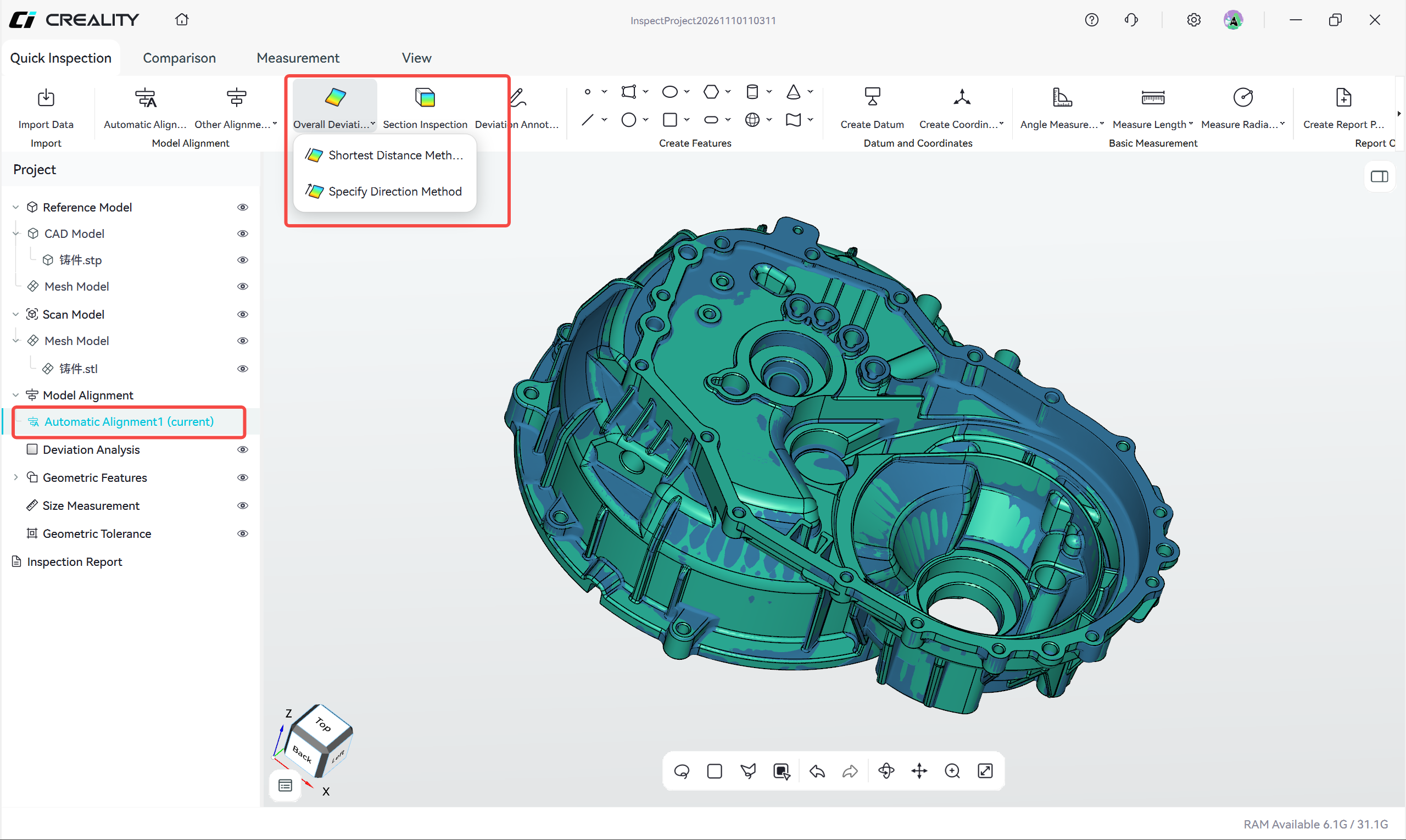
Caption: Figure 5-2-1 Calculate overall deviation based on the alignment result
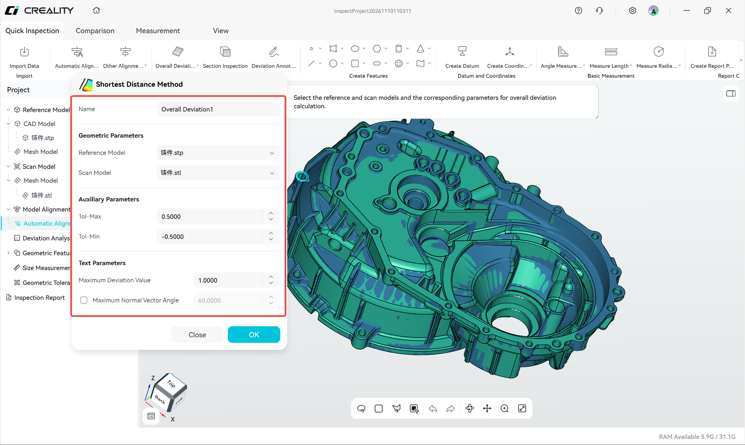
Caption: Figure 5-2-2 Select the Shortest Distance Method
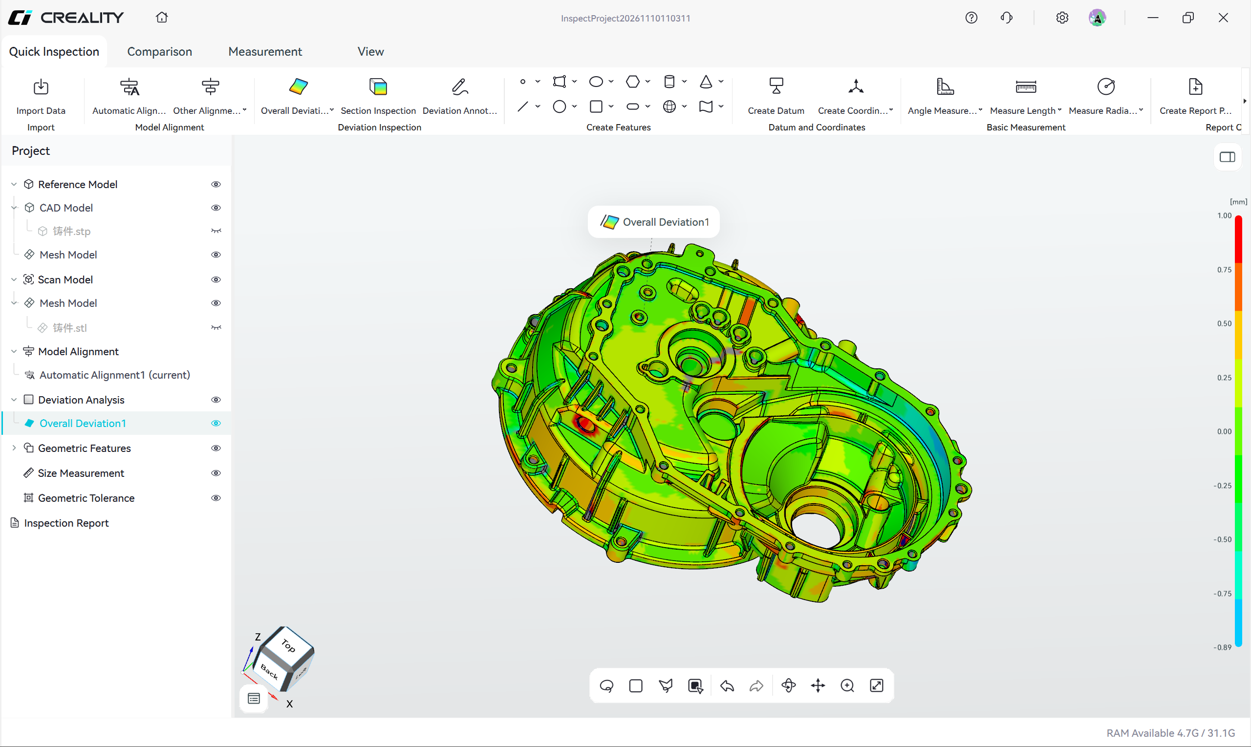
Caption: Figure 5-2-3 Overall deviation result
5.2.2 Cross-Section Deviation
Compares the profile difference between two models on a specified cross-section
Before use, complete model alignment and create the plane feature used for the cross-section in advance.
Operation steps:
- Complete model alignment
- Create the plane feature required for the cross-section
- Click Cross-Section Deviation
- Select the reference model and the scan model
- Select the plane feature as the cross-section
- Run the deviation calculation
- View the cross-section profile and deviation result
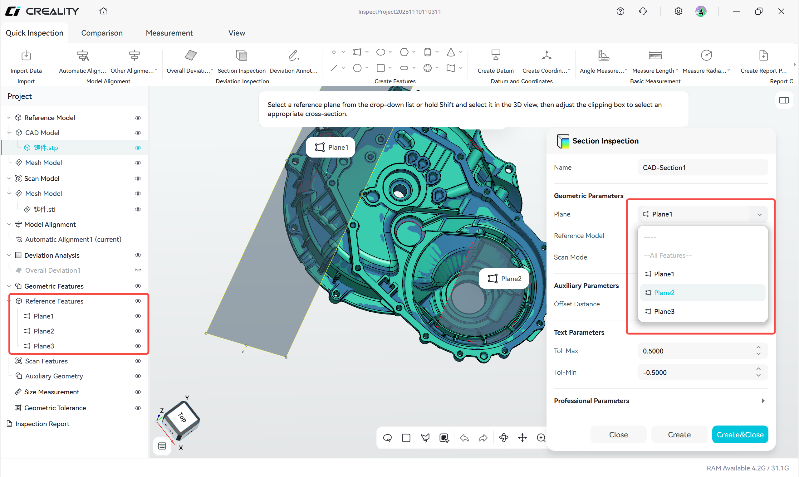
Caption: Figure 5-2-4 Select the cross-section plane feature
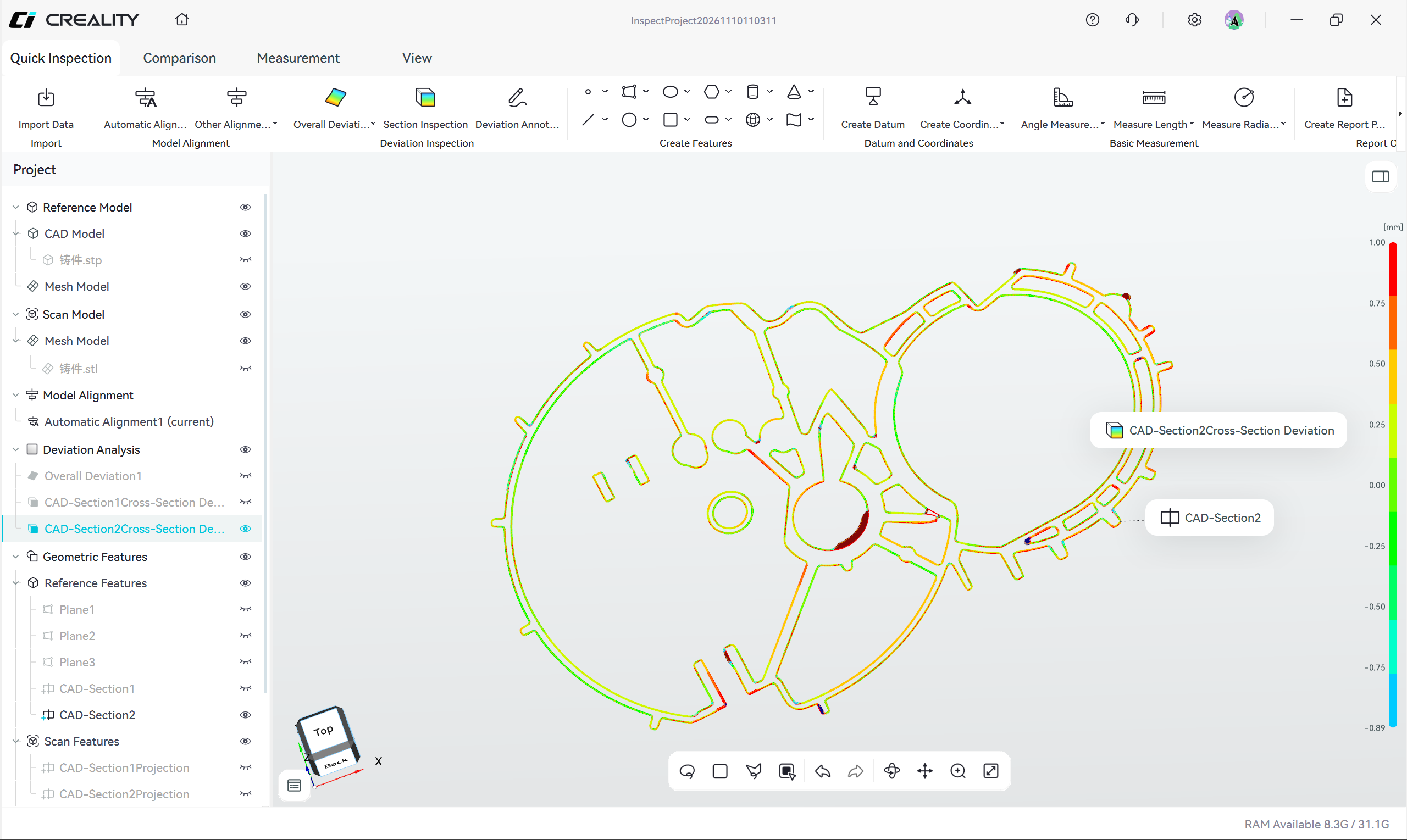
Caption: Figure 5-2-5 Cross-section deviation result
5.2.3 Curve Deviation
Compares the shape difference between the reference curve and the corresponding curve on the scan model
Before use, complete model alignment and construct the reference curve in advance.
Operation steps:
- Complete model alignment
- Construct the reference curve
- Click Curve Deviation
- Select the reference curve and the corresponding curve on the scan model
- Set the deviation range and tolerance
- Run the calculation
- View the curve deviation result
Tip: when constructing the reference curve, hold Shift and use the point picking mode in the 3D view to select points on the CAD model.
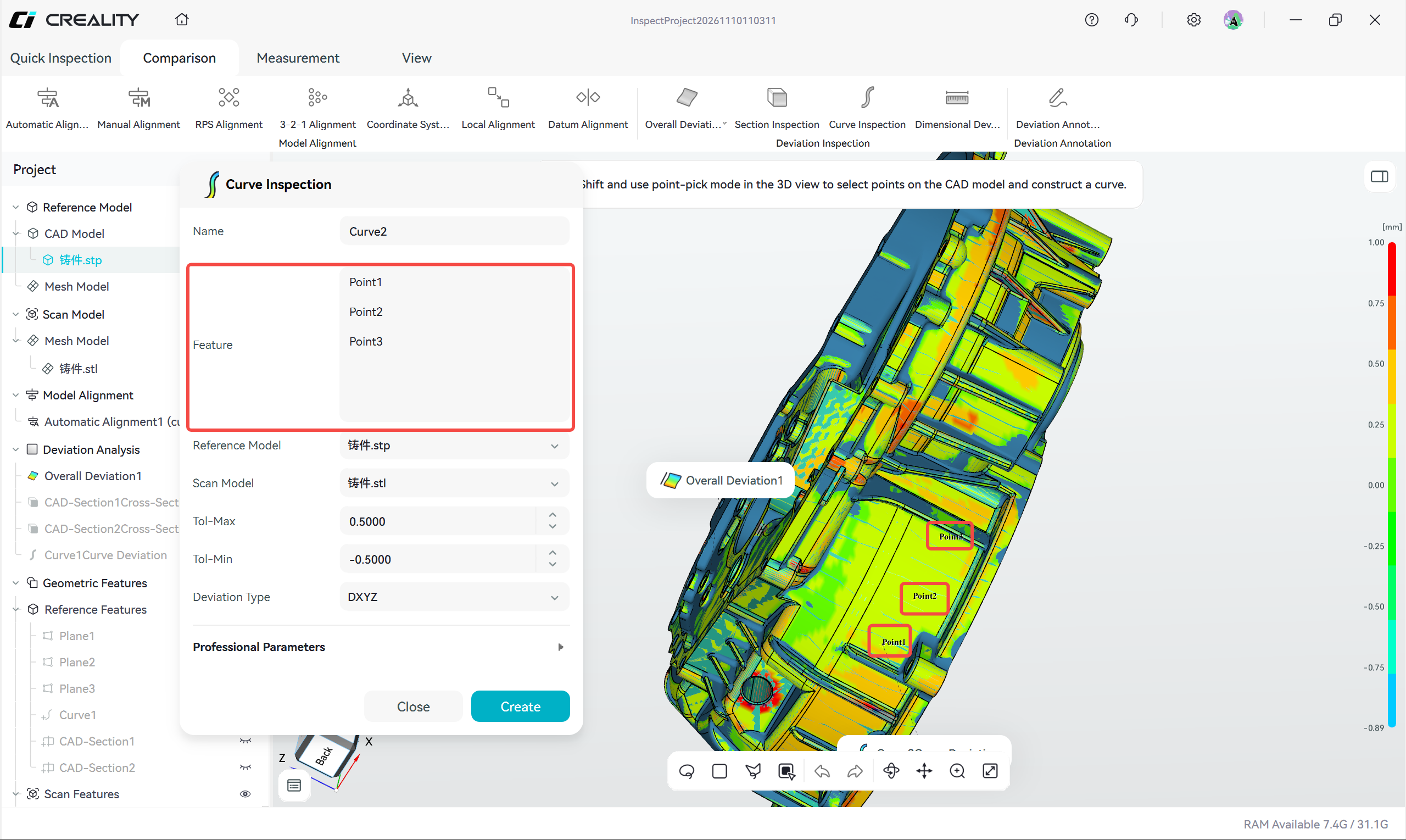
Caption: Figure 5-2-6 Construct the reference curve
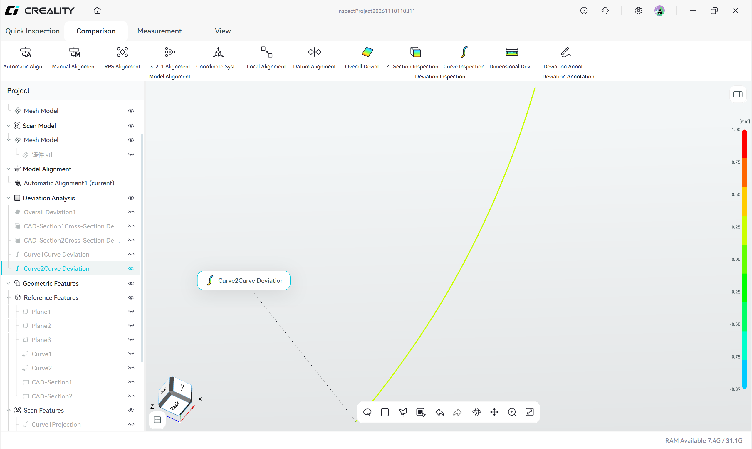
Caption: Figure 5-2-7 Curve deviation result
5.2.4 Dimensional Deviation
Compares the size, position, or orientation difference of associated features and judges pass/fail
Dimensional Deviation evaluates a pair of associated features: a reference feature on the reference model and a scan feature on the scan model. The association can be established by Best-Fit Projection or Associated Projection; the difference is whether the scan feature is generated by the software or created by the user.
Method 1: Best-Fit Projection (CAD feature first, scan feature fitted by the software)
Only the reference model needs a feature; the corresponding feature on the scan model is fitted automatically by the software.
Typical use: the reference model is a CAD model, the scan data is complete, and manual modeling should be minimized.
Operation steps:
- Complete model alignment
- Create the reference feature on the reference model in CAD mode (point, line, plane, etc.)
- Click Best-Fit Projection
- Select the reference feature
- Select the scan model
- Select Use fixed distance and set the distance value as needed, or adjust Maximum Normal Vector Angle
- Run the fitting; the software automatically generates the corresponding feature on the scan model
- Check the fitting result and confirm that the position and shape of the scan feature are as expected
- Click Dimensional Deviation
- Select the associated features to compare
- Set the tolerance
- Run the calculation and view the nominal value, actual value, deviation, and pass/fail status
If the fitting result is unsatisfactory, adjust the parameters above and fit again before running Dimensional Deviation.
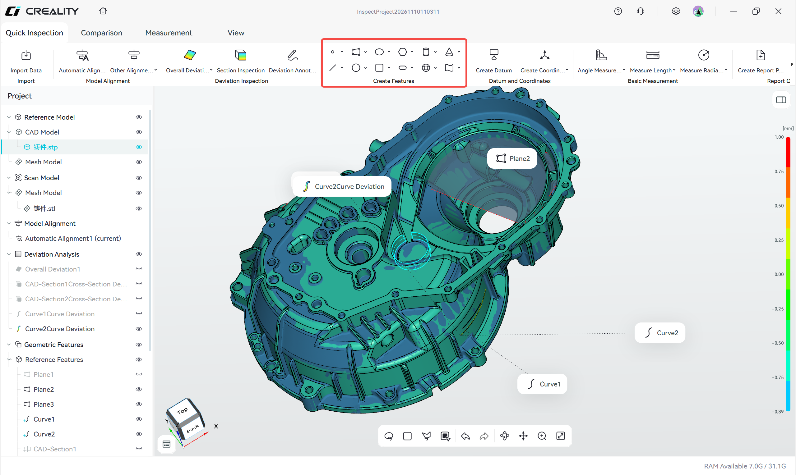
Caption: Figure 5-2-8 Method 1: create a line feature on the CAD model
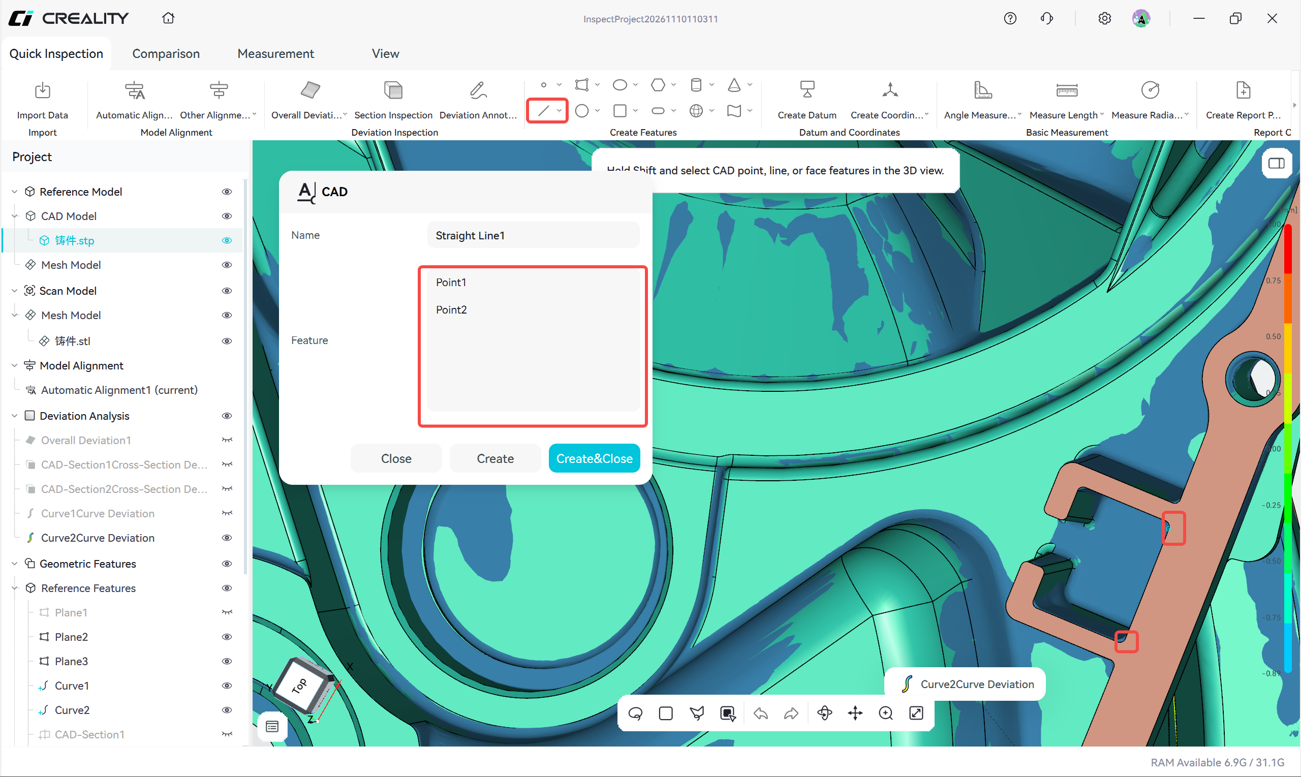
Caption: Figure 5-2-9 The created line feature
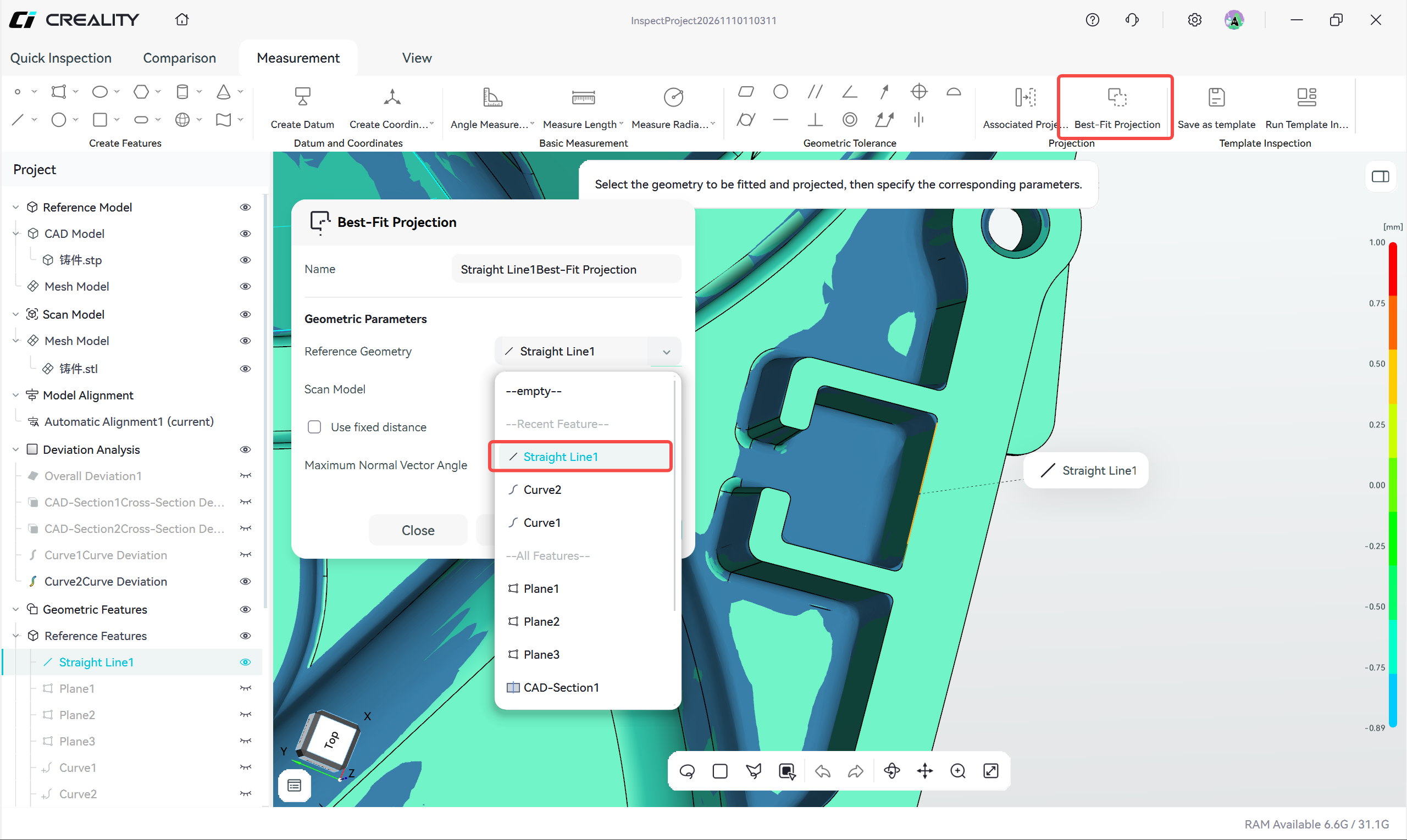
Caption: Figure 5-2-10 Apply Best-Fit Projection to the line feature
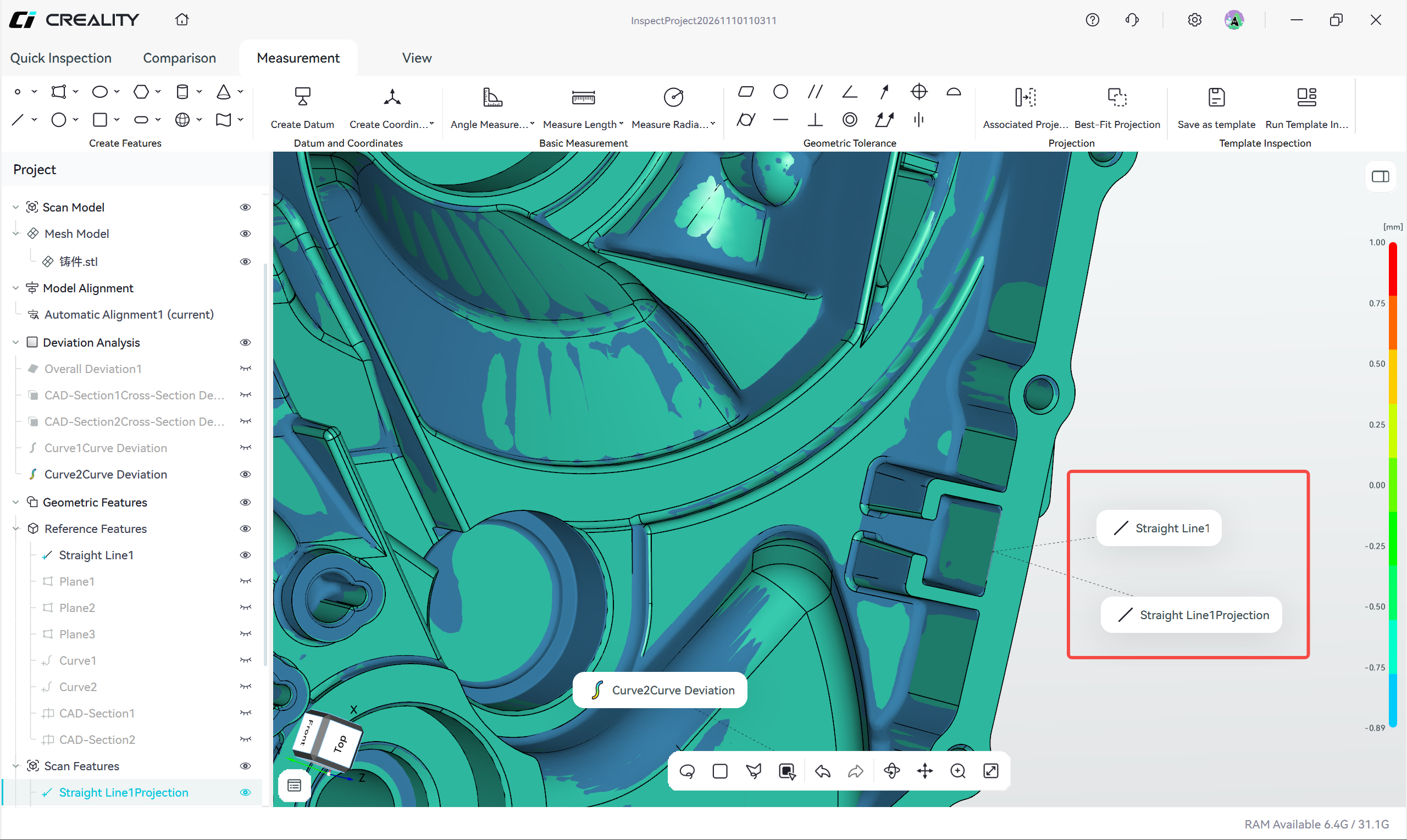
Caption: Figure 5-2-11 The line after Best-Fit Projection
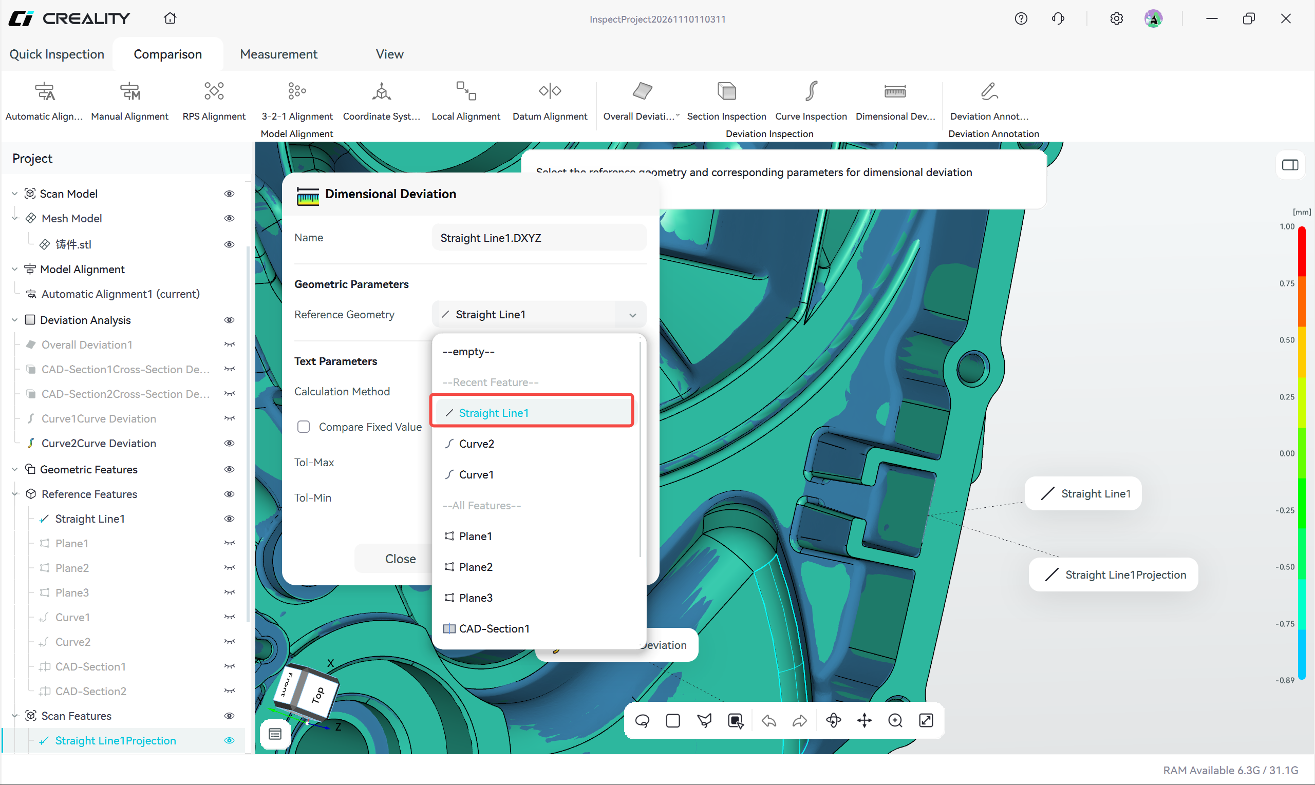
Caption: Figure 5-2-12 Run Dimensional Deviation
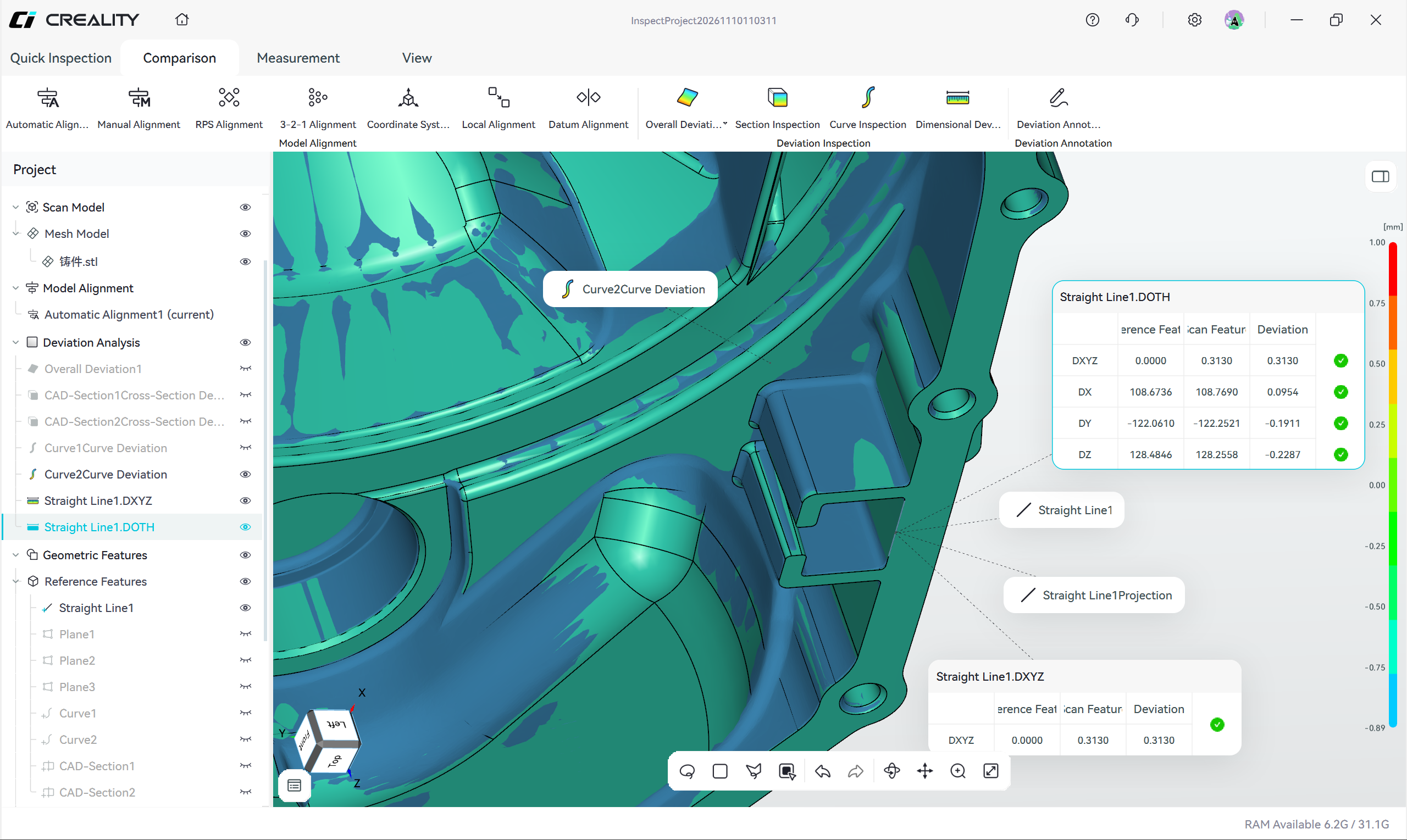
Caption: Figure 5-2-13 Dimensional deviation result
Method 2: Associated Projection (features created on both sides, then associated manually)
Create features on the reference model and on the scan model separately, then establish their correspondence manually through Associated Projection.
Typical use: the scan model already has usable fitted features, or the correspondence between the two features must be controlled precisely.
Operation steps:
- Complete model alignment
- Create the reference feature on the reference model in CAD mode
- Create the corresponding scan feature on the scan model in Fit mode
- Click Associated Projection
- Select the reference feature
- Select the scan feature
- Click Create to complete the association
- Click Dimensional Deviation
- Select the associated features to compare
- Set the tolerance
- Run the calculation and view the nominal value, actual value, deviation, and pass/fail status
The reference feature and the scan feature must be located at the same structural position of the part and must be of the same geometric type (line to line, circle to circle, plane to plane). Otherwise the association cannot be established or the result is invalid.
Differences Between the Two Association Methods
| Item | Best-Fit Projection | Associated Projection |
|---|---|---|
| Feature creation | Only on the reference model | On both the reference model and the scan model |
| Source of scan feature | Fitted automatically by the software from the reference feature | Created manually by the user |
| Workload | Low; one projection completes the task | Higher; two features must be created and associated |
| Control precision | Depends on the fitting range and scan data quality | Better controllability; correspondence can be confirmed item by item |
| Typical use | Regular structures, complete scan data, efficiency-oriented | Incomplete scan data, complex structures, precise control required |
After the association is established by either method, the operation steps, result fields, and judgment rules of Dimensional Deviation are identical.
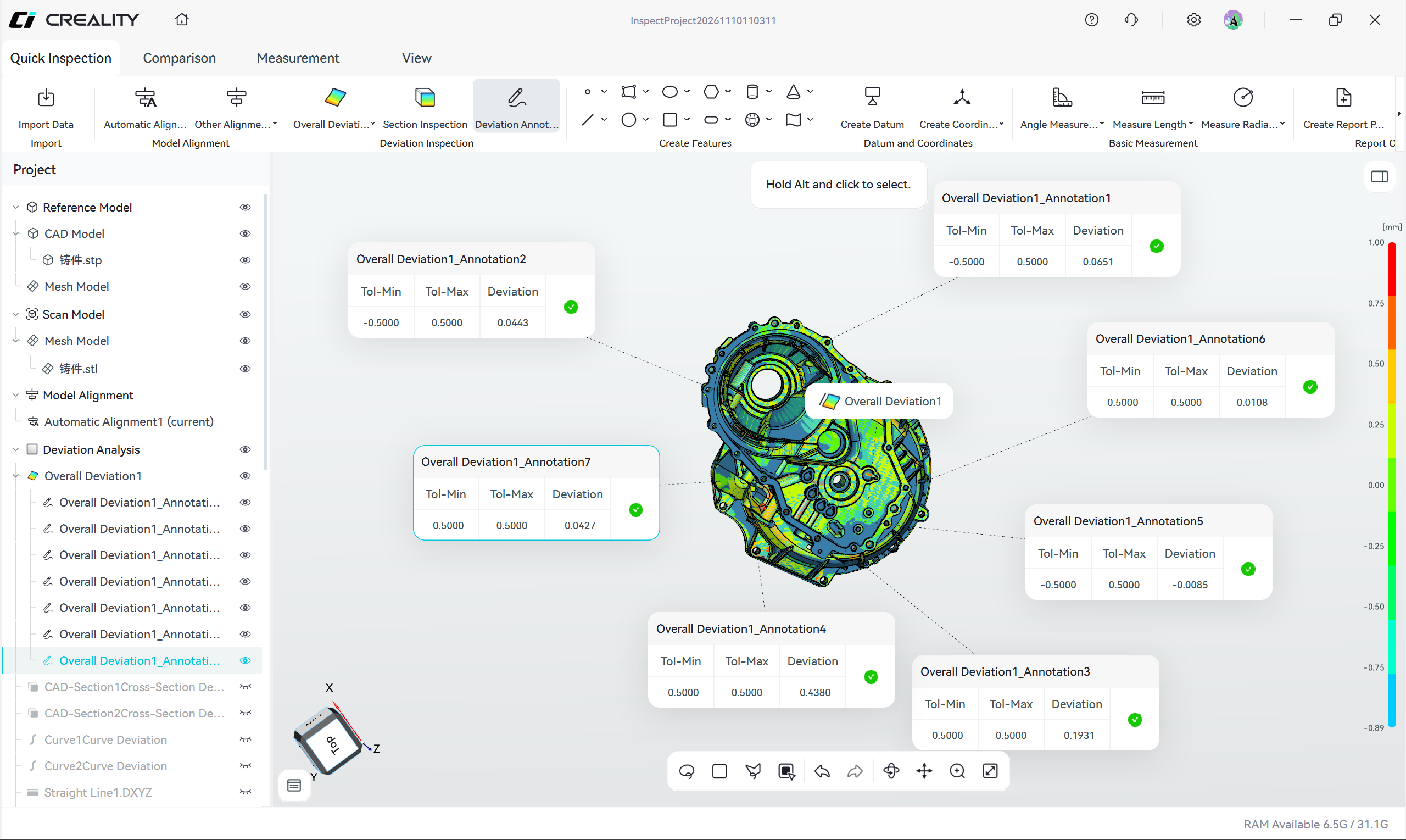
5.2.5 Deviation Annotation
Selects positions on the deviation map and displays the deviation value, tolerance range, and pass/fail status
Before use, complete the calculation of Overall Deviation, Cross-Section Deviation, or Curve Deviation.
Operation steps:
- Click Deviation Annotation
- Select the deviation result to be annotated
- Select the annotation position on the deviation map
- Set the content to be displayed
- Complete the annotation
- View the deviation value and pass/fail status
Deviation annotations can display:
- Deviation value
- Tolerance lower limit
- Tolerance upper limit
- Pass/fail status
Tip: annotations can be dragged by holding Shift. After the deviation result is deleted or recalculated, the corresponding annotations may need to be regenerated.
Caption: Figure 5-2-14 Deviation annotation result
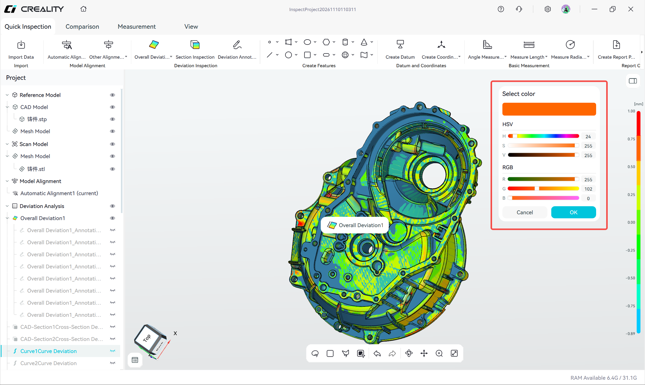
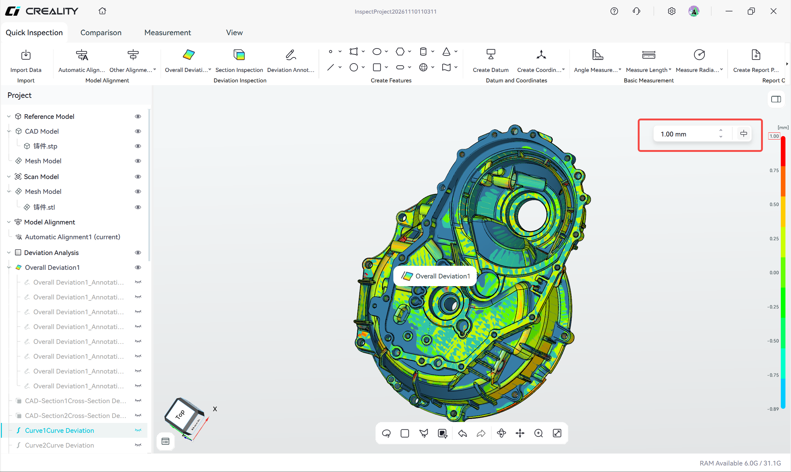
5.2.6 Customizing the Color Scale
Adjusts the deviation range, tolerance range, and color display according to inspection requirements
Operation steps:
- Open the color scale settings
- Set the maximum and minimum deviation values
- Set the tolerance upper limit and tolerance lower limit
- Modify the colors of different ranges as needed
- Apply the settings
- View the updated deviation map
The color scale configuration is saved with the current project and applied to the inspection report.
Caption: Figure 5-2-15 Modify color scale colors
Caption: Figure 5-2-16 Modify color scale values
¶ 6 Measurement Module
¶ 6.1 Selecting Measurement Targets
Measurement targets can be selected in three ways:
- Drop-down selection: select an existing feature from the drop-down list in the measurement dialog
- Shift selection: hold Shift and click an existing feature directly in the 3D view
- Shift quick point creation: hold Shift and click a position on the model where no feature exists yet; the software automatically creates a point feature and uses it for the current measurement — an extracted point on the CAD model or a fitted point on the scan model
Point features created quickly with Shift are also listed under Geometric Features in the project tree and can be reused in later inspections.
This section applies to Angle Measurement, Measure Length, and Measure Radial Distance in Basic Measurement.
¶ 6.2 Create Features
Create geometric features for alignment, measurement, and inspection from the CAD model, the scan model, or existing features.
6.2.1 Supported Feature Types
| Category | Features |
|---|---|
| Basic features | Point, line, plane |
| Profile features | Circle, ellipse, rectangle, polygon, slot, surface |
| Revolved features | Cylinder, sphere, cone |
A feature belongs to the model on which it is created. Subsequent alignment, measurement, geometric tolerance, and dimensional deviation can only reference features on the corresponding model, so confirm the target model before creating features.
6.2.2 Creation Modes and Applicable Models
| Creation Mode | Applicable Model | Description |
|---|---|---|
| CAD | CAD model | Extracts the corresponding geometric element from the CAD model |
| Fit | Scan model | Fits a geometric feature from a scan mesh region |
| Other creation modes | CAD model, scan model | Constructs a new feature from existing features or geometric relations |
When selecting a creation mode, note the following:
- With CAD, elements can only be selected on the CAD model
- With Fit, mesh regions can only be selected on the scan model
- With other creation modes, features already created on the CAD model or the scan model can be used
- If the creation mode depends on other features, create the dependent features first
- CAD mode is mainly used to extract points, lines, planes, and other geometric elements; revolved features such as circles, cylinders, and spheres are generally obtained from scan data in Fit mode
The overall workflow is the same for all three modes: select the feature type → select the creation mode → select the object → set the parameters → create. The operation details of each mode are described below.
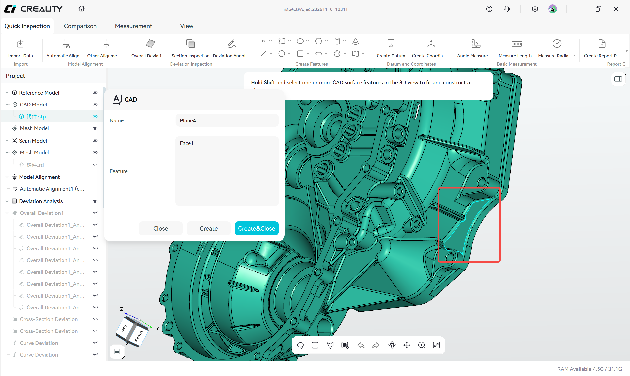
6.2.3 CAD Mode
Extracts geometric elements such as points, lines, or planes from the CAD model
Operation steps:
- Select Point, Line, or Plane
- Set the creation mode to CAD
- Select the CAD model
- In the 3D view, hover the mouse over the target face; the software automatically recognizes and highlights the face — click to select it
- Check the selected elements in the dialog and rename the feature if necessary
- Click Create to complete the current creation and continue creating, or click Create&Close to create and close the dialog
Tip: hold Shift to select multiple CAD faces consecutively in the 3D view and create multiple features at once. CAD mode cannot be used on the scan model.
Caption: Figure 6-2-1 Creating a plane feature in CAD mode: hovering automatically recognizes and highlights the target face
6.2.4 Fit Mode
Selects a target region on the scan mesh and fits the corresponding geometric feature
Fit mode is commonly used to create fitted points, lines, planes, circles, cylinders, cones, and spheres.
Before use, import the scan model and confirm that the scan mesh contains a target region that can be fitted.
Operation steps:
- Select the feature type to create
- Set the creation mode to Fit
- Select the scan model
- Select the target position or region on the scan mesh
- Adjust the mesh selection as needed
- Check the position, orientation, and size of the fitted feature
- Click Create to complete the current creation and continue creating, or click Create&Close to create and close the dialog
Notes on fitting:
- When fitting a point, select the target position on the scan mesh
- When fitting a line, plane, circle, cylinder, cone, or sphere, select a mesh region that represents the target shape
- The selection should cover the complete target region as far as possible
- Avoid including adjacent surfaces, noise points, or unrelated mesh
- If the fitting result is affected by noise, adjust the fitting parameters (such as the rejection threshold) and fit again
Fitted features can be used for Manual Alignment, 3-2-1 Alignment, datum and coordinate system creation, basic measurement, geometric tolerance evaluation, dimensional deviation, and feature projection.
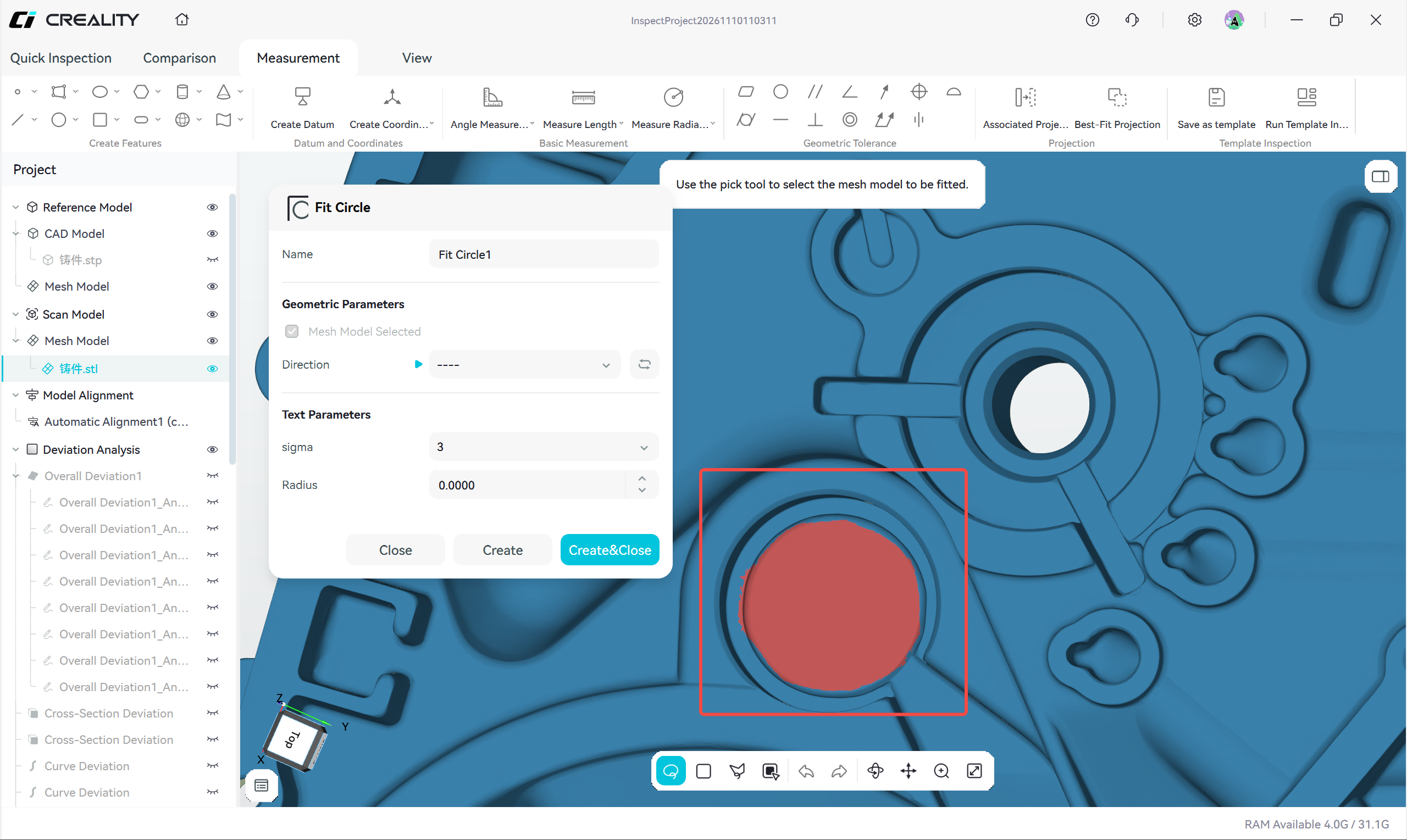
Caption: Figure 6-2-2 Select the fitting region on the scan mesh
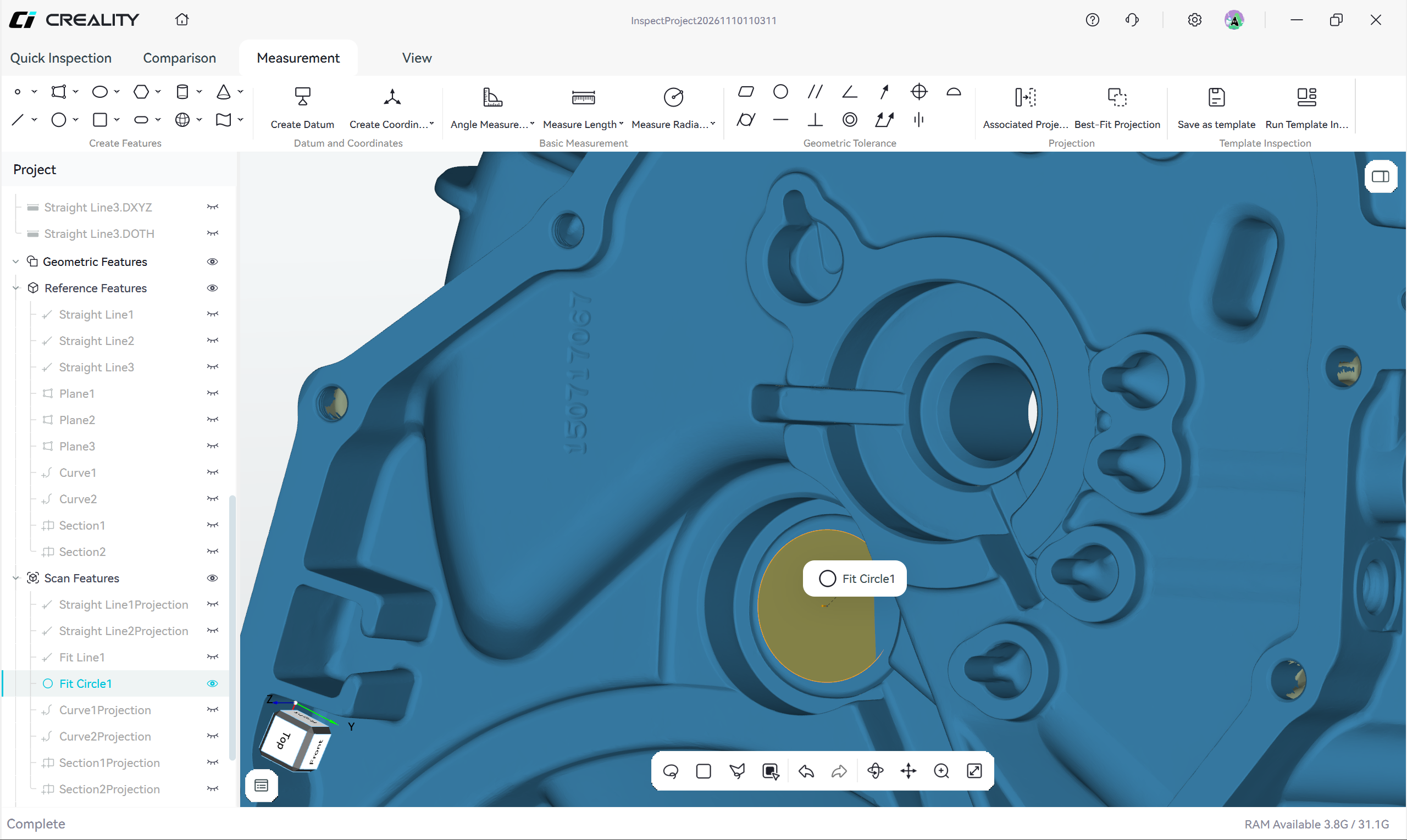
Caption: Figure 6-2-3 The fitted feature
6.2.5 Other Creation Modes
Constructs new features on the CAD model or the scan model from existing features or geometric relations
This mode can use features on the CAD model or features on the scan model, but the dependent features must be created in advance.
Common construction methods:
| Construction Method | Description | Typical Use |
|---|---|---|
| Intersection of two features | Constructs an intersection line or point from two planes or lines | Extracting parting lines and edges |
| Midpoint / endpoint | Derives a feature point from an existing line or circle | Establishing alignment locating points |
| Offset | Generates an offset feature at a specified distance from a plane or line | Building inspection datum planes |
Operation steps:
- Select the feature type to create
- Select the corresponding construction mode
- Select the dependent features in order
- Set parameters such as direction, position, or offset
- Check the feature preview
- Click Create to complete the current creation and continue creating, or click Create&Close to create and close the dialog
If an object cannot be selected, check whether the dependent features have been created and whether the feature type and selection order meet the requirements of the current construction mode.
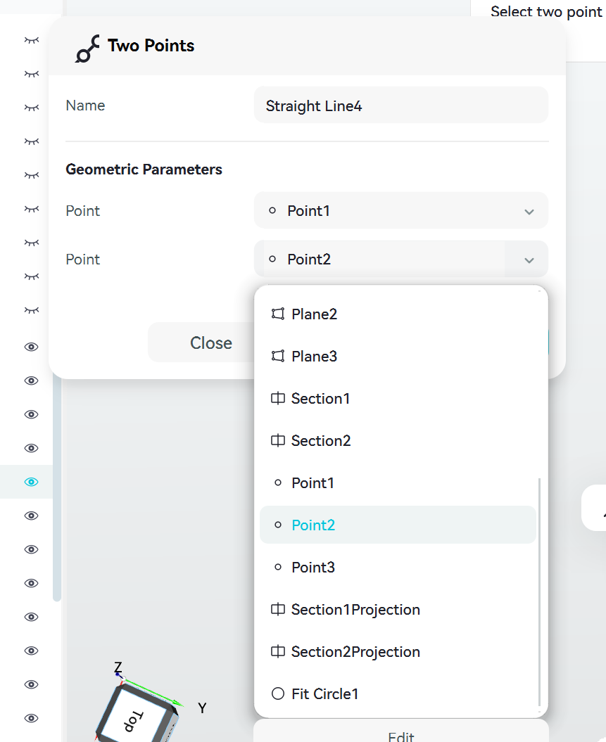
Caption: Figure 6-2-4 Create a line from two points
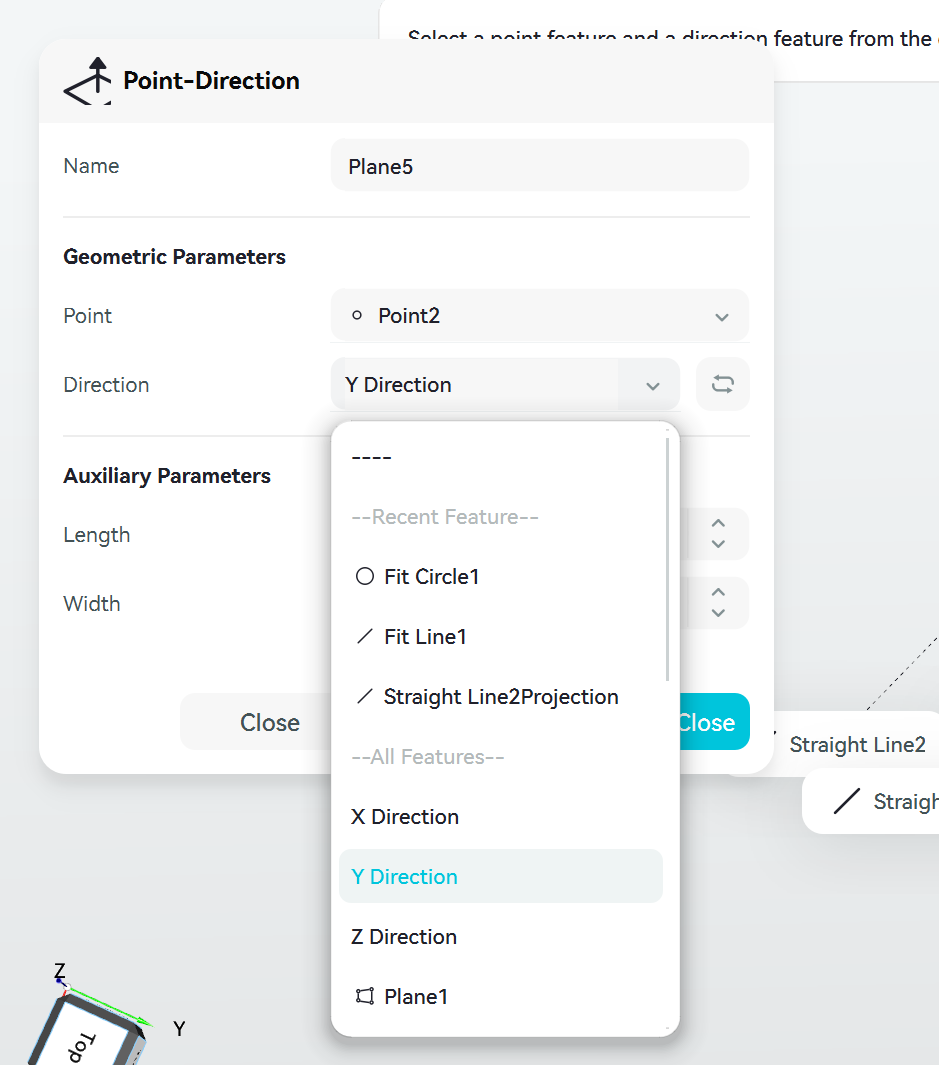
Caption: Figure 6-2-5 Create a plane from a point and a direction
6.2.6 Feature Management
Created features are listed under Geometric Features in the project tree and can be renamed, centered, hidden, or deleted. After selecting multiple features at the same level, right-click and select Group to build a group.
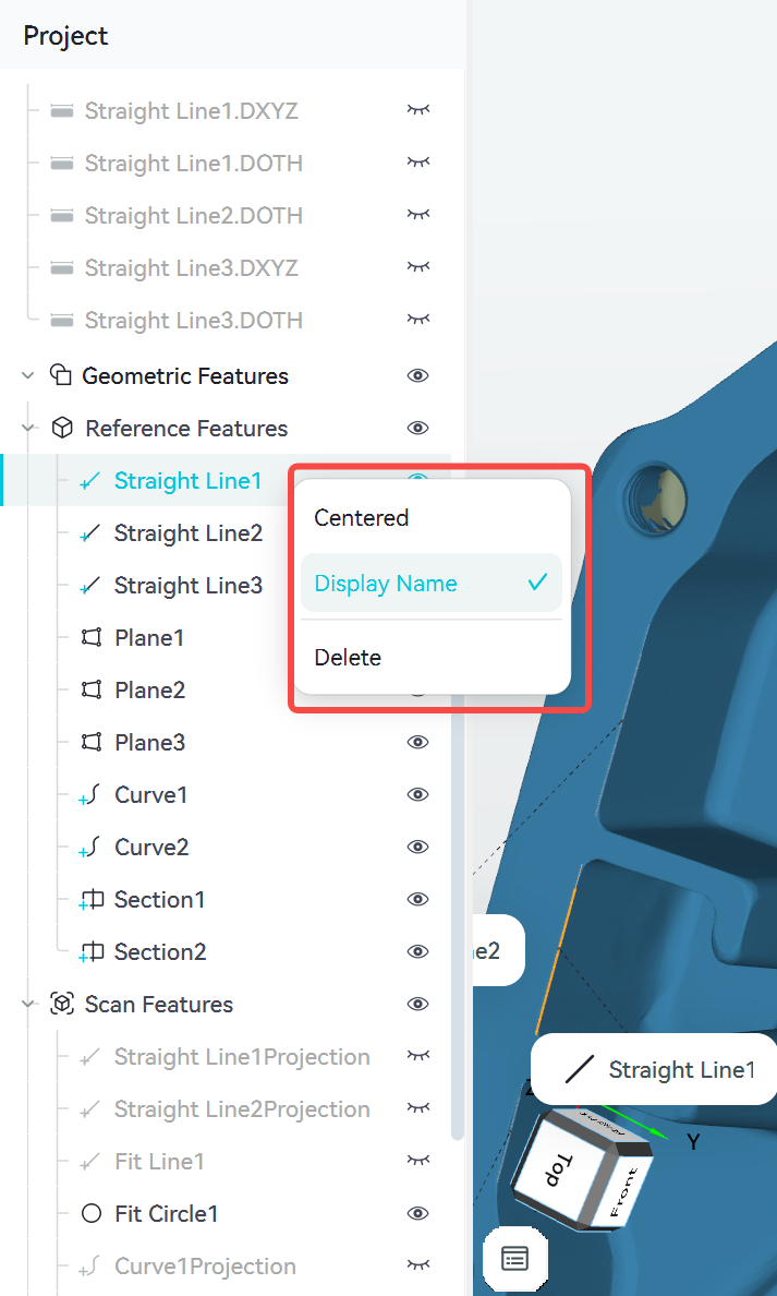
Caption: Figure 6-2-6 Project tree context menu: centered, hidden, and deleted
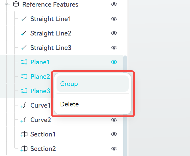
Caption: Figure 6-2-7 Build a group after selecting multiple items
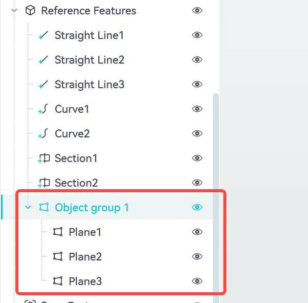
Caption: Figure 6-2-8 Grouping result
¶ 6.3 Datum and Coordinates
6.3.1 Datum
A datum is the reference used in geometric tolerances to determine the orientation and position of a geometric feature. The selection and order of datums directly determine the evaluation result.
6.3.1.1 Datum Composition
A datum is composed of features such as points, lines, and planes. The features used to construct a datum must first be generated through Create Features. The composition and applicability of datums are listed below.
Type Composition Applicability
Single datum One feature, such as a plane, a line, a point, or a circle When the drawing specifies only one datum
Multiple datums 2–3 features, such as line-plane, plane-plane, or a combination of three planes When the drawing specifies multiple datums with a defined order
Compound datum Multiple features of the same type or related features selected in the same input box When the same datum is composed of multiple features on the drawing
6.3.1.2 Rules
- Feature selection: a datum constructed from non-fitted features (for example, mesh data taken directly) can participate in geometric tolerance calculations, but the evaluation result does not conform to geometric tolerance specifications and is for self-check reference only.
- Feature dependency: if an upstream feature is modified, the datum must be rebuilt, and the geometric tolerance results that reference the datum must be recalculated.
- Priority order: among multiple datums, the first datum is the primary datum; the parallelism or perpendicularity of the second and third datums is subordinate to the primary datum. The datum order must match the drawing; a different order gives a different evaluation result for the same workpiece.
- Constraint method: the first datum is created independently; the second datum is created under the constraint of the first datum; the third datum is created within the system formed by the first and second datums.
- Degrees of freedom: a datum point or datum circle constrains 3 translational degrees of freedom; a datum line or axis constrains 4 degrees of freedom (2 translational and 2 rotational); a datum plane constrains 3 degrees of freedom (1 translational and 2 rotational).
- Redundant constraints are ineffective: adding more datums after the degrees of freedom are fully constrained is a redundant constraint and does not improve evaluation reliability.
6.3.1.3 Creating a Datum
- Typical use: geometric tolerances that require judging the orientation and position of geometric features, or building a datum system according to a CAD drawing.
- Constraint basis: point, line, and plane features, input in the datum order specified on the drawing.
- Prerequisites: the required point, line, plane, or cylinder features have been constructed on the model; fitted features should be used to construct the datum.
Steps:
- Click Datum;
- Select features into Datum 1, Datum 2, and Datum 3. You can click a feature in the view to fill it in automatically, or select an existing feature from the drop-down list;
- Click Create to generate the datum.
Note: the software filters the input features according to the datum creation rules above and adopts only the features that meet the rules; other features do not participate in the creation.
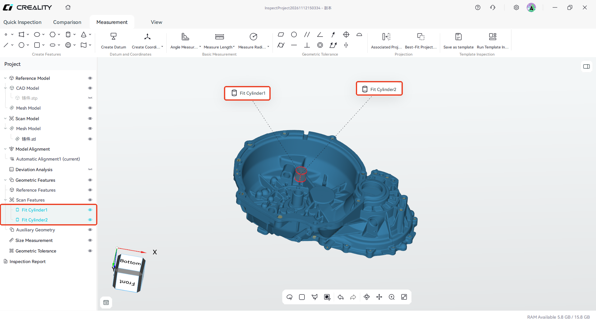
Caption: Figure 6-3-1 Create a fitted cylinder on the scan model
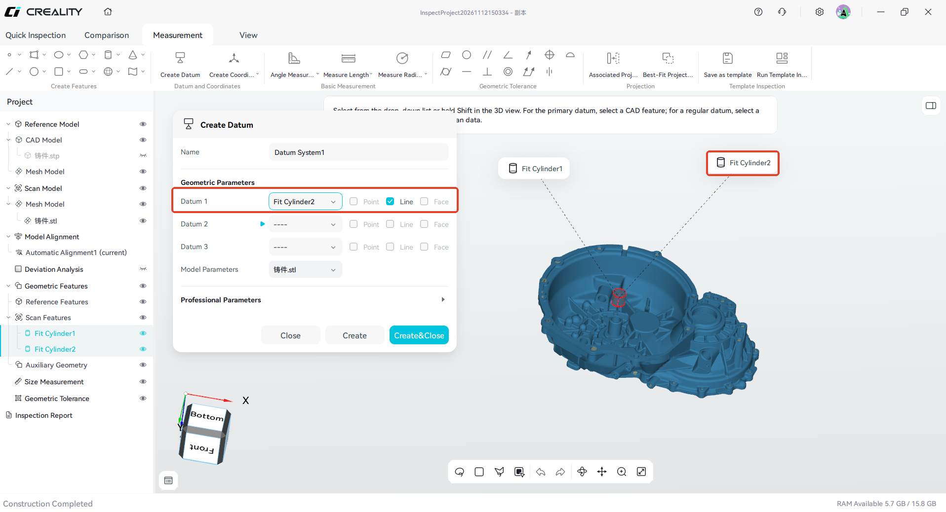
Caption: Figure 6-3-2 Select a fitted cylinder that meets the datum rules as an axis datum
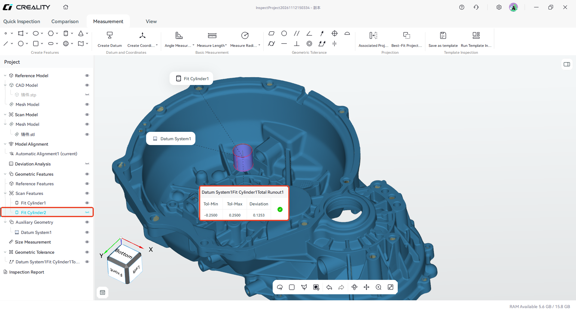
Caption: Figure 6-3-3 Use the axis datum to measure the geometric tolerance (total runout) of the fitted cylinder
6.3.2 Coordinate System
A coordinate system is a reference coordinate system with a specified axis orientation and origin. It supports the coordinate transformation and evaluation of geometric features, as well as coordinate system alignment of models.
6.3.2.1 Coordinate System Composition
A coordinate system is constructed from point, line, and plane features according to rules. Two construction methods are available: plane-line-point and line-line-point. The input features must be constructed in advance.
| Construction Method | Input Features | Axis Rule | Applicability |
|---|---|---|---|
| Plane-line-point | 1 plane, 1 line, 1 point | Taking Z-Y-X as an example: the plane defines the Z direction, the cross product of the plane and the line defines the Y direction, and the X axis passes through the point | Preferred when a reliable plane exists |
| Line-line-point | 2 lines, 1 point | Taking Z-Y as an example: the first line defines the Z direction, the cross product of the first and second lines defines the Y direction, and the origin is located at the point | Used when no reliable plane exists |
6.3.2.2 Rules
- Feature selection: construct the features first, then the coordinate system. The two lines must not be parallel or coincident; otherwise the cross product direction cannot be determined.
- Axis constraint: if the axis orientation is opposite to the CAD drawing or the fixture clamping direction, adjust the construction rule instead of rotating the model.
- Feature dependency: if an upstream feature is modified, the coordinate system must be rebuilt, and the registration and measurement that reference it must be recalculated.
6.3.2.3 Creating a Coordinate System
Plane-Line-Point
- Typical use: the workpiece has clear plane, line, and point features from which the coordinate system can be determined.
- Constraint basis: 1 plane, 1 line, 1 point.
- Prerequisites: the three features above have been constructed; the point can also be constructed as a temporary point by point picking.
Steps:
- Click Create Coordinate System in the construction bar and select From Plane-Line-Point;
- In the 3D view, select the existing point, line, and plane geometric features, or select them from the drop-down list in the dialog;
- Set the rule in the auxiliary parameters to define the arrangement of the X, Y, and Z axes;
- Click Create to generate the coordinate system.
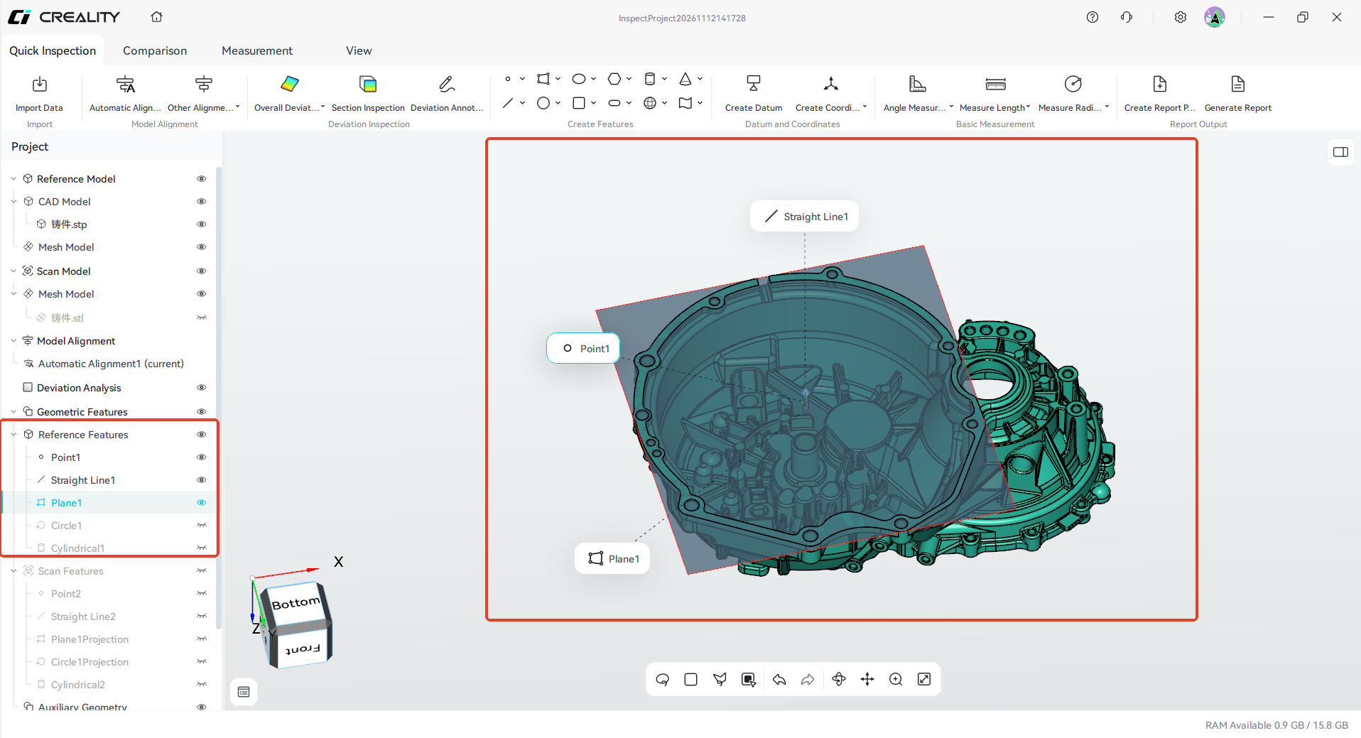
Caption: Figure 6-3-4 Construct the point, line, and plane features required for the coordinate system
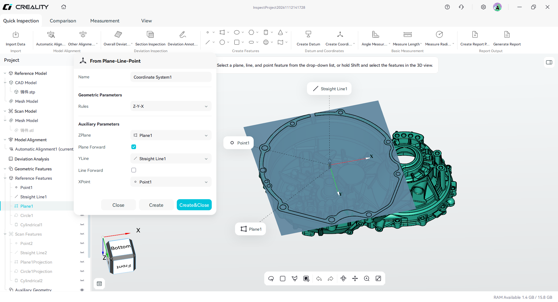
Caption: Figure 6-3-5 Select the constructed point, line, and plane features
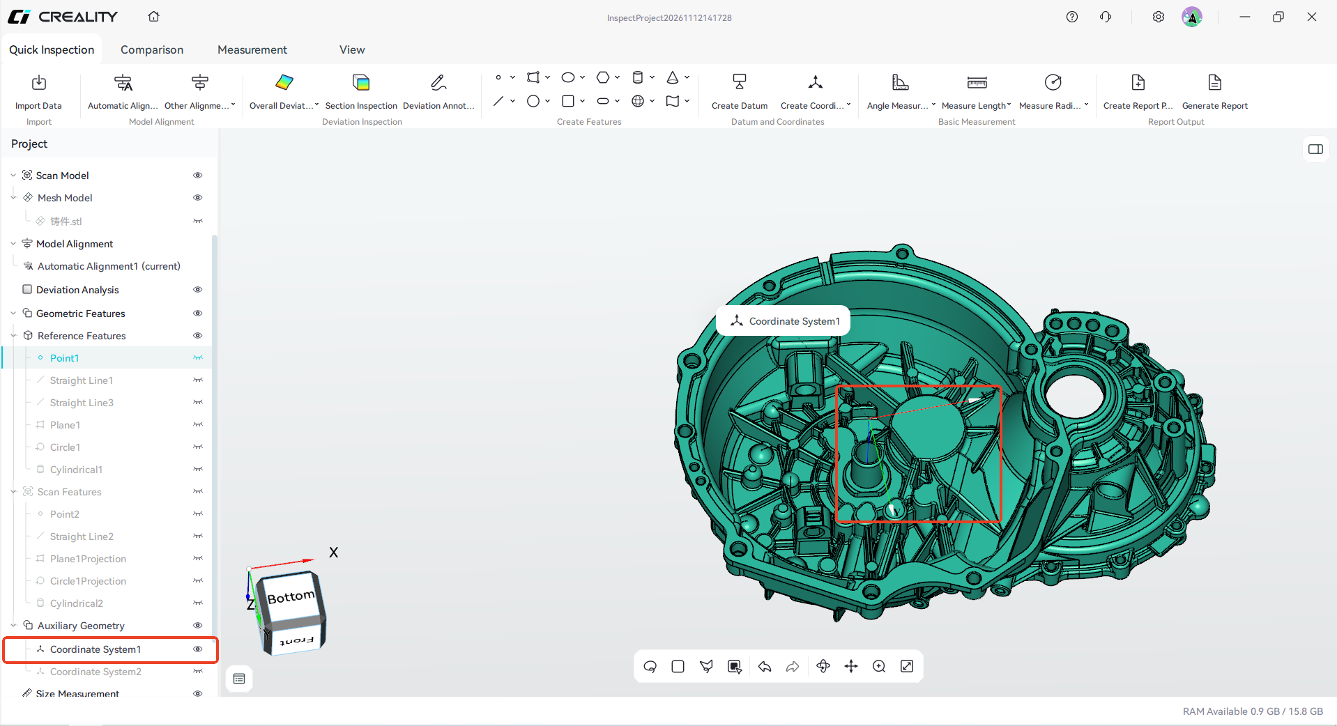
Caption: Figure 6-3-6 Plane-line-point coordinate system created
Line-Line-Point
- Typical use: the workpiece has no reliable plane, or two axes are needed to determine the orientation.
- Constraint basis: 2 lines and 1 point; the two lines must not be parallel or coincident.
- Prerequisites: two lines and one point have been constructed; the point can be constructed by point picking.
Steps:
- Click Create Coordinate System and select From Line-Line-Point;
- In the 3D view, select the existing point and two lines, or select them from the drop-down list in the dialog;
- Set the rule in the auxiliary parameters to define the arrangement of the X, Y, and Z axes;
- Click Create to generate the coordinate system.
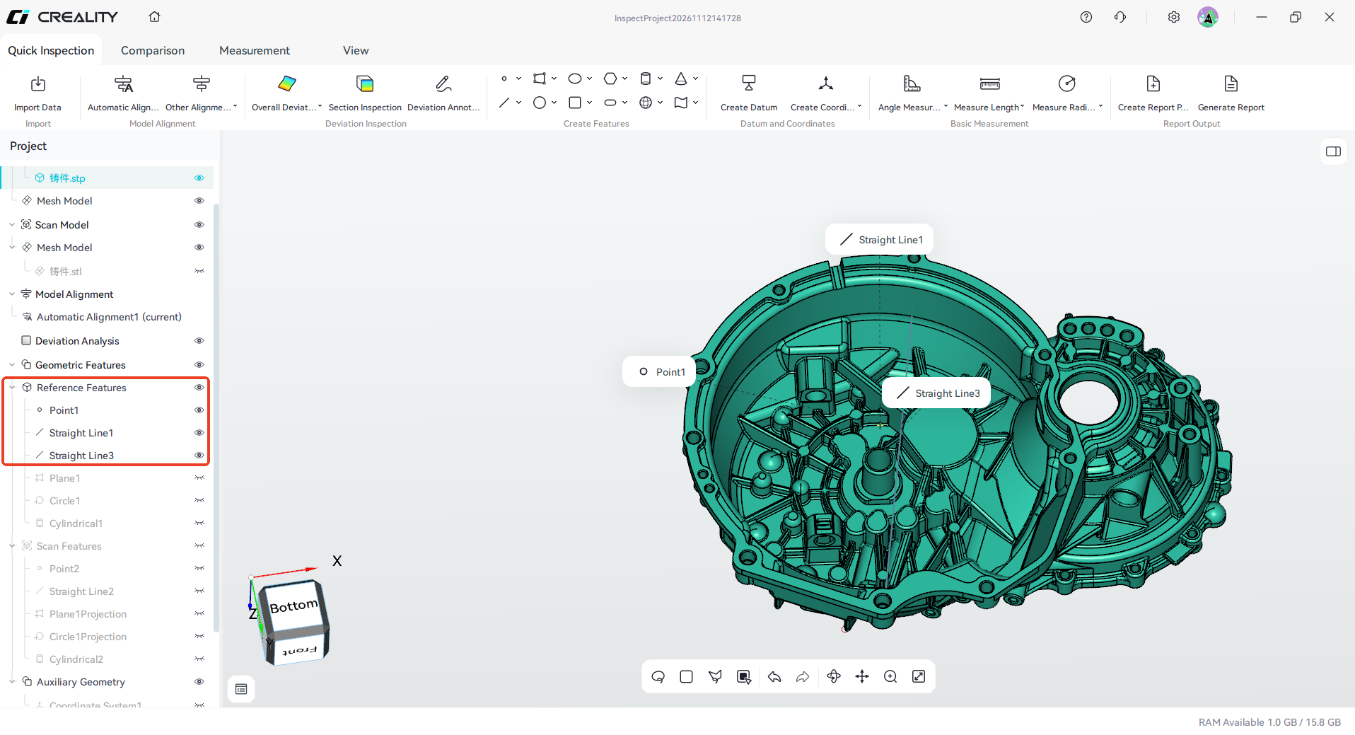
Caption: Figure 6-3-7 Construct the two lines and one point required for the coordinate system
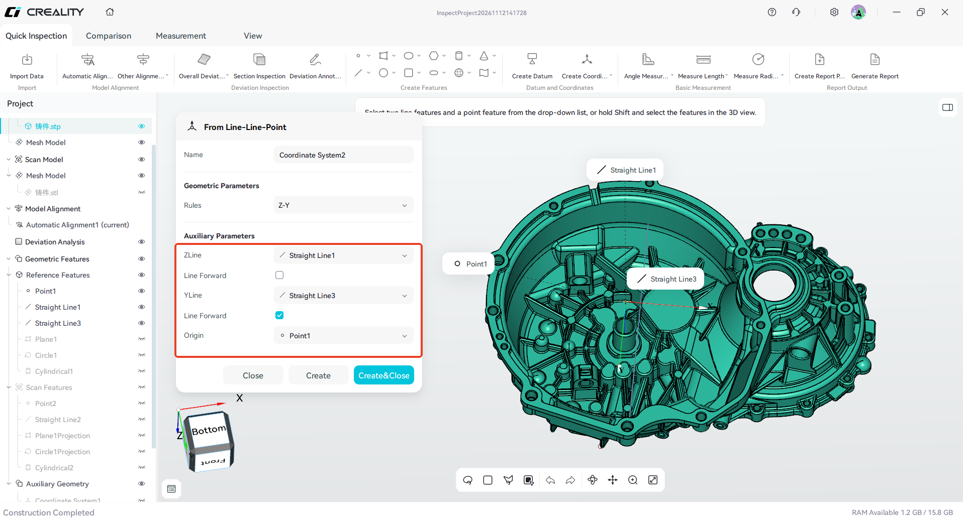
Caption: Figure 6-3-8 Select the constructed two lines and one point
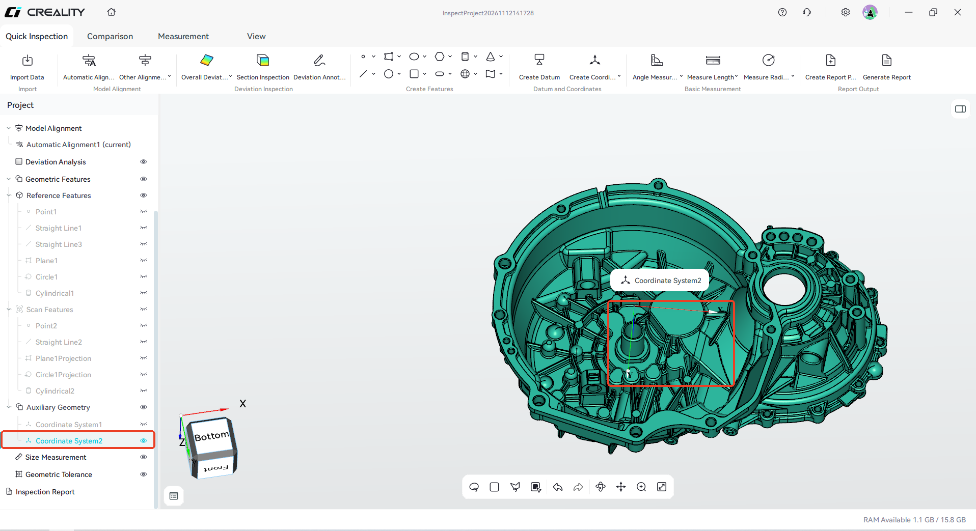
Caption: Figure 6-3-9 Line-line-point coordinate system created
¶ 6.4 Basic Measurement
Basic Measurement includes Angle Measurement, Measure Length, and Measure Radial Distance. For information on selecting measurement targets, see 6.1 "Selecting Measurement Targets".
6.4.1 Angle Measurement
Measures the angle formed by point, line, and plane features
Click the Angle Measurement drop-down and select one of the following methods according to the measurement object:
| Measurement Method | Measurement Object | Required Features |
|---|---|---|
| Three-Point Angle | The angle formed by a vertex and two end points | 3 points |
| Angle Between Two Lines | The angle between two lines or axes | 2 lines |
| Angle Between Two Planes | The angle between two planes | 2 planes |
| Angle Between a Line and a Plane | The angle between a line and a plane | 1 line + 1 plane |
Operation steps:
- Click the Angle Measurement drop-down and select a measurement method
- Select the corresponding point, line, or plane features as prompted
- View the angle value and direction
Notes for each method:
- Three-Point Angle: select in the order "vertex → end point 1 → end point 2"
- Angle Between Two Lines: the two lines may be non-intersecting; the software calculates the angle from their direction vectors
- Angle Between Two Planes: the measured value is the angle between the two plane normals; note the difference from a dihedral angle
- Angle Between a Line and a Plane: the result is 0° when the line is parallel to the plane
Tip: measurement targets can be existing features, or point features created quickly with Shift during selection; see "Selecting Measurement Targets".
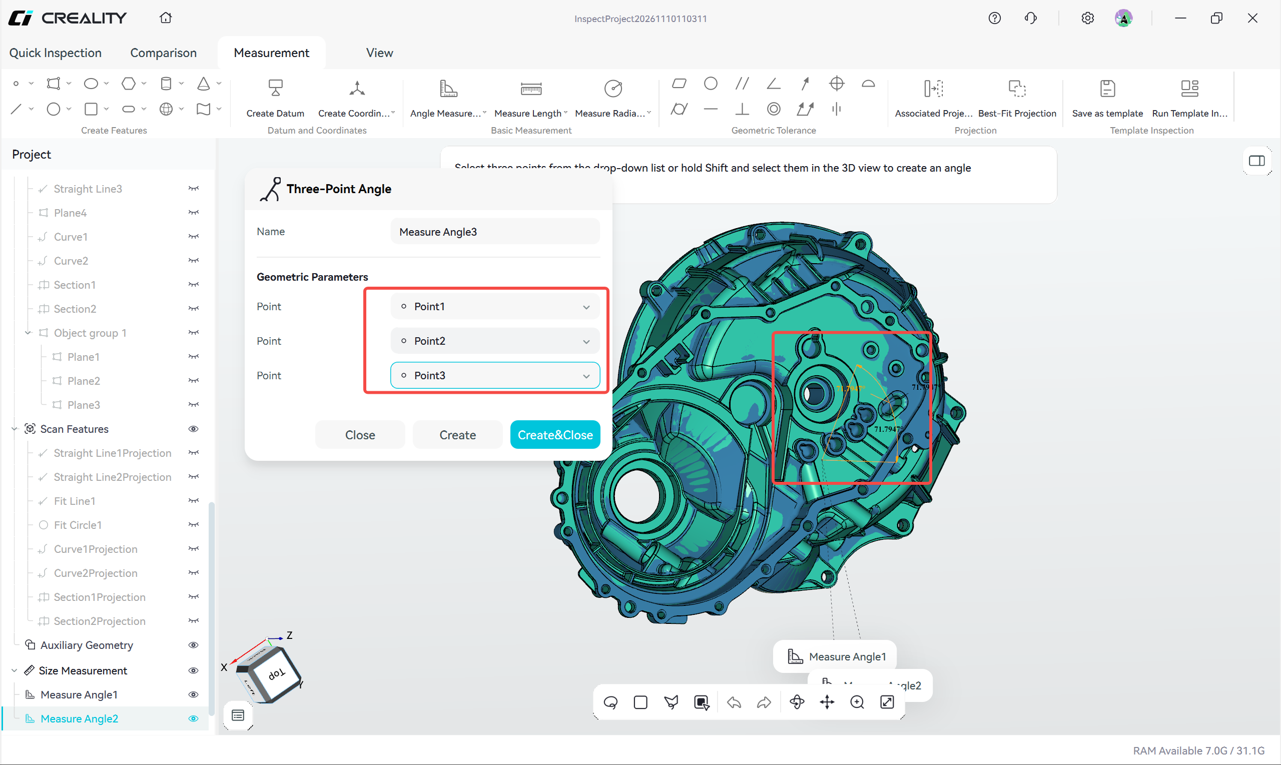
Caption: Figure 6-4-1 Three-Point Angle
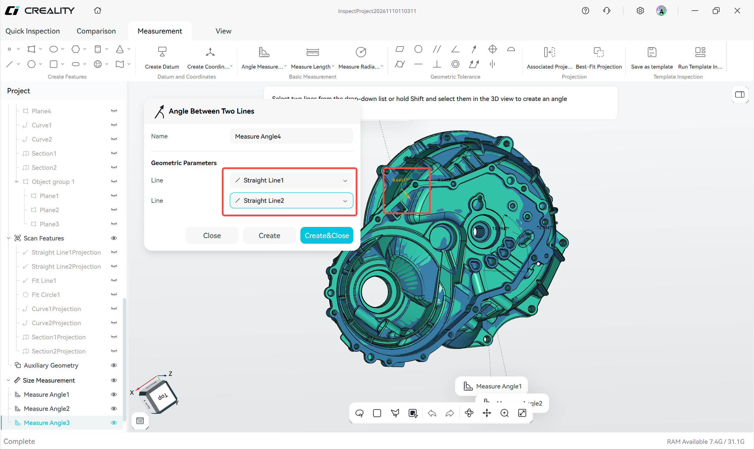
Caption: Figure 6-4-2 Angle Between Two Lines
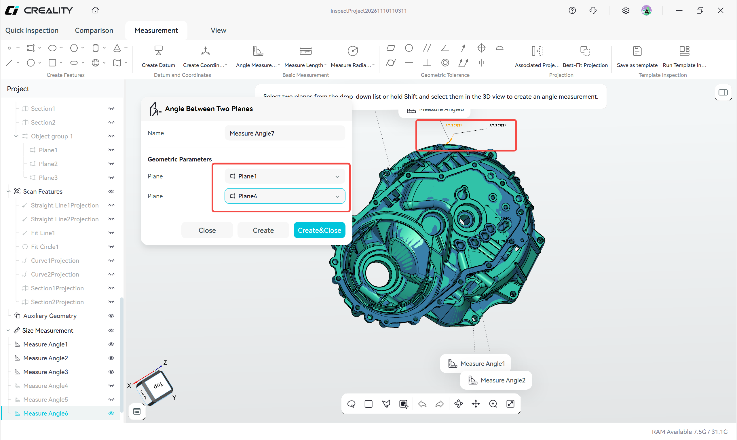
Caption: Figure 6-4-3 Angle Between Two Planes
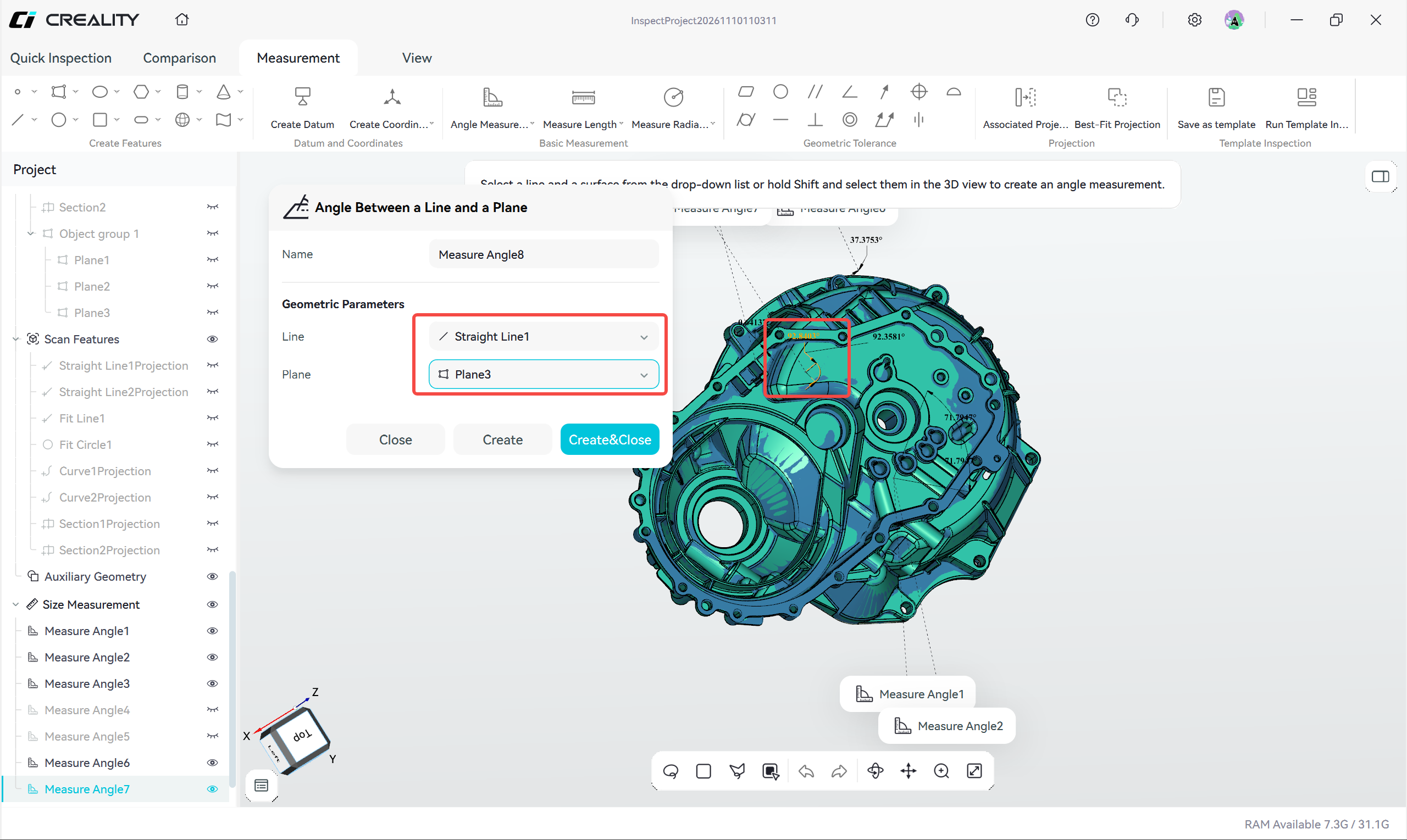
Caption: Figure 6-4-4 Angle Between a Line and a Plane
¶ 6.4.2 Measure Length
Measures the distance between point, line, and plane features
Click the Measure Length drop-down and select one of the following methods according to the measurement object:
Measurement Method Measurement Object Required Features
Distance Between Two Points The distance between two points 2 points
Distance from Point to Straight Line The perpendicular distance from a point to a line 1 point + 1 line
Distance from Point to Plane The distance from a point to a plane 1 point + 1 plane
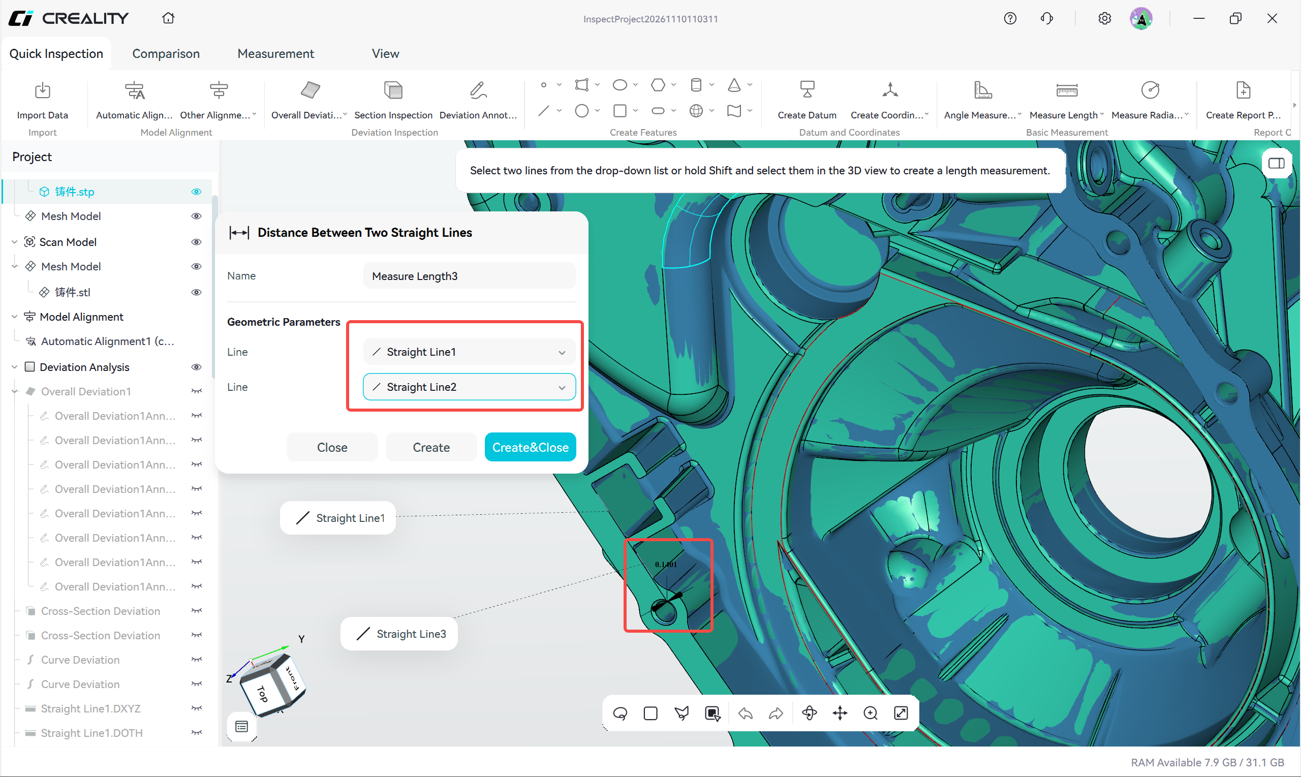
Distance Between Two Straight Lines The distance between two lines 2 lines
Distance from Straight Line to Plane The distance from a line to a plane 1 line + 1 plane
Distance Between Planes The distance between two planes 2 planes
Maximum Distance Between Planes The maximum distance between two planes 2 planes
Operation steps:
- Click the Measure Length drop-down and select a measurement method
- Select the corresponding point, line, or plane features as prompted
- View the measurement value
Notes for each method:
- Distance Between Two Points: directly measures the spatial distance between two point features
- Distance from Point to Straight Line: the result is the length of the perpendicular segment from the point to the line; the point does not need to lie on the line
- Distance from Point to Plane: the result is the distance from the point to the plane along the plane normal
- Distance Between Two Straight Lines: applicable to parallel or skew lines; the distance is 0 for intersecting lines
- Distance from Straight Line to Plane: meaningful only when the line is parallel to the plane; the result is the distance from a point on the line to the plane
- Distance Between Planes: applicable to parallel planes; the result is the normal distance
- Maximum Distance Between Planes: applicable to non-parallel or partially overlapping planes; the result is the maximum distance between the two planes within the selected range
Tip: measurement targets can be existing features, or point features created quickly with Shift during selection; see "Selecting Measurement Targets".
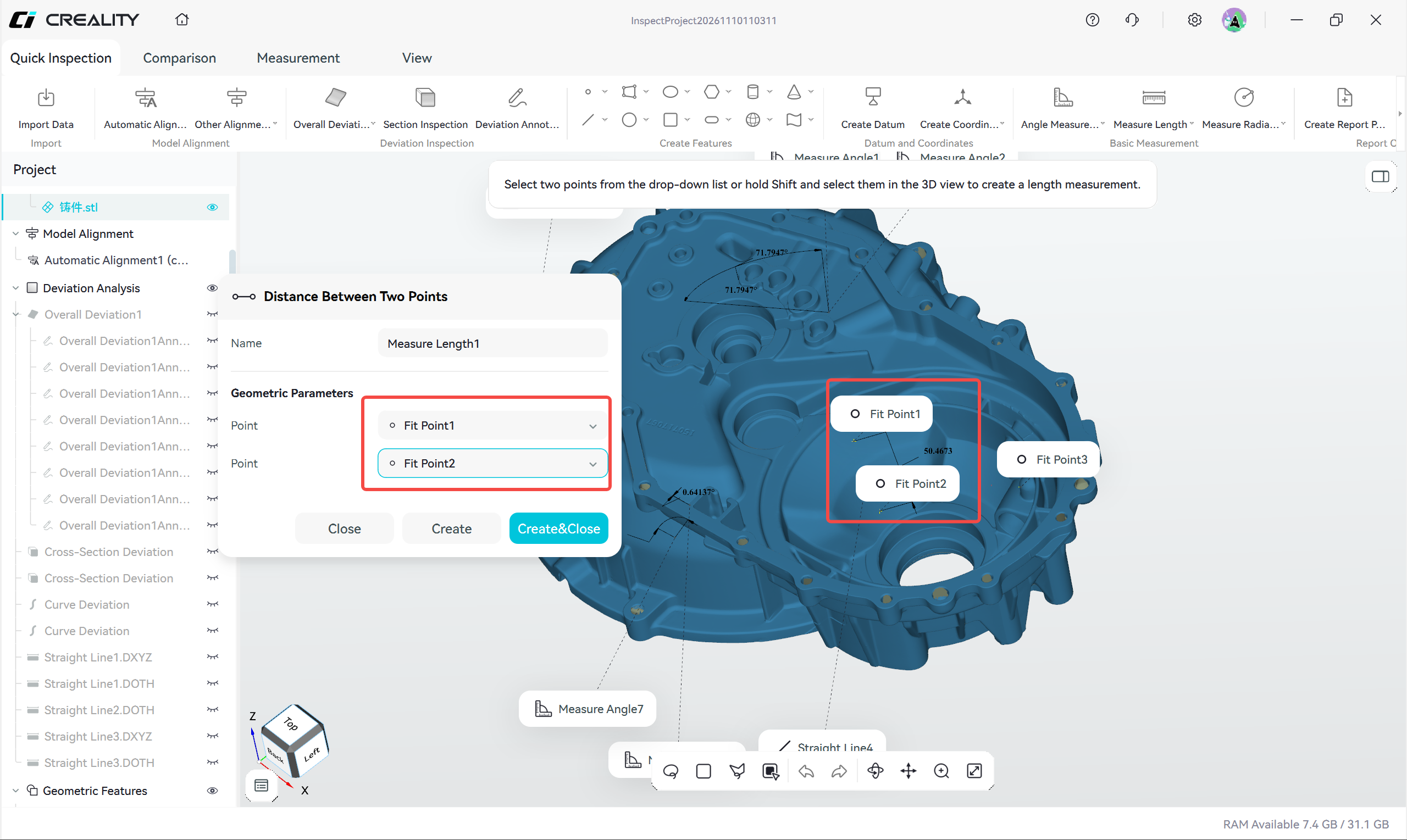
Caption: Figure 6-4-5 Distance Between Two Points
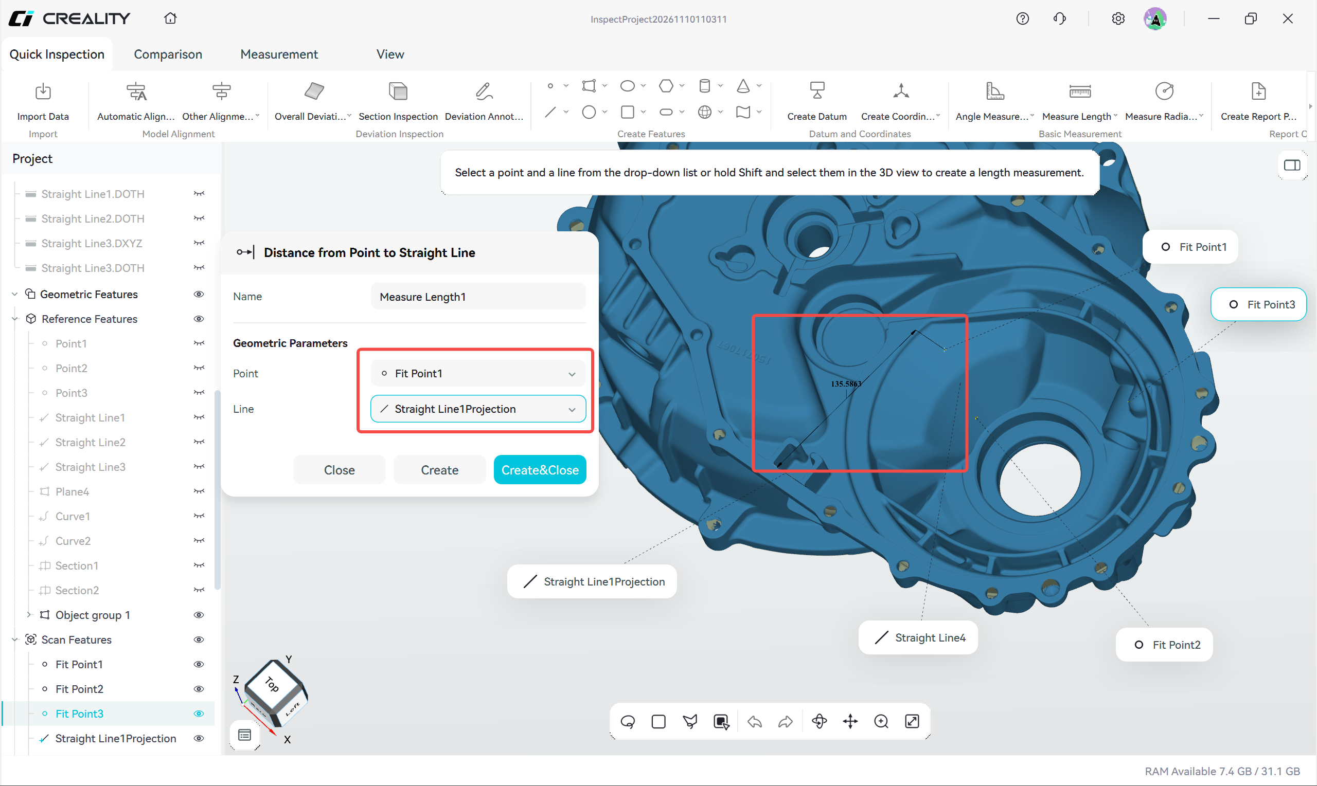
Caption: Figure 6-4-6 Distance from Point to Straight Line
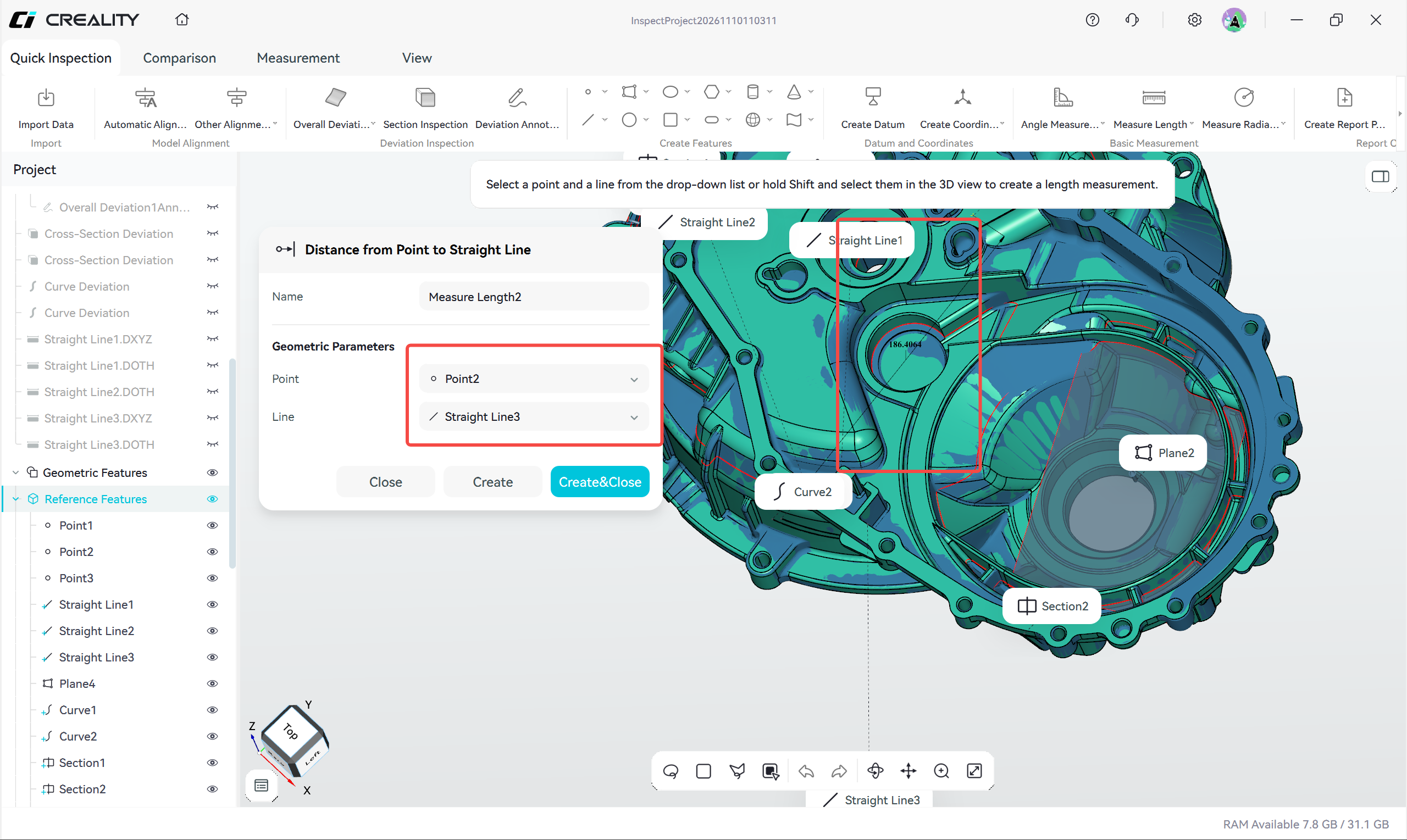
Caption: Figure 6-4-7 Distance from Point to Plane
Caption: Figure 6-4-8 Distance Between Two Straight Lines
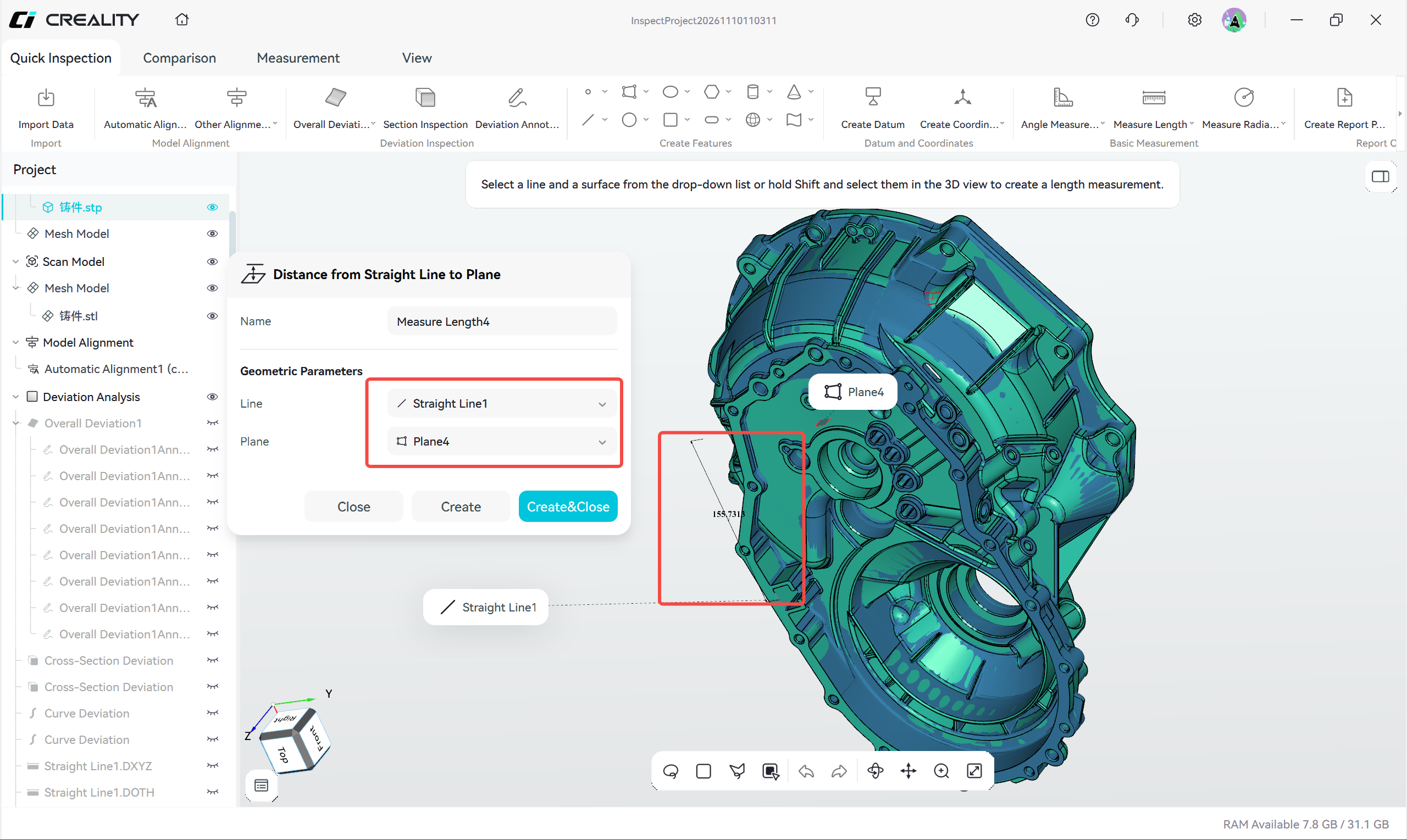
Caption: Figure 6-4-9 Distance from Straight Line to Plane
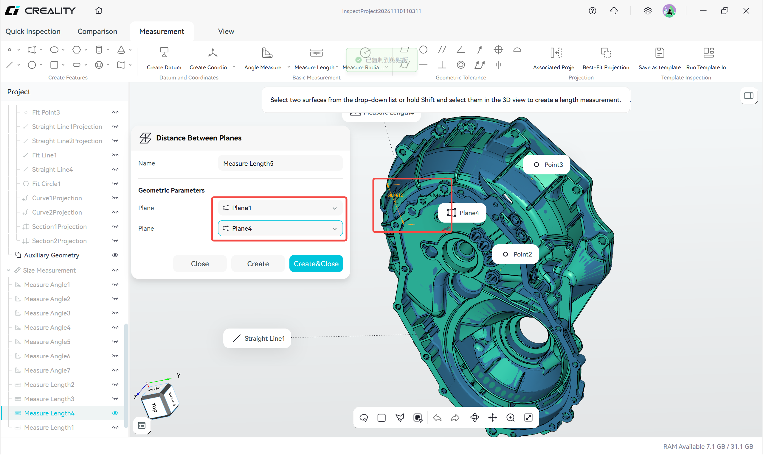
Caption: Figure 6-4-10 Distance Between Planes
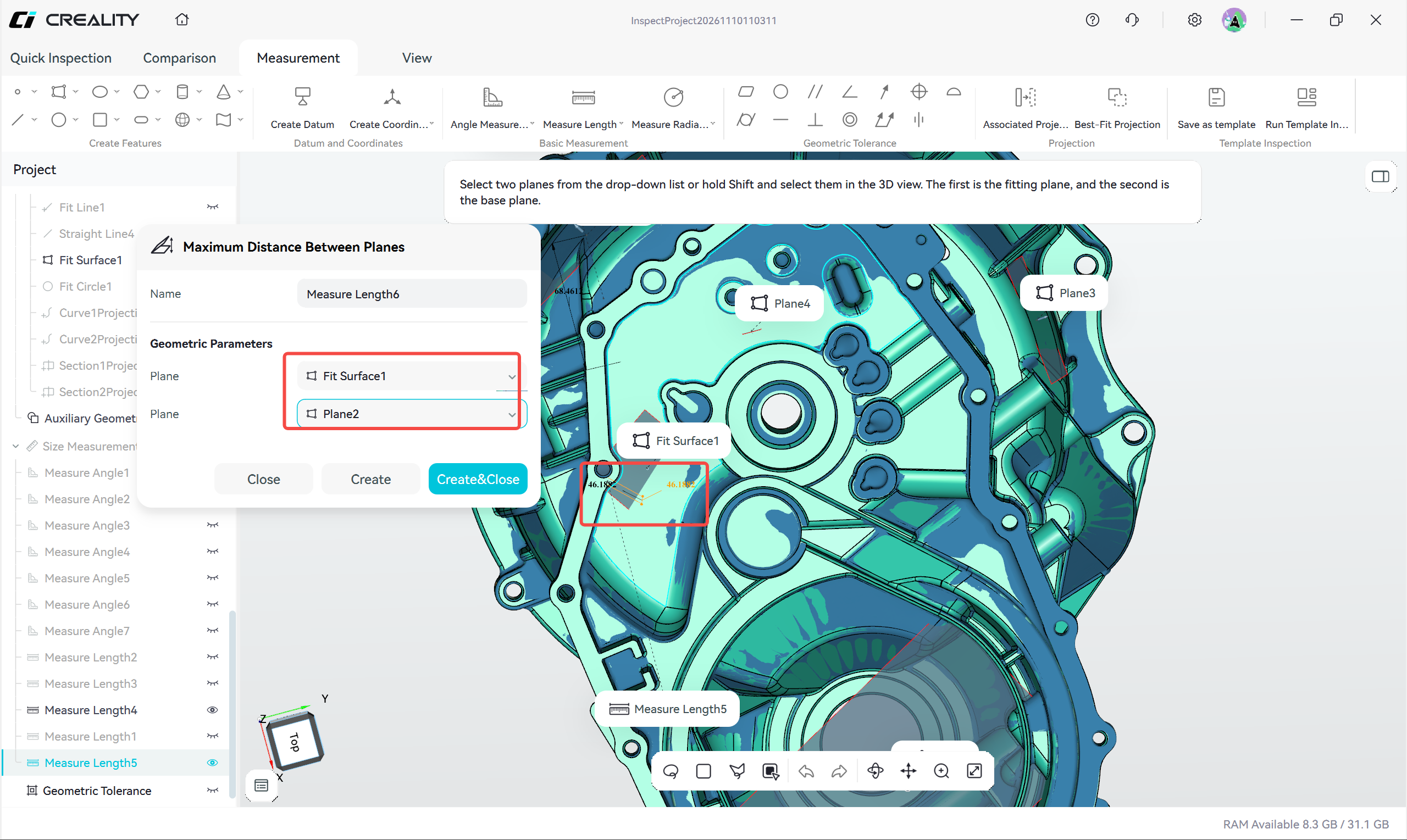
Caption: Figure 6-4-11 Maximum Distance Between Planes
6.4.3 Measure Radial Distance
Measures the radius or diameter of circle, sphere, and cylinder features
Click the Measure Radial Distance drop-down and select one of the following methods according to the measured feature:
| Measurement Method | Measured Feature | Measurement Content |
|---|---|---|
| Circle Radial Measurement | Circle | Radius / diameter |
| Sphere Radial Measurement | Sphere | Radius / diameter |
| Cylindrical Radial Measurement | Cylinder | Radius / diameter |
- Click the Measure Radial Distance drop-down and select the method that matches the measured feature type
- Select the corresponding circle, sphere, or cylinder feature
- Select radius or diameter output
- View the measurement value
Notes for each method:
- Circle Radial Measurement: applicable to planar circles or cross-sectional circles
- Sphere Radial Measurement: applicable to spherical features; the result is the sphere radius or diameter
- Cylindrical Radial Measurement: applicable to cylindrical features. When only part of the cylinder is fitted or the scan data is incomplete, the diameter result is affected by fitting quality; confirm that the fitting region covers the complete cylindrical surface
Tip: measurement targets can be existing features, or point features created quickly with Shift during selection; see "Selecting Measurement Targets".
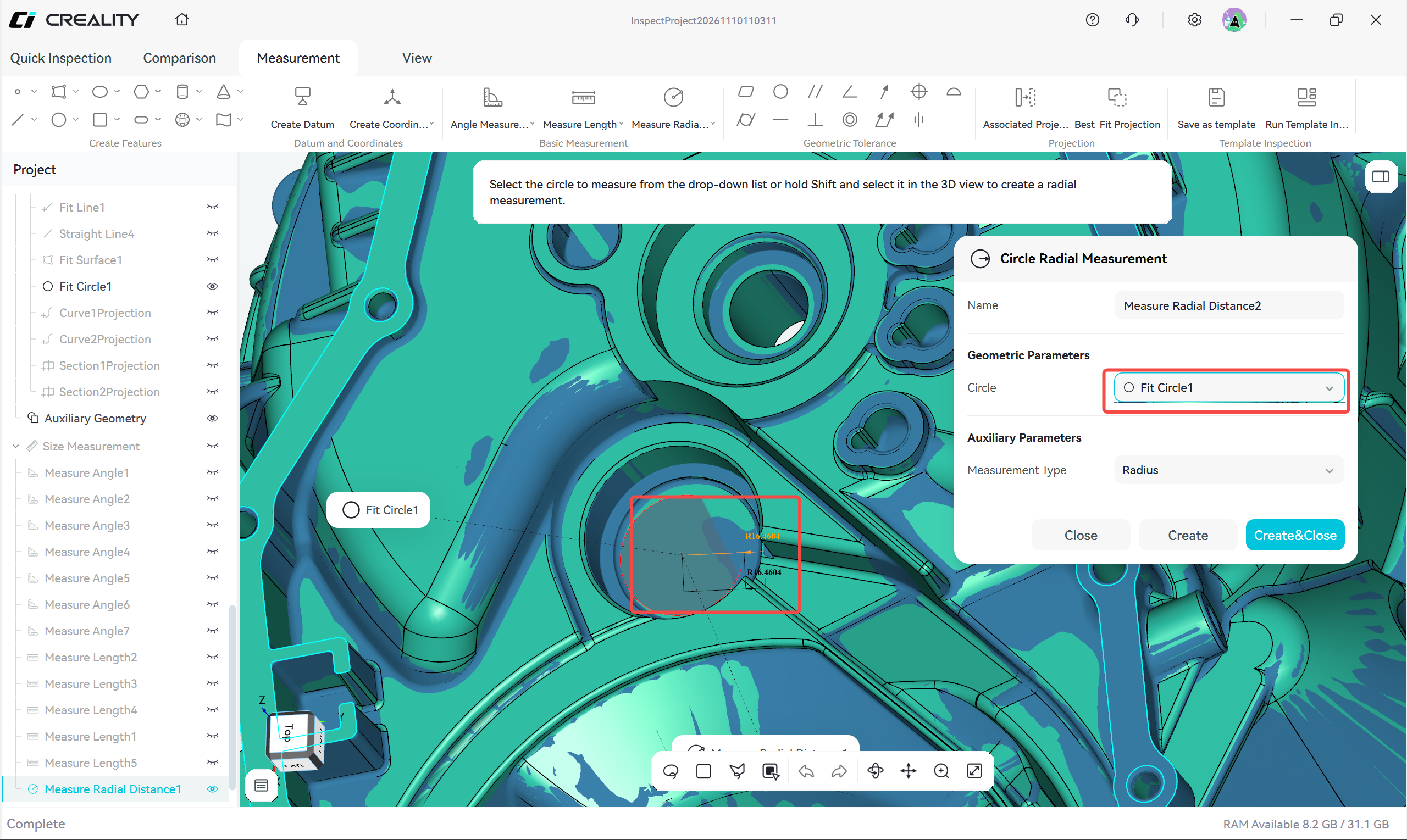
Caption: Figure 6-4-12 Circle Radial Measurement
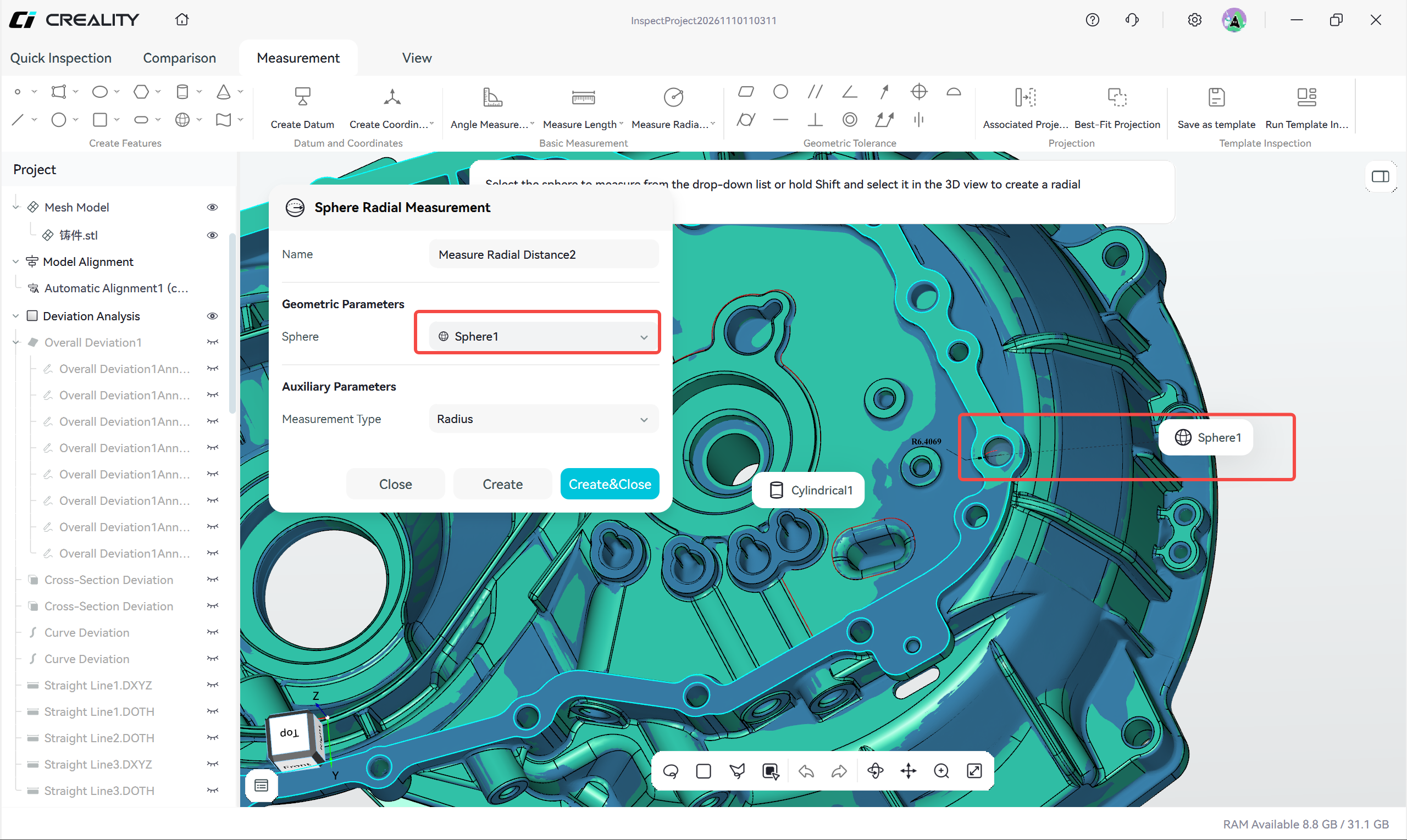
Caption: Figure 6-4-13 Sphere Radial Measurement
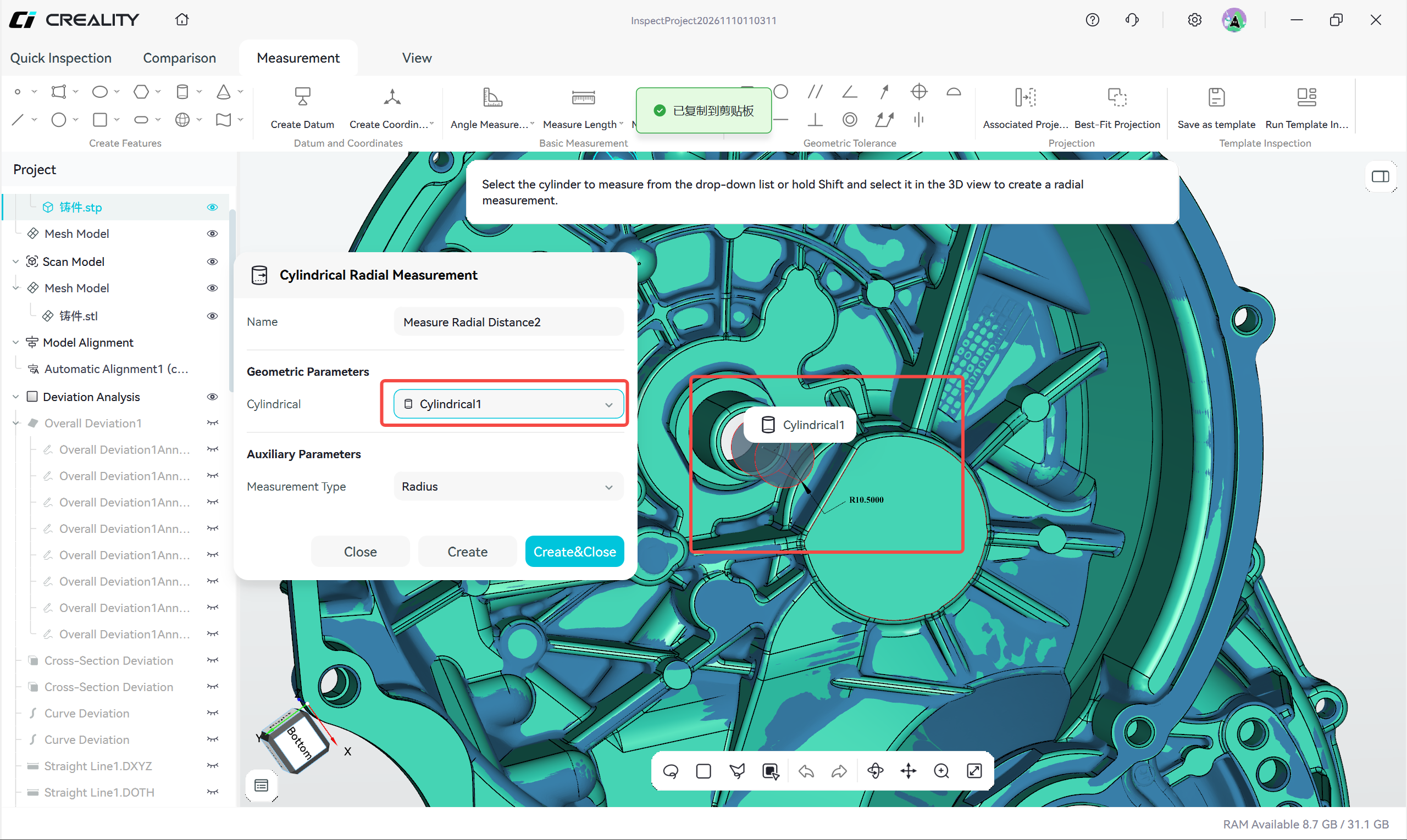
Caption: Figure 6-4-14 Cylindrical Radial Measurement
¶ 6.5 Geometric Tolerance
Uses existing geometric features to evaluate form, orientation, location, or runout deviations
Geometric tolerances include:
| Category | Tolerance |
|---|---|
| Form tolerance | Flatness, cylindricity, circularity, straightness |
| Orientation tolerance | Parallelism, perpendicularity, angularity |
| Location tolerance | Coaxiality, position, symmetry |
| Runout tolerance | Circular runout, total runout |
| Profile tolerance | Profile of a surface |
6.5.1 General Workflow
All tolerance dialogs share the same structure and are divided into the following areas:
| Area | Description |
|---|---|
| Name | Tolerance name; automatically numbered as "tolerance name + serial number" by default and editable |
| Geometric Parameters | Select the measured feature, scan model, datum (displayed only for tolerances that require a datum), and direction (optional) |
| Auxiliary Parameters | Tolerance value, i.e., the tolerance zone width |
| Text Parameters | Theoretical values such as design perspective, design size, and design radius; entity requirements; and the upper and lower limits of the dimensional tolerance. Provided only for some tolerances and used for annotations in the inspection report |
| Professional Parameters | Advanced options, collapsed by default |
Operation steps:
- Click the corresponding tolerance icon to open the dialog
- Rename the tolerance if necessary
- Select the measured feature
- Select the scan model
- For tolerances that require a datum, select the datum; set the direction when available
- Set the tolerance value
- Fill in the theoretical values (design perspective, design size, etc.) and the upper and lower limits of the dimensional tolerance as required
- Click Create to complete the current creation and continue creating, or click Create&Close to create and close the dialog
¶ 6.5.2 Parameter Differences Between Tolerances
| Tolerance | Typical Measured Feature | Datum | Specific Parameters |
|---|---|---|---|
| Flatness | Plane | Not required | — |
| Straightness | Line or axis | Not required | Calculation type: axis straightness / plain line straightness |
| Circularity | Circle or cylinder cross-section | Not required | — |
| Cylindricity | Cylinder | Not required | — |
| Profile of a Surface | Surface | Not required | — |
| Parallelism | Plane, line, or axis | Required | — |
| Perpendicularity | Plane, line, or axis | Required | — |
| Angularity | Plane, line, or axis | Required | Design perspective |
| Position | Point, circle, slot, or axis | Required | Design size |
| Coaxiality | Axis | Required | — |
| Symmetry | Center plane or center line | Required | — |
| Circular Runout | Surface of revolution | Required | — |
| Total Runout | Surface of revolution | Required | — |
Apart from the differences listed above, the dialog fields and operation steps of each tolerance are identical to the general workflow.
6.5.3 Key Points
- Measured features and datums must be created beforehand through Create Features and Create Datum; features on the scan model can be created in Fit mode
- Orientation tolerances (parallelism, perpendicularity, angularity), location tolerances (position, coaxiality, symmetry), and runout tolerances require a datum; otherwise they cannot be created
- Theoretical values (design perspective, design size, design radius) define the ideal position of the measured element and must be filled in according to the drawing
- The upper and lower limits of the dimensional tolerance define the acceptable dimensional range shown in the inspection report and are a different judgment condition from the tolerance value (the geometric tolerance zone)
6.5.4 Flatness
Checks the flatness of a planar surface
- Measured feature: plane; no datum required
- Typical use: flatness inspection of flange sealing faces, mounting surfaces, and joint faces
- Key point: when selecting a fitted plane, cover the complete measured surface as far as possible; incomplete scan data or noise directly amplifies the flatness error — adjust the selection and fit again if necessary
6.5.5 Cylindricity
Checks the form deviation of the entire cylindrical surface
- Measured feature: cylinder; no datum required
- Typical use: cylindricity inspection of shaft parts and hole features
- Key point: cylindricity is the most sensitive to fitting quality — the selection should cover the complete cylindrical surface and avoid a narrow strip only; results may be clearly distorted when the scan data is incomplete
6.5.6 Circularity
Checks whether the circular profile is close to a true circle
- Measured feature: circle or cylinder cross-section circle; no datum required
- Typical use: circularity inspection of bearing seats and sealing groove cross-sections
- Key point: when fitting a circle, the selection should lie on the same cross-section; selecting across sections introduces additional form error
6.5.7 Straightness
Checks the bending deviation of a line or axis
- Measured feature: line or axis; no datum required
- Specific parameter: the calculation type is either axis straightness or plain line straightness, selected according to the inspection requirement
- Typical use: straightness inspection of guide rails and long shaft axes
- Key point: for axis straightness, the measured feature should be a fitted axis; for plain line straightness, the selection should follow the direction of the generatrix
6.5.8 Parallelism
Checks whether the measured feature remains parallel to the reference datum
- Measured feature: plane, line, or axis; datum required
- Typical use: parallelism inspection of a slider guide surface relative to a rail datum plane
- Key point: create the datum in Create Datum first; the geometric types of the measured feature and the datum should match (plane to plane, line to line)
6.5.9 Perpendicularity
Checks whether the measured feature remains perpendicular to the reference datum
- Measured feature: plane, line, or axis; datum required
- Typical use: perpendicularity inspection of a mounting face relative to a base plane
- Key point: the direction setting affects the distribution direction of the tolerance zone; specify the direction when necessary. If the result is abnormal, check the datum selection and direction setting first
6.5.10 Angularity
Checks the orientation deviation between the measured feature and the reference datum
- Measured feature: plane, line, or axis; datum required
- Specific parameter: design perspective, filled in according to the angle on the drawing
- Typical use: angular deviation inspection of inclined surfaces and inclined holes relative to a datum plane or datum axis
- Key point: the design perspective is the ideal angle between the measured element and the datum and must be filled in according to the drawing; the tolerance value defines the allowable deviation from this angle
6.5.11 Coaxiality
Checks whether the measured axis and the reference axis remain on the same center axis
- Measured feature: axis; datum required
- Typical use: coaxiality inspection between shaft sections of a stepped shaft and within flange hole groups
- Key point: both the measured axis and the datum axis must be obtained from features such as fitted cylinders; the fitting region should cover the complete surface of revolution, otherwise the axis orientation deviation affects the evaluation result
6.5.12 Position
Checks the deviation of the measured feature from its theoretical position
- Measured feature: point, circle, slot, or axis; datum required
- Specific parameter: design size, i.e., the theoretical position parameter of the measured element
- Typical use: position inspection of hole groups and mounting holes relative to the datum system
- Key point: fill in the design size according to the drawing; when multiple datums are required, select the primary, secondary, and tertiary datums in the drawing order
6.5.13 Symmetry
Checks whether the measured feature remains symmetric about the reference center plane or center line
- Measured feature: center plane or center line; datum required
- Typical use: symmetry inspection of keyways and symmetric structures
- Key point: a center plane or center line feature must be constructed first (it can be constructed from existing features using other creation modes)
6.5.14 Circular Runout
Checks the runout deviation of a single cross-section of a surface of revolution relative to the datum axis
- Measured feature: surface of revolution (cylinder, cone, revolved surface); datum (datum axis) required
- Typical use: radial runout inspection of a single cross-section of shaft parts
- Key point: create the datum axis first; each cross-section must be evaluated separately — use Total Runout for overall runout evaluation
6.5.15 Total Runout
Checks the overall runout deviation of a surface of revolution relative to the datum axis
- Measured feature: surface of revolution (cylinder, cone, revolved surface); datum (datum axis) required
- Typical use: overall runout inspection of the entire cylindrical surface of shaft parts relative to the datum axis
- Key point: the difference from circular runout is the evaluation scope — total runout evaluates the entire surface rather than a single cross-section; the more complete the fitting region, the more accurately the result reflects the true runout
6.5.16 Profile of a Surface
Checks the deviation between the actual surface and the reference shape
- Measured feature: surface
- Typical use: profile deviation inspection of free-form surfaces and molded surfaces relative to the theoretical CAD surface
- Key point: the measured surface should be obtained from scan data in Fit mode, and the selection must cover the complete profile surface; the result can be read together with the overall deviation color map
¶ 6.6 Projection
Projects features from the reference model onto the scan model to establish the correspondence between reference features and scan features
Projection solves the following problem: a one-to-one association must be established between a reference feature (a point, line, or plane on the CAD model) and the actual surface of the scan model so that RPS Alignment, Dimensional Deviation, and other functions can reference the feature pair. The software provides two projection methods:
| Projection Method | Source of the Scan Feature | Applicability |
|---|---|---|
| Associated Projection | The user has already created the feature on the scan model and specifies the correspondence during projection | Fitted features are already available on the scan model, or the correspondence must be controlled precisely |
| Best-Fit Projection | The software automatically fits and generates the feature on the scan data from the reference feature | Only the reference model needs features; manual operations should be minimized for efficiency |
Common prerequisites for both methods:
- Model alignment is complete — the projection result depends on alignment accuracy, and alignment deviations are passed directly to the projected features
- The reference feature has been created on the reference model (in CAD mode)
- For Associated Projection, the corresponding scan feature has also been created on the scan model in advance (in Fit mode)
6.6.1 Associated Projection
Associates a reference feature with an existing corresponding feature on the scan model
Dialog parameters:
| Parameter | Description |
|---|---|
| Name | Projection name; automatically numbered as "Associated Projection + serial number" by default and editable |
| Reference Geometry | Select the reference feature on the reference model |
| Scan Geometry | Select the corresponding feature already created on the scan model |
Operation steps:
- Complete model alignment
- Create the reference feature on the reference model in CAD mode
- Create the corresponding scan feature on the scan model in Fit mode
- Click Associated Projection to open the dialog
- Select the reference feature
- Select the scan feature
- Click Create to complete the current creation and continue creating, or click Create&Close to create and close the dialog
- Check the projection result in the project tree
Key points:
- The reference feature and the scan feature must be located at the same structural position of the part and must be of the same geometric type (line to line, circle to circle, plane to plane)
- Associated Projection does not refit the scan feature; the quality of the scan feature depends on the earlier fitting selection. If the fit is inaccurate, correct the scan feature first and then associate again
- If the two features are of mismatched types or their positions deviate too much, the association cannot be established
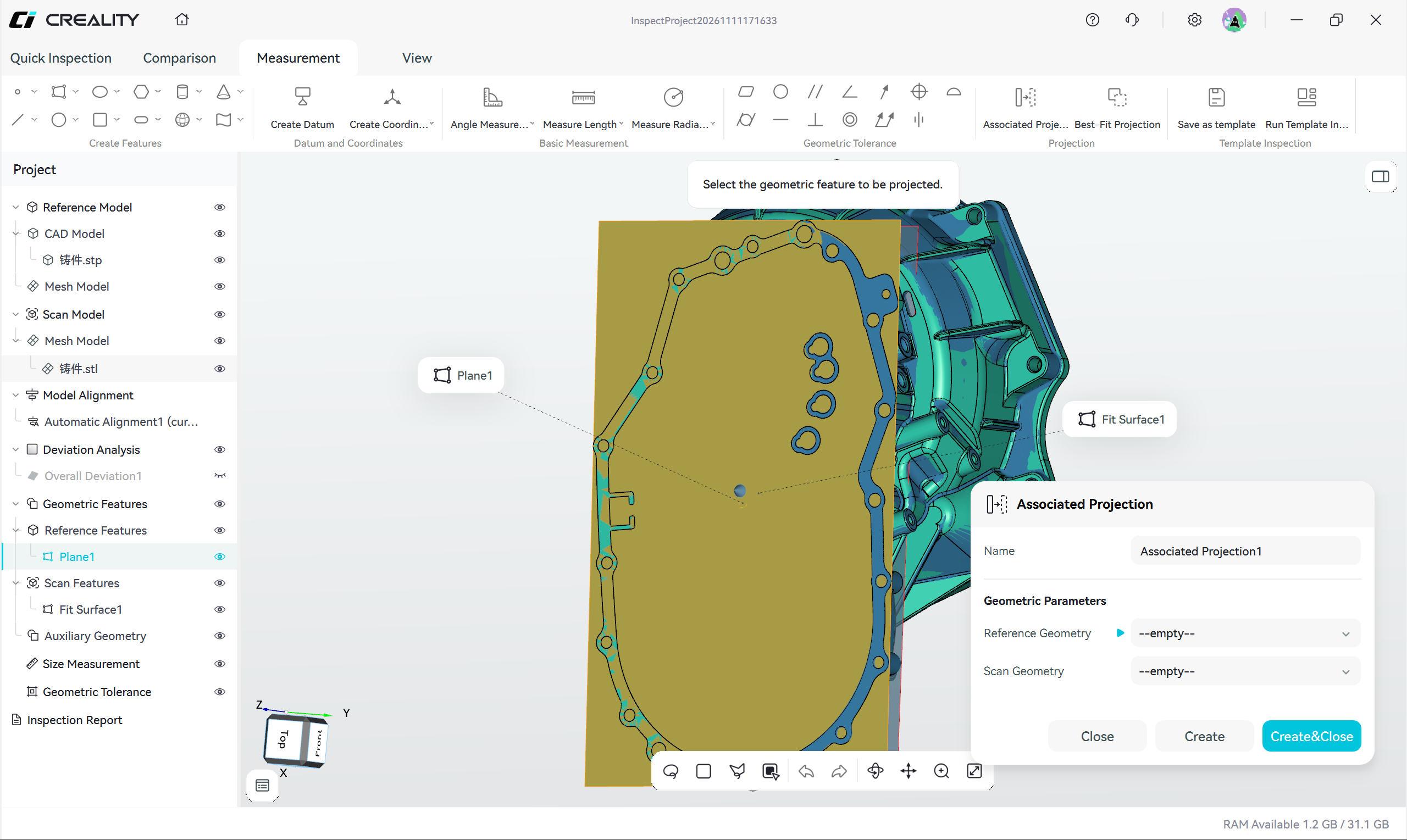
Caption: Figure 6-6-1 Construct a plane feature on the reference model
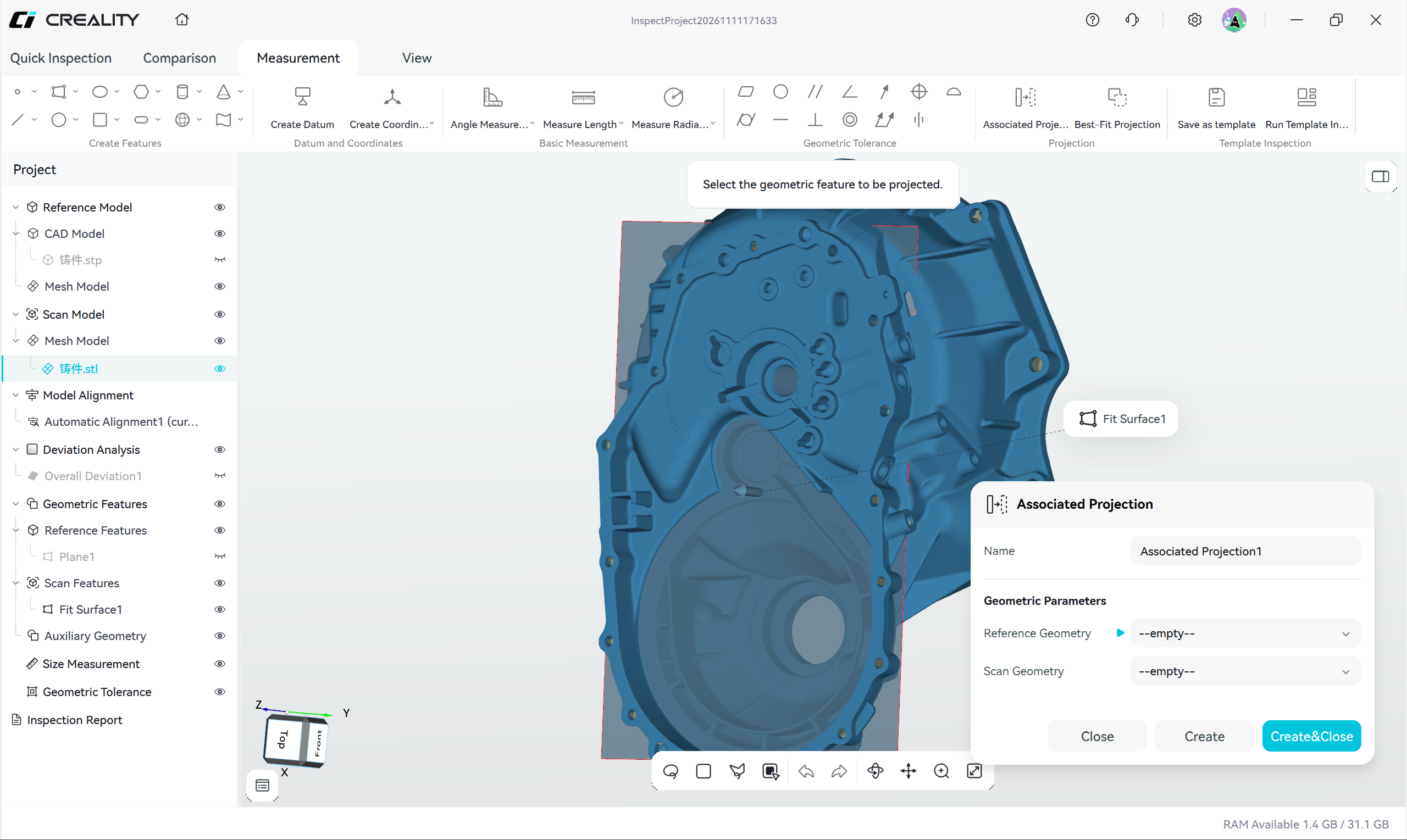
Caption: Figure 6-6-2 Construct a plane feature on the scan model
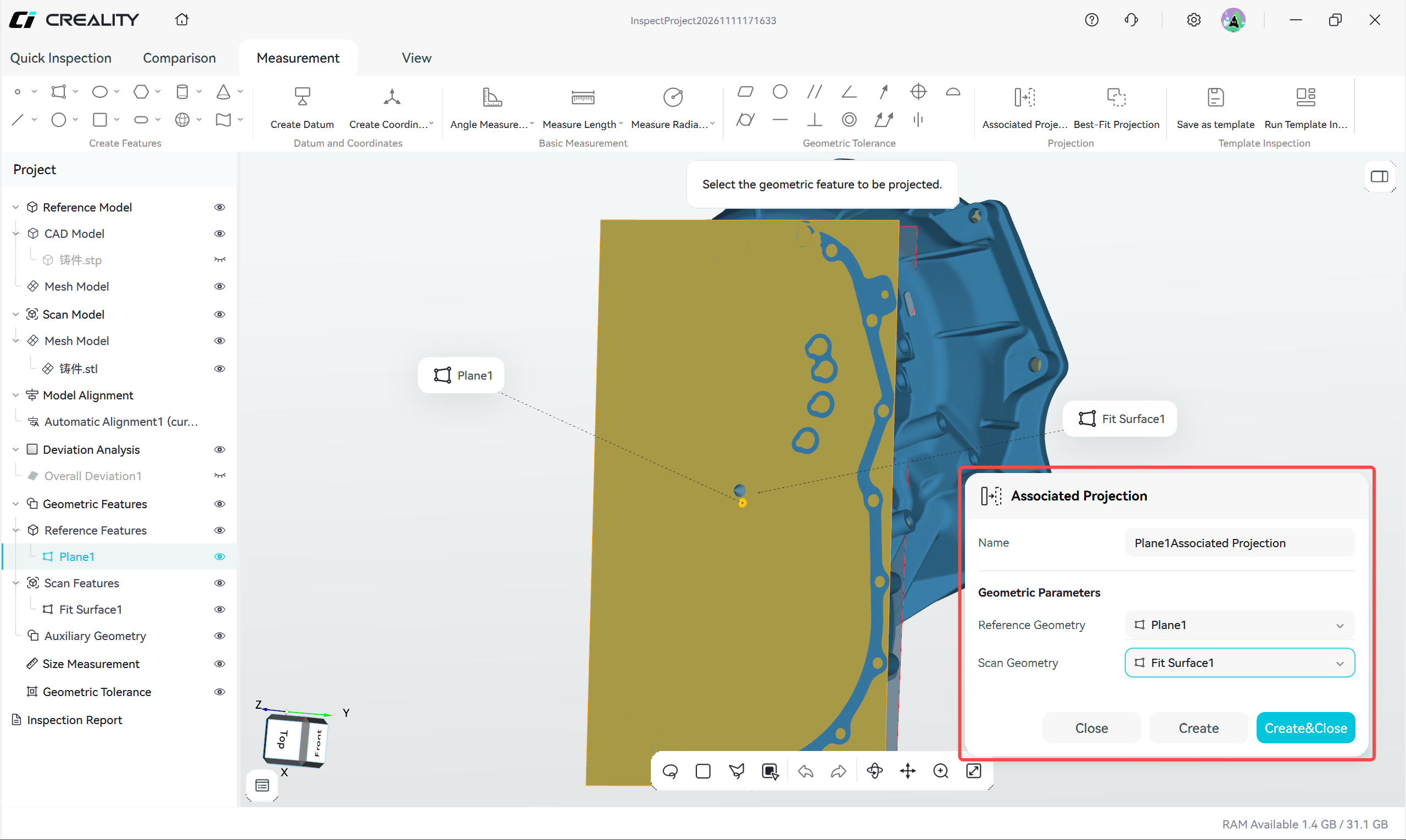
Caption: Figure 6-6-3 Select the two features to be associated
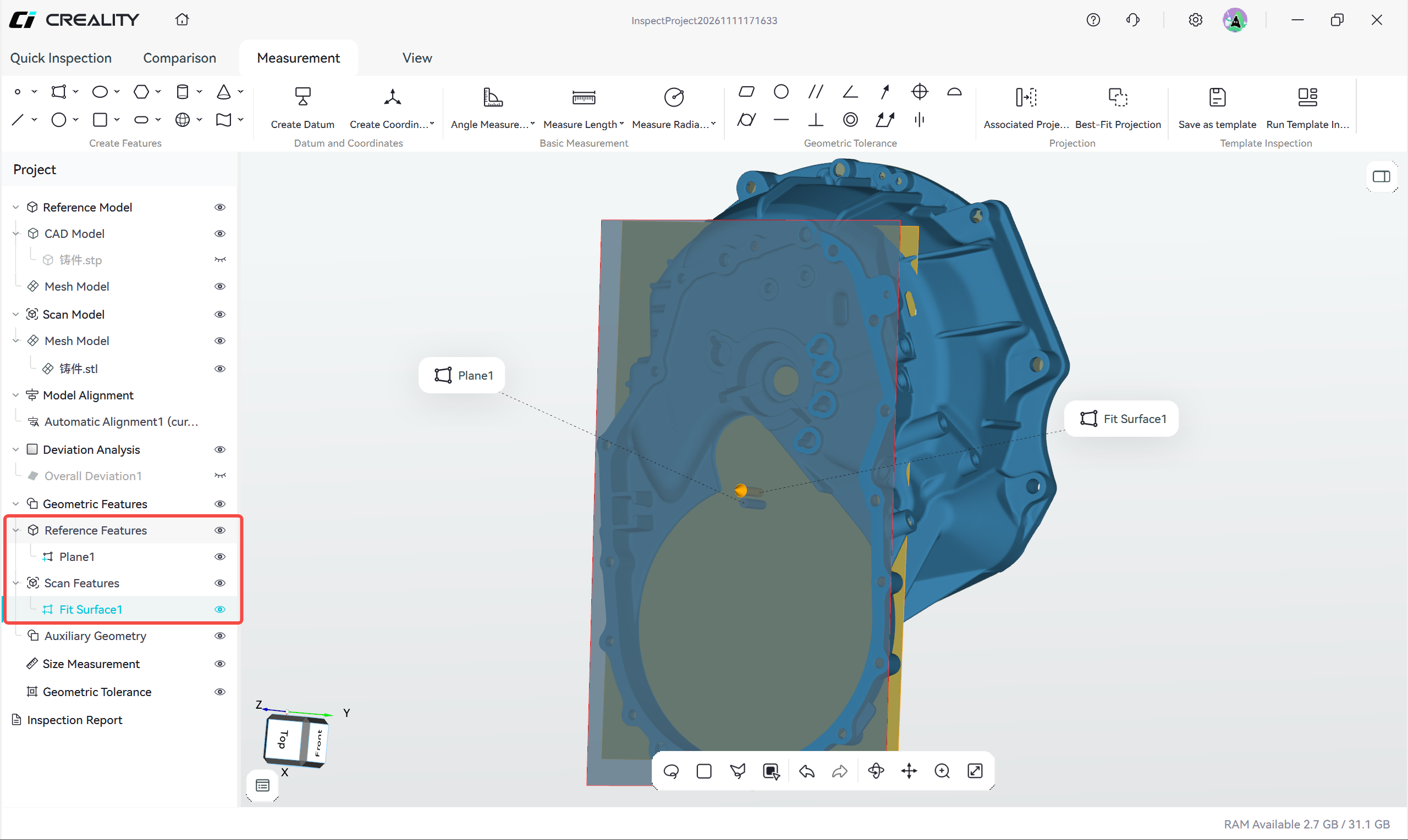
Caption: Figure 6-6-4 Result after associated projection
6.6.2 Best-Fit Projection
Projects the reference feature onto the scan model and automatically fits the corresponding scan feature
Dialog parameters:
| Parameter | Description |
|---|---|
| Name | Projection name; automatically numbered as "Best-Fit Projection + serial number" by default and editable |
| Reference Geometry | Select the reference feature on the reference model |
| Scan Model | Select the scan model |
| Use fixed distance | When selected, the fitting search range is limited to a fixed distance, and the distance value is entered on the right; when cleared, the software determines the search range automatically |
| Maximum Normal Vector Angle | The maximum deviation angle allowed between the normal of the scan surface participating in the fit and the normal of the reference feature; the default is 20° |
Operation steps:
- Complete model alignment
- Create the reference feature on the reference model in CAD mode
- Click Best-Fit Projection to open the dialog
- Select the reference feature
- Select the scan model
- Select Use fixed distance and set the distance value as needed, or adjust Maximum Normal Vector Angle
- Click Create to complete the current creation and continue creating, or click Create&Close to create and close the dialog
- Check the automatically generated scan feature and confirm that its position, orientation, and size are as expected
Key points:
- After selecting Use fixed distance, a distance value that is too small may miss the actual surface, while a value that is too large may include adjacent structures in the fit; clear the option if the position accuracy is reliable
- Maximum Normal Vector Angle filters out scan surfaces whose orientation deviates too much from the reference feature, preventing the fit from locking onto adjacent inclined surfaces; if the result leans toward a neighboring structure, reduce the angle
- The fitted scan feature is listed under Geometric Features in the project tree and can be referenced by later inspections like a manually created feature
- If the fitting result is unsatisfactory, adjust the parameters above and run Best-Fit Projection again
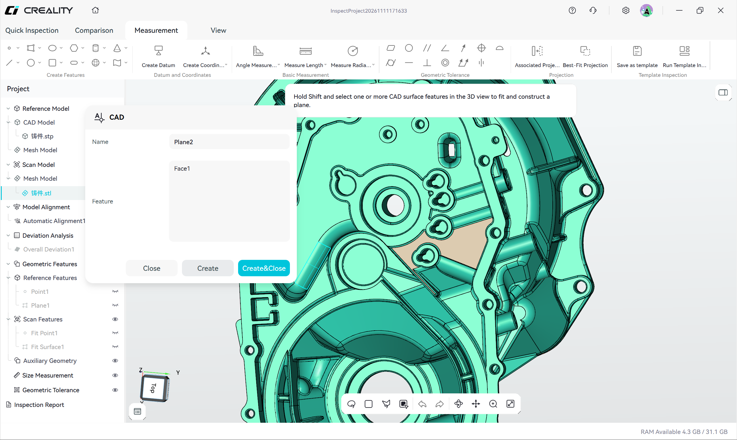
Caption: Figure 6-6-5 Create a feature on the reference model
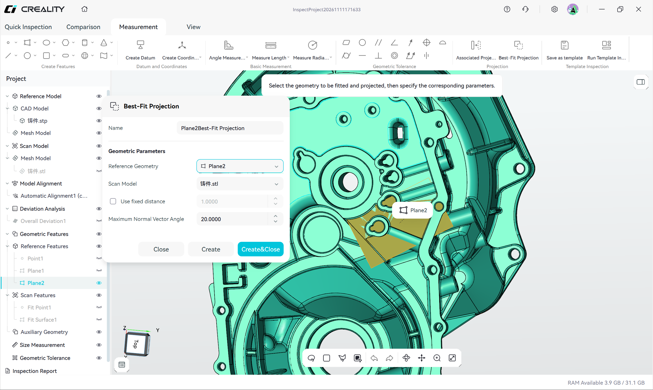
Caption: Figure 6-6-6 Select the feature for Best-Fit Projection
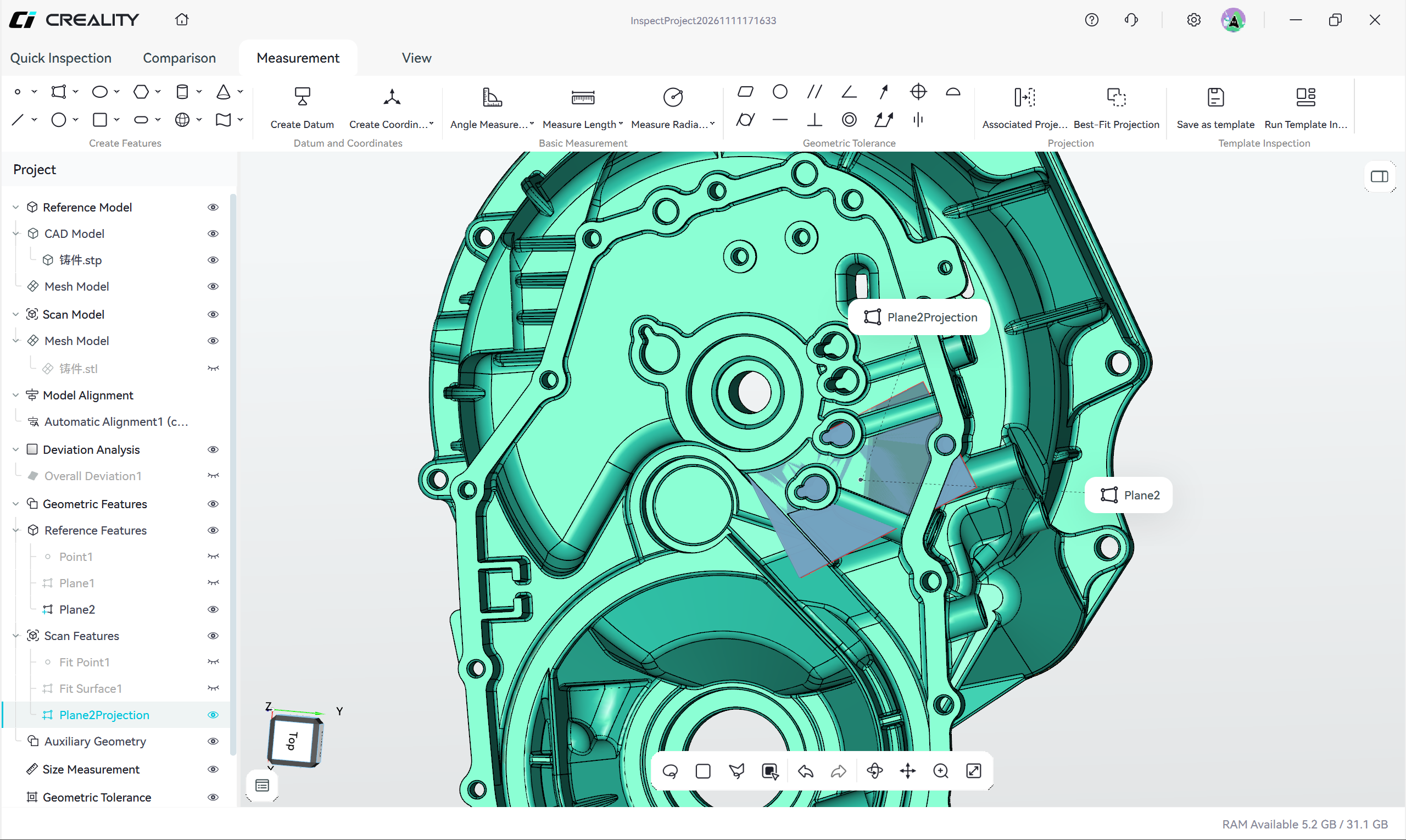
Caption: Figure 6-6-7 Result after best-fit projection
6.6.3 Managing and Using Projection Results
After projection, an association is formed between the reference feature and the scan feature. It can be used for:
- RPS Alignment — optimizing the model alignment result by constraining the associated features
- Dimensional Deviation — selecting the associated feature pair directly and comparing the nominal and actual values
- Geometric tolerance — using the projected scan feature as the measured feature
Maintaining the projection relation:
- Projection results are displayed in the project tree and can be hidden or deleted individually
- Deleting a projection only removes the association between the two features; the features themselves are not deleted
- After a projection is removed or modified, the alignments and inspections that reference it must be re-executed
- After model alignment is adjusted or the scan feature is refitted, the existing projection relation may become invalid and must be re-projected
6.7 Template Inspection
Saves a completed inspection workflow as a template and automatically runs the same inspection on parts of the same type
Template Inspection is intended for repeatedly running the same inspection workflow on parts of the same type. After the first inspection is complete, save the model alignment, geometric features, projections, measurements, and geometric tolerances as a template; when inspecting a new part of the same type, run Template Inspection to reproduce the entire workflow automatically without repeating each step.
Template Inspection includes two functions:
| Function | Purpose | When to Use |
|---|---|---|
| Save as Template | Saves the inspection content of the current project as a template file | After the first inspection is complete and all inspection content is confirmed |
| Template Inspection | Creates a new project and runs the inspection automatically with the template | When inspecting a new part of the same type |
6.7.1 Save as Template
Saves the completed inspection content of the current project as a reusable template file
Dialog parameters:
| Parameter | Description |
|---|---|
| Path | Save path of the template file; defaults to the temporary folder in the software installation directory and can be changed by clicking the folder icon on the right |
| Name | Template name; must be entered manually |
Operation steps:
- Complete the first inspection and confirm that the model alignment, geometric features, projections, measurements, and geometric tolerances are complete
- Click Save as Template
- Set the template save path
- Enter the template name
- Click OK to save
Key points:
- Confirm that the inspection content of the current project is complete before saving — unfinished inspection items have no results in the template, and no such results are produced when the template is applied
- Templates are related to the part type and structure; name templates after the part for easier retrieval
- The default path is located in the software installation directory. Change it to a dedicated data directory to manage template files centrally and avoid losing them when the software is updated or uninstalled
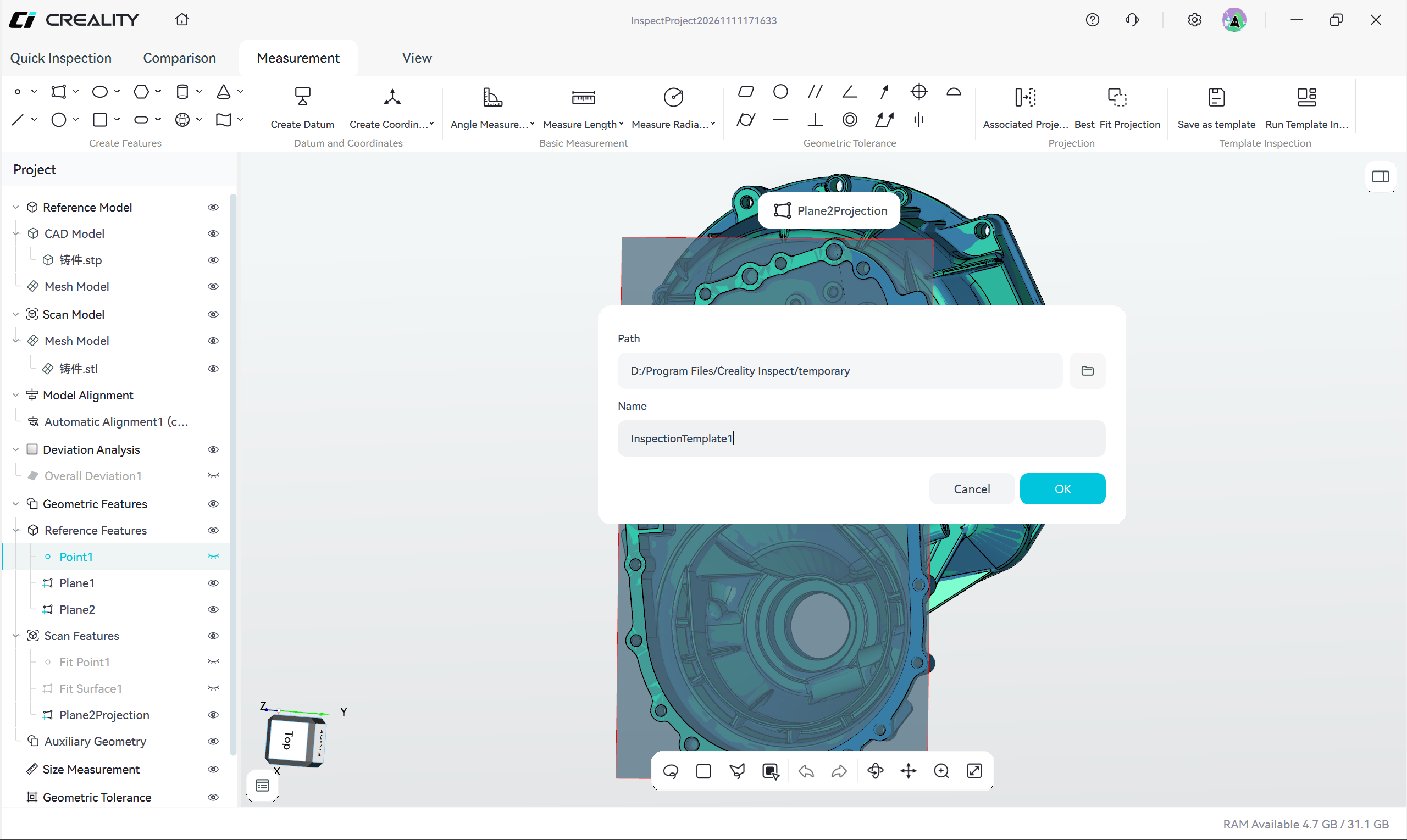
Caption: Figure 6-7-1 Save inspection template
6.7.2 Template Inspection
Creates a new inspection project, selects the inspection template and the detected model, and automatically runs the inspection workflow in the template
After you click Template Inspection, the software prompts you to save the current project first, then creates a new project and enters the template inspection workflow.
Dialog parameters:
| Parameter | Description |
|---|---|
| Inspection Template | Select the saved template file |
| Detected Model | Select the scan model for this inspection |
Operation steps:
- Click Template Inspection
- Save the current project as prompted
- The software creates a new inspection project and opens the Template Inspection dialog
- Select the inspection template
- Select the detected model
- Click Start to run
- Wait for the inspection to complete
- Check for unassociated or failed inspection items
- View the inspection results and, if necessary, complete or correct them before generating a report
Key points:
- The template must match the type and structure of the part being inspected; otherwise the features in the template may not be located or fitted on the new scan model
- The position and orientation of the scan model should be as close as possible to those used when the template was created to improve the success rate of automatic inspection
- After the inspection is complete, verify the results item by item and correct failed or clearly abnormal items manually
- The Inspection Template and Detected Model must both be specified before running; the Start button becomes available once both are filled in
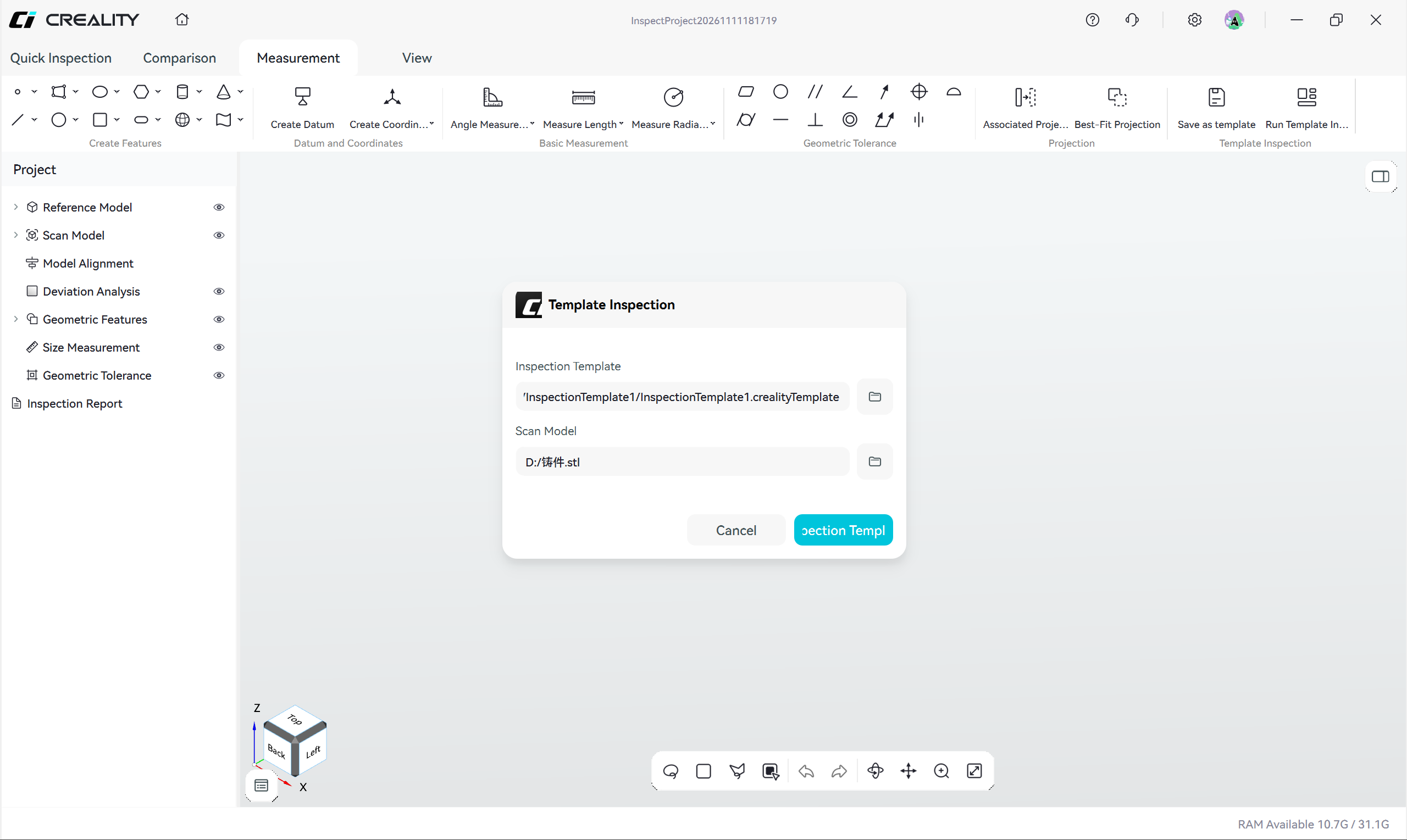
Caption: Figure 6-7-2 Import the inspection template and model
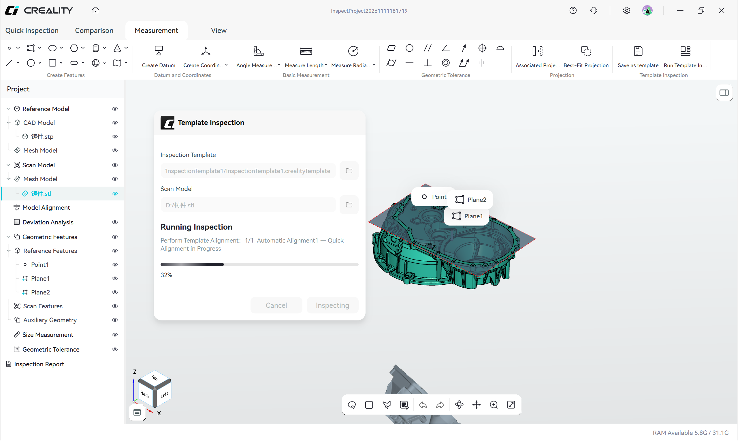
Caption: Figure 6-7-3 Run template inspection
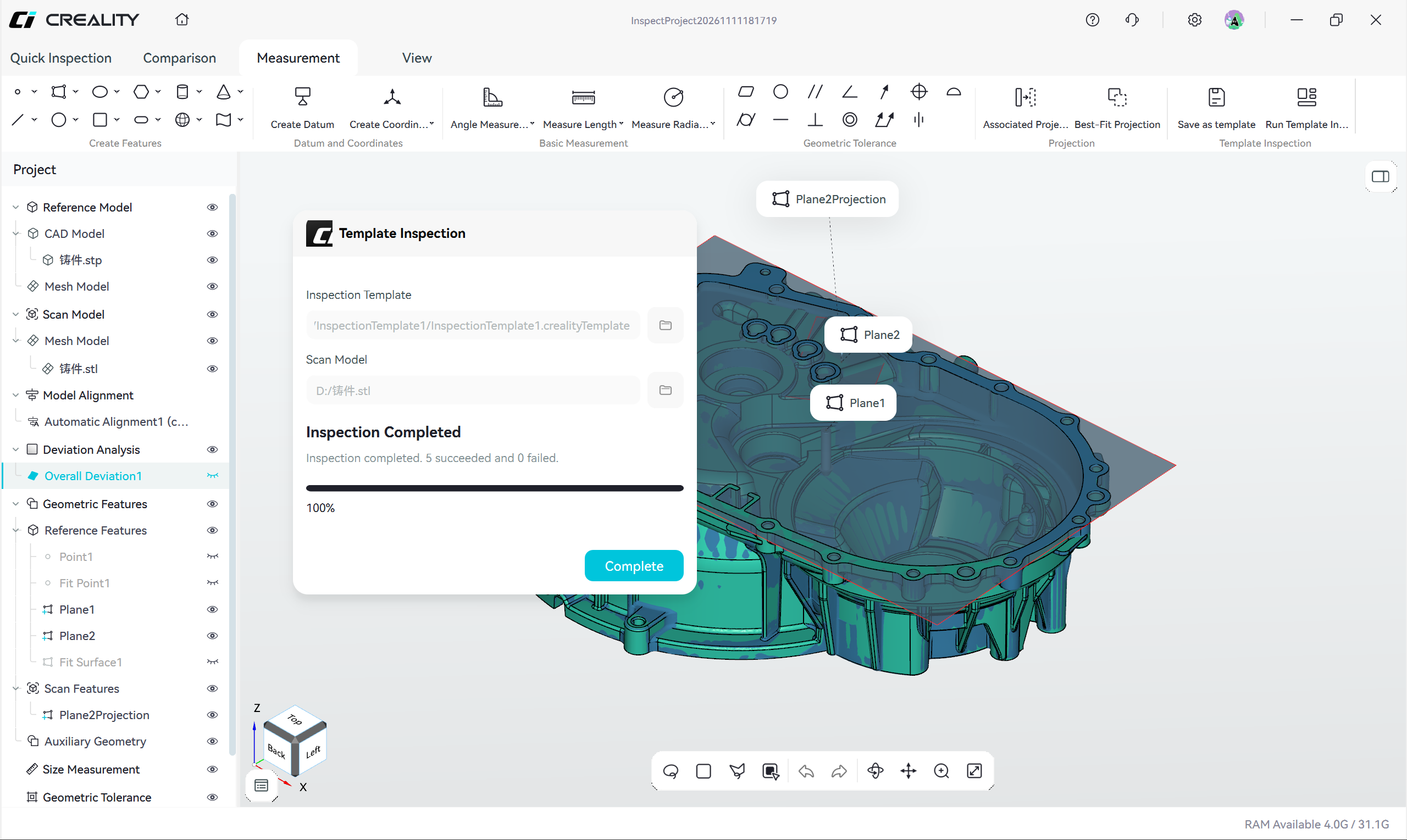
Caption: Figure 6-7-4 Template inspection completed
6.7.3 Applicability of Template Inspection
Scenarios suitable for templates:
- Batch inspection of parts of the same model — for example, parts machined in batches from the same drawing
- Periodic inspection with a fixed workflow — for example, the same sampling items for each batch
Scenarios not suitable for templates:
- When part structures differ significantly, the features in the template cannot be matched and manual inspection must be performed again
- When the first inspection workflow has not been validated — save it as a template only after confirming that the first inspection result is correct
¶ 7 Generate Report
Organizes inspection results, fills in report information, previews, and exports the inspection report
Report output includes two functions: Create Report Page organizes inspection results into image-and-table pages, and Generate Report consolidates the content and exports it.
| Function | Purpose |
|---|---|
| Create Report Page | Selects inspection results and generates report pages containing images and tables; multiple pages can be created |
| Generate Report | Fills in report information, selects report content, previews, and exports |
¶ 7.1 Create Report Page
Operation steps:
- Click Create Report Page
- Rename the report page
- Select the content format: Image, Table (both can be selected)
- In Scan Data, select the inspection data to present and move it to Select data
- Click OK to complete the creation
The report page is listed under Inspection Report in the project tree and can be deleted and recreated.
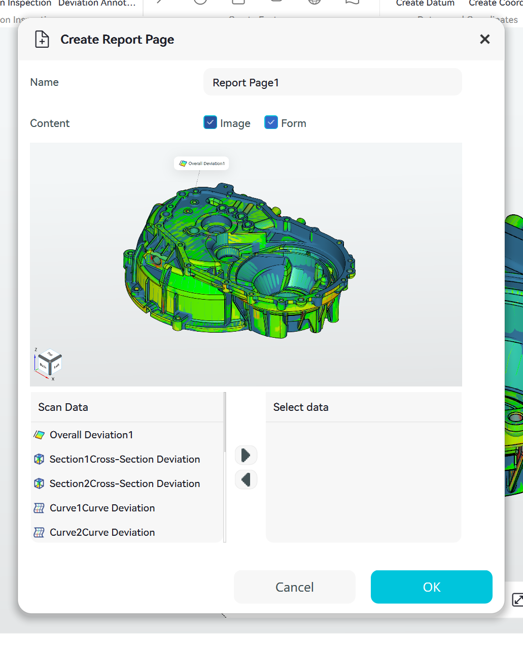
Caption: Figure 7-1 Create Report Page
¶ 7.2 Generate Report
Operation steps:
- Click Generate Report
- Fill in the report information: Title, Company, Department, Location, Project, Part, Date, and Inspector
- To use a company logo, click Upload Logo (PNG, JPG, or JPEG, up to 5 MB; optional)
- In Scan Data, select the content to include in the report and move it to Select data
- Click Preview to check the preview, then click OK to complete and export
The report content usually includes the reference model, scan model, model alignment result, deviation analysis, and created report pages.
The report is exported as a PDF file; select the save location and enter a file name when exporting.
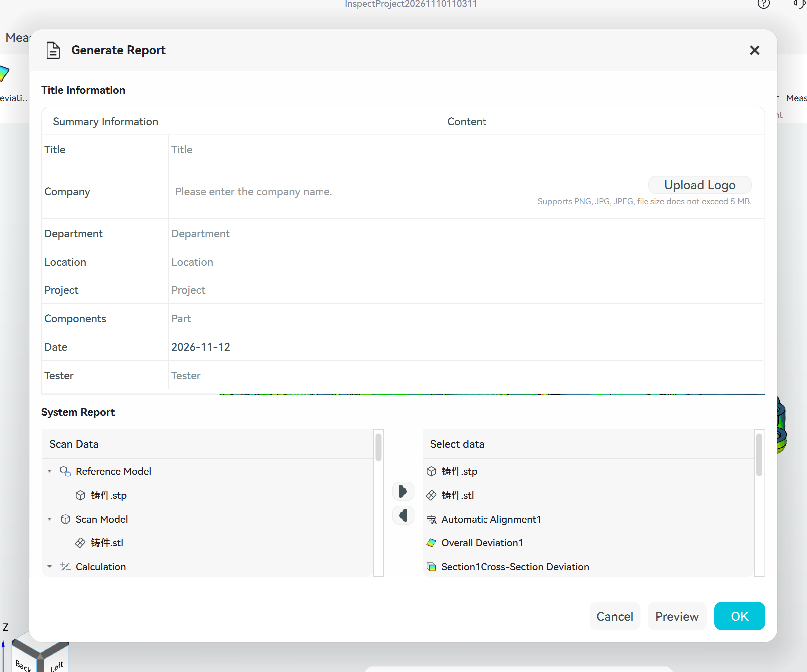
Caption: Figure 7-2 Generate Report
¶ 8 Project Management
¶ 8.1 View Object Properties
View the name, type, and geometric parameters of the currently selected object.
Operation steps:
- Select a model, feature, or inspection item
- View the corresponding property panel
¶ 8.2 View Inspection Results
View the measured value, tolerance, and judgment result of the currently selected inspection item.
Operation steps:
- Select the inspection item to view
- View the corresponding inspection data
- Check the deviation value, tolerance, and pass/fail status
Different inspection types can display different fields, for example:
- Nominal value
- Actual value
- Deviation
- Tolerance upper limit
- Tolerance lower limit
- Maximum value
- Minimum value
- Average value
- RMS
- Standard deviation
- Inspection result
The inspection results area shows only the currently selected inspection item and does not merge results with different fields.
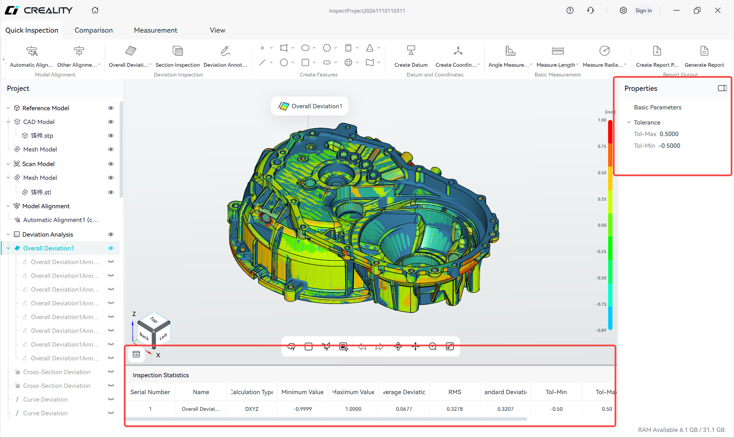
Caption: Figure 8-1 View object properties and inspection results
¶ 9 FAQ
Which purpose should I select when importing a mesh model?
Select Reference Model if the model represents the design standard or inspection datum; select Scan Model if the model comes from actual scan results.
What should I do if automatic alignment is incorrect?
Use Manual Alignment to select three corresponding points and establish the initial position, then run Automatic Alignment again. If only a local region is of interest, use Local Alignment.
Why can't I select objects in Datum Alignment?
Datum Alignment requires the corresponding geometric features and datums to be created in advance. Check whether usable features exist on both models.
Why can't Coordinate System Alignment be executed?
Confirm that coordinate systems have been created on both the reference model and the scan model, and check the origin and axis directions.
Why can't I select the required object when creating a feature?
The current feature may depend on other geometric features. Create the dependent features first, then perform the current operation.
Why can't the geometric tolerance be calculated?
Check the following:
- Whether the measured feature has been created
- Whether the measured feature type is correct
- Whether the current tolerance requires a datum
- Whether the theoretical values and tolerance are fully filled in
Why are not all inspection results displayed?
Different inspection types use different fields, so the results area shows only the currently selected inspection item. All inspection content can be organized and output through the inspection report.
How do I restore a hidden object?
Click the closed-eye icon next to the object, or select Show All.
How do I inspect parts of the same type repeatedly?
Save the completed inspection content as a template first. Next time, click Template Inspection, save the current project as prompted, select the inspection template and the detected model in the new project, and click Start.
Can I export a report without uploading a logo?
Yes. The logo is optional and does not affect report preview or export.