¶ Installation
¶ Software
https://www.crealitycloud.com/software-firmware/software/creality-scan
¶ Firmware
https://www.crealitycloud.com/software-firmware/other/type-26
(* Normally, you don't need to download the firmware manually. You can click Install in the prompt of the latest version of the software. Only if the installation fails, you need to try to install the firmware manually.)
¶ Windows 10/11 (64-bit)
Recommended configuration: CPU i7-Gen8 and above, Nvidia graphics card, 16GB RAM or above
Minimum configuration: CPU i5-Gen8 and above, 8GB RAM or above.
Software version: Creality Scan ≥ v3.1.22
¶ macOS
Recommended configuration: CPU Apple M1/M2/M3/M4 series processor, 16G RAM or above
System version macOS 11.7.7 and above (Big Sur/Monterey/Ventura)
Minimum configuration: CPU i5-Gen8 and above, 8GB RAM or higher.
System version macOS 10.15.7 and above (Catalina/Big Sur/Monterey/Ventura)
Software version: Creality Scan ≥ v3.1.22
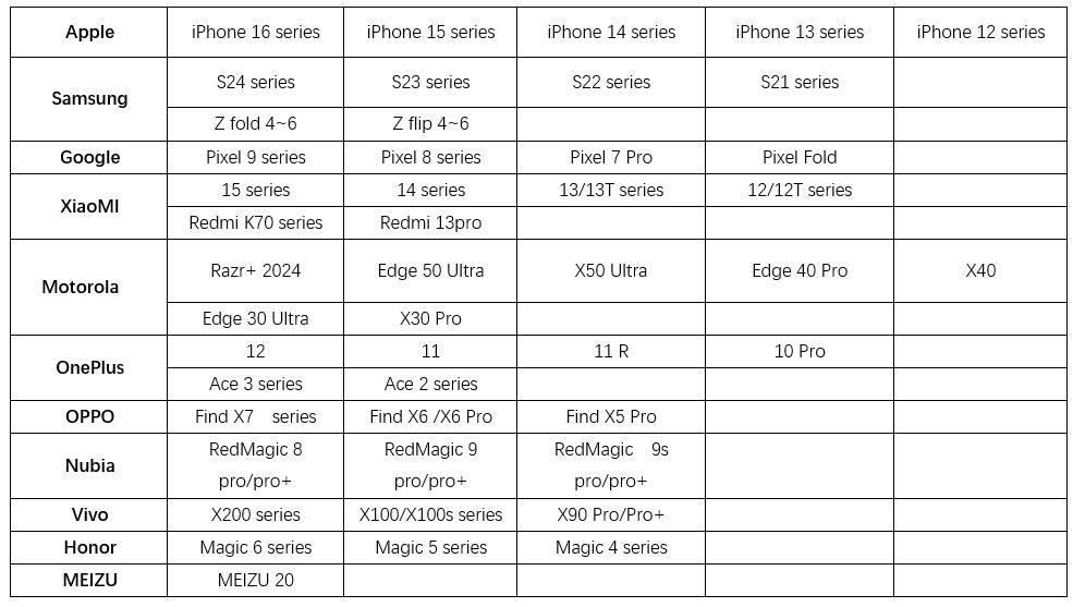
¶ Mobile Phone
Recommended moblie phone models(Same for RaptorX and Raptor pro)
(For iPhone, it recommend 16G RAM or above.)
¶ Windows & Mac software guidance
¶ Home page
.png)
Check if the scanner is connected successfully in the information panel on the left side of the homepage; It is recommended to use USB3.0 to connect the scanner. After connected the scanner, the information panel will display the basic device information and allow access to the calibration page.
① The left-side panel contains three entry points: Homepage, User Guide, and Discover.
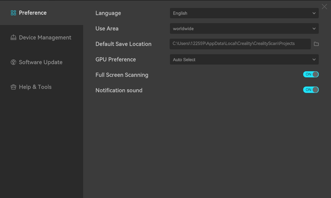
② The software setting window is set in the upper right corner, supporting functions such as language switching, performance testing, and full-screen scanning.
③ The middle panel displays a multi-project list for "Recent Projects". Click on the corresponding image to open the respective multi-project. The "Recycle Bin" allows you to restore or permanently delete projects, and the "Search Bar" enables you to search for existing projects.
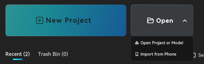
④ There are 3 ways to start the scanning poccess:
- Click "Create New Project" to start scanning;
- Click "Open" and select "Open Local Project" to import multi-projects (in .obp format) from local folders or view models (in .stl, .obj, or .ply formats);
- Click "Import from Mobile Phone" to import projects from the mobile app via the local area network (LAN). Note that the mobile phone and computer must be connected to the same LAN.
¶ Quick Calibration
Reference Videos:
Raptor series: https://www.youtube.com/watch?v=T1gTWuQRO-c
After the device is connected, enter through the calibration button in the left infobox of the homepage.
.png)
When using it for the first time, be sure to aim it at the back of the calibration board that comes with the package to scan the QR code.
.png)
After entering the acquisition process, be sure to aim the scanner at the front of the calibration board and move the scanner according to the guidance.
.png)
The left and right sides are process guidance areas, showing the pose and angle requirements for the current acquisition. Pay attention to matching the orientation of the scanner and calibration board according to the diagram. When placing the calibration board on the table, make sure the arrow is facing upwards.
.jpg)
The bottom left shows the calibration board number and scanner temperature. Please make sure to perform calibration within the appropriate temperature range. The rightmost side shows the current step.
The guidance areas are used to guide the scanner's pose in real time. As pose acquisition is completed, the corresponding steps on the right side illuminate one by one.
- The left guidance area primarily directs the scanner's forward, backward, left, and right movements.
- The right guidance area primarily guides the scanner's height adjustment.
During calibration, the scanner is moved to the target position according to the guidance, ensuring that the two scanner models overlap and pose acquisition is complete, as shown in the figure below.
.png)
After the current pose collection is completed, the system will automatically proceed to the next pose collection. Please move the scanner in accordance with the guidance repeatedly until all poses in the entire process are collected.
Once collection is finished, the system will automatically enter the calibration processing stage—please wait patiently for the calibration result. After successful calibration, please start scanning to experience high-quality scanning.
¶ Scan Settings
Click "New Project" on the homepage, as shown below:
.png)
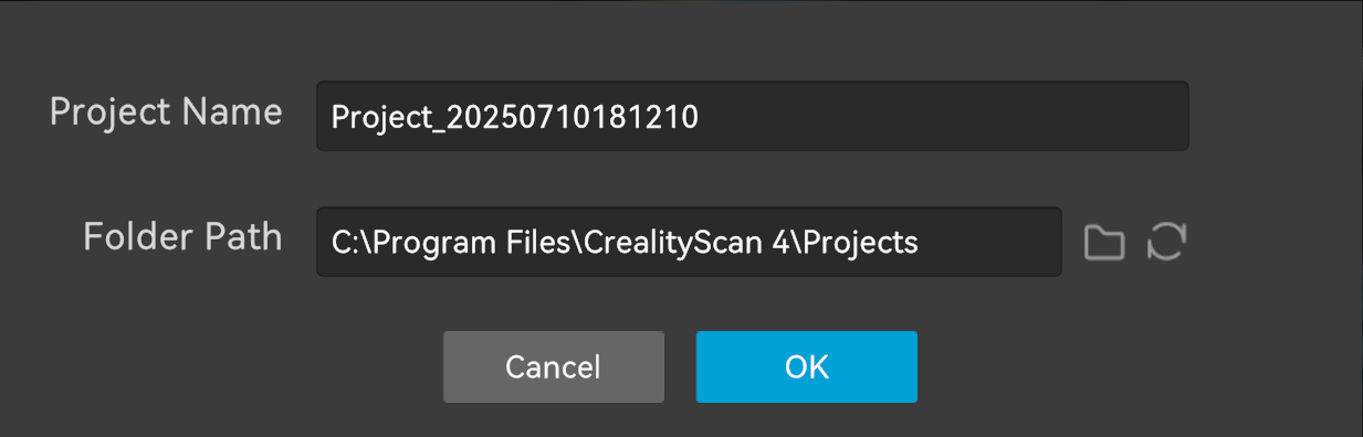
Enter the project name in the pop-up bar, select the folder path, and then click the "OK" button, as shown below:
It's recommended to use the name of the scanned object as the project name to improve recognition.
After clicking the page, you will enter the scanning settings page.
.png)
¶ Blue Laser Mode / Infrared Mode Selection
The scan mode is divided into "Blue Laser Mode" and "Infrared Mode".
- To choose between blue laser mode and infrared mode depends on specific scanning requirements and object characteristics.
- Generally speaking, blue laser mode is suitable for scanning objects with rich details and unusual surface materials. It is particularly suitable for industrial manufacturing and inspection scenarios where high precision is required and circular reflective markers are needed for scanning and tracking.
- Infrared mode is suitable for fast scanning and supports geometry tracking (without markers, suitable for scanning objects such as human, face, sculpture, and cultural relic), texture tracking, and marker tracking. It excels in face/body scanning (infrared structured light is invisible and harmless to the human eye), medical rehabilitation, digitization of cultural relics and artworks, and scenarios sensitive to ambient light.
¶ Tracking Mode Selection (in Infrared mode)
- Geometry Mode: Tracks objects based on their geometric shape. Geometry mode is recommended for objects with rich, irregular geometric features.
- Texture Mode: Suitable for objects with rich, irregular textures but limited geometric features (such as patterned vases and paintings).
- Marker Mode: Use marker mode for scanning objects with neither clear geometric nor texture features. This mode requires reflective circular markers placed on or around the object to assist in tracking. For large objects, markers with an inner diameter of 6mm should be used, while for small objects, markers with an inner diameter of 3mm can be used.
¶ Point Cloud / Global Marker Scanning
For medium-to-large objects (≥250×250×250mm²), it is recommended to scan the global marker first, then the point cloud. This saves memory space, captures object features faster, and achieves higher model accuracy.
.png)
¶ Exclude Flat Base
Click to enable or diable this feature. This feature takes effect immediately and removes surfaces that may affect the scan results or are unnecessary. If the object is particularly small and difficult to scan, such as just a few centimeters, it is recommended to apply markers to the desktop and then scan in "Marker" mode without excluding flat base. This feature is recommended for scanning smaller objects on the table but does not require markers.
¶ Real-time Scanning
Set the scan configuration and click "Preview" to preview the image and point cloud. You can also adjust the exposure and laser brightness (if you're using blue laser mode). Click "Start" to officially start real-time scanning (see the interface below). You can still adjust the exposure and laser brightness during scanning.
.png)
The following is a description of the real-time scanning interface:
-
Depth camera preview window: The upper right window displays the depth camera's IR (infrared) image.
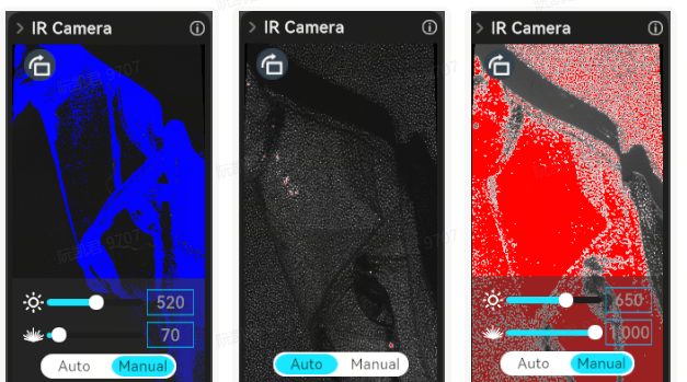
Switch to "Manual" mode to manually adjust the IR exposure for optimal point cloud quality. IR exposure defaults to automatic (for large objects, human figures, or faces). If automatic exposure isn't satisfactory, switch to manual exposure and adjust the image to normal exposure (no blue or red) for better results.
.png)
-
RGB camera preview window: The lower right window displays the color image of the RGB camera.
RGB exposure can be adjusted automatically or manually to obtain satisfactory RGB image effects.
.png)
-
Distance indicator: On the right side of the scan settings. When the distance between the scanner and the scanned object is at the "optimal distance", the point cloud acquired is optimal and the tracking stability is the best. When scanning, please pay attention to the reminders on the distance indicator bar to keep the scanner within the optimal distance range.
The distance indicator can be switched between cursor and histogram modes. Beginner users are recommended to use cursor mode, while expert users are recommended to use histogram mode.
.png)
Setting the Scanning Range supports adjusting the distance range of point cloud acquisition. Point clouds outside the range will not be acquired and displayed in the 3D point cloud rendering area.
- 3D point cloud rendering area: The main area is used to preview the current frame point cloud acquired by the scanner and the point cloud acquired historically.
In the pause phase, the point cloud can be manipulated when the cursor enters the 3D point cloud rendering area.
| Button | Operate | Remark |
|---|---|---|
| Left mouse button | Press and drag to rotate point cloud | Pause scanning |
| Press scroll wheel | Press and drag to pan the point cloud | Pause scanning |
| Scroll wheel | Scroll to zoom in/out the point cloud | Pause scanning |
Reset view: In the pause phase, after operating the point cloud, the point cloud can be restored to the state when it was paused.
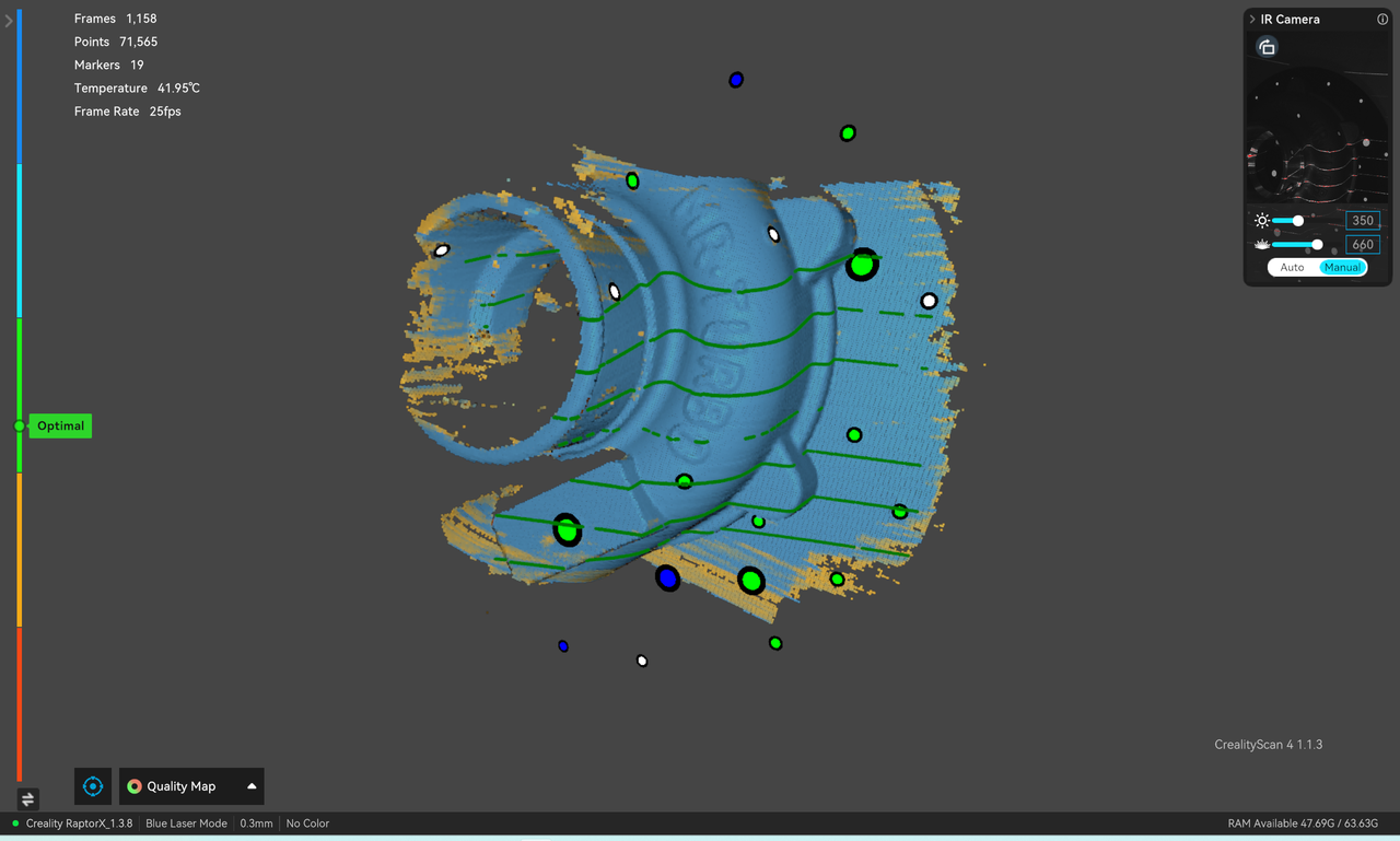
Point cloud rendering mode switching supports switching to three modes: Without Texture, Quality Map, With Texture. The default is "Quality Map". In quality map mode, it is recommended to fully scan until the point cloud of the scanned object turns green before “Complete Scan” and enter subsequent processing. The upper left corner displays the current number of frames acquired, the number of point clouds acquired in history, the current scanner device temperature, and the acquisition frame rate.
- Current status display: The upper left corner displays the number of frames currently acquired, the number of point clouds acquired historically, the current scanner device temperature, and the acquisition frame rate. The lower left corner displays the model, firmware, and scan settings, and the lower right corner displays the available memory.
¶ Blue Laser Mode
For optimal scanning quality, we recommend using blue laser mode without color mapping.
The main differences from infrared mode are as follows:
- In the depth camera preview window, click to expand the menu to adjust the laser brightness. In semi-outdoor scenes, you can manually increase the brightness to reduce sunlight interference. When adjusting, ensure the window is properly exposed (no blue or red).
- Undo/Redo is not supported.
Blue Laser Scanning Tips:
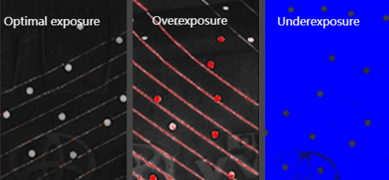
- During the preview, adjust the IR exposure and laser brightness to ensure the depth camera's markers and laser lines are properly exposed (refer to the picture below. Blue indicates underexposure, red indicates overexposure, and the best state is light white.). Aim the scanner at a feature-rich area of the object and adjust the distance between the scanner and the scanned object to the "optimal distance" according to the distance indicator bar.
- Click "Start" to start real-time scanning. During the scanning process, while maintaining a relatively fixed distance, slowly move the scanner back and forth towards the scanned part until the point cloud turns blue (Quality Map), then move it back and forth to the unscanned part to continuously ensure normal exposure and "optimal distance".
- Continue scanning according to the on-screen prompts until all point clouds turn blue.
Click "Complete" to end the scan and enter the "Fusion" process.
¶ Infrared Mode
¶ Scanning Tips
- When previewing, ensure that the depth camera preview window is in a normal exposure state (refer to the picture below. Blue indicates underexposure and red indicates overexposure, and the best state is when there is no blue or red.). Aim the scanner at the feature-rich part of the scanned object, and adjust the "optimal distance" between the scanner and the scanned object according to the distance indicator bar.
-
Click "Start" to start real-time scanning. During the scanning process, while maintaining a relatively fixed distance, carefully and slowly move the scanner towards the unscanned part of the object, and continue to ensure normal exposure and “optimal distance”.
-
Turn on the "Quality Map" mode, continue scanning according to the interface prompts until all point clouds of the scanned object turn green, indicating that all model data has been acquired and the model quality is high.
.png)
¶ Point Cloud Processing
After scanning is completed, one-click processing or manual processing is supported. The manual processing sequence is Fusion-Mesh-Color Mapping. After point cloud fusion, you can choose to edit the point cloud or use it for aligning multiple point clouds.
The main window is mainly used to display point clouds or models. The cursor enters the 3D model preview area to operate the point cloud/mesh model, as follows:
| Button | Operate |
|---|---|
| Left mouse button | Press and drag to rotate point cloud |
| Press scroll wheel | Press and drag to pan the point cloud |
| Scroll wheel | Scroll to zoom in/out the point cloud |
¶ Multi-project Panel
The left Multi-Project Panel displays a list of currently open multi-projects. During the processing of each sub-project, a maximum of three data states can be unlocked, namely Original (Point Cloud), Fused (Point Cloud), and Markers. Meshes and textures are displayed separately at the end of the project, and their display can be switched manually. Users can right-click to delete or rename.
.jpg)
There are two button options in the upper right corner of the Project Panel:
- Import the project as a sub-project of the current multi-project: Import from local device/Import from mobile device.
- Delete the current sub-project.
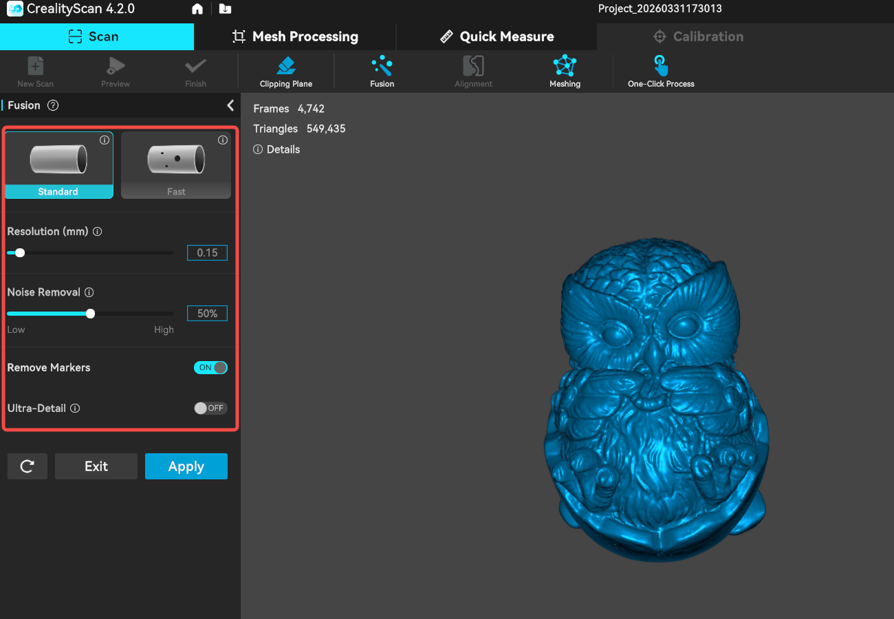
¶ Fusion
Click "Fusion" on the scan page to enter the point cloud fusion interface.
.jpg)
CrealityScan offers two pointcloud fusion methods for Blue laser scanning: Standard and Fast. The Fast mode processes data more quickly and produces meshes with more accurate edges. The mesh obtained using the Standard mode tends to be more complete.
Noise Removal: The lower the noise reduction level, the more data can be retained.
Remove Markers: This function is only displayed when using blue laser scanning or when markers are set in tracking mode. It is used to remove markers and fill the corresponding holes.
Ultra-Detail (only available for Blue laser scanning): The resolution can be set to a smaller value when enabled. (effective only when the computer memory is greater than 8G)
The CrealityScan software allows users to perform pointcloud fusion multiple times. For instance, if you are not satisfied with the current results, you can modify the parameters and re-run the pointcloud fusion step.
¶ Meshing
On the "Scan" processing interface, click "meshing" to enter the mesh construction interface.
.png)
Map the scanned 3D point cloud data to the mesh. Users can customize parameters, including setting the maximum number of faces, smoothness level, whether to fill holes, whether to remove markers, and whether to close the mesh.
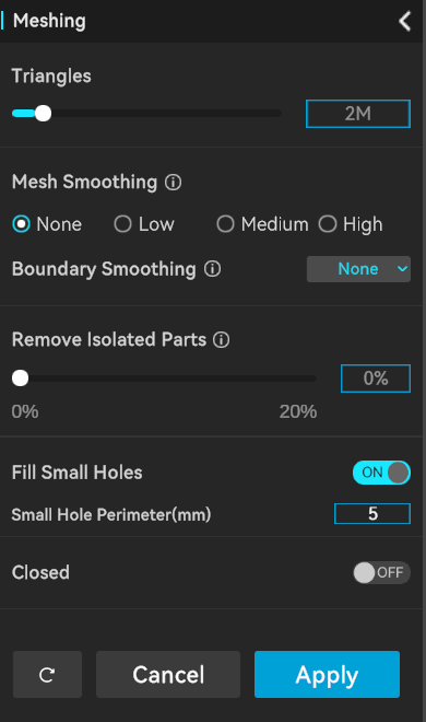
- Triangles: The higher Triangles is set, the higher the degree of detail restoration of the model.
- Mesh Smoothes: The higher the smoothness level, the smoother the mesh.
- Boundary Smoothing: Smoothes the model and the boundaries of holes.The higher the smoothness level, the smoother the mesh.
- Remove Isolated Parts: Eliminates isolated components in the model. The larger the value, the more faces will be removed.
- Fill Small Holes: The hole-filling mode will automatically fill holes in the model.
- Closed: The closing mode will automatically generate the missing surfaces of the model and create a geometrically closed 3D model. The non-closing mode will not automatically generate missing surfaces.
¶ Model editing
Creality Scan provides pointcloud editing functionality.
After scanning is complete, you can immediately use the point cloud editing feature to remove unnecessary parts, which can accelerate the data processing process.
| Icon | Function Description |
|---|---|
| Penetrate Selection: Supports selecting the mesh behind the selected area. For the raw data, selection always has a penetrate selection effect by default, so this option cannot be turned off. | |
| Lasso Select: Selects an area by dragging the mouse. | |
| Rectangle Select: Selects an area in a rectangular shape. | |
| Connected Component: Select all connected points in the clicked area. | |
| Invert Selection: Automatically selects the unselected area (opposite of the current selection). | |
| Unselect: Cancels the current selection. | |
| Delete Selection: Removes the selected part. | |
| Undo:Reverts the last deletion operation. | |
| Redo:Restores the last undone deletion operation. | |
| Cancel Edit:Exits the editing mode without saving changes. | |
| Saved Edit: Saves the editing changes and exits the editing mode. |
.png)
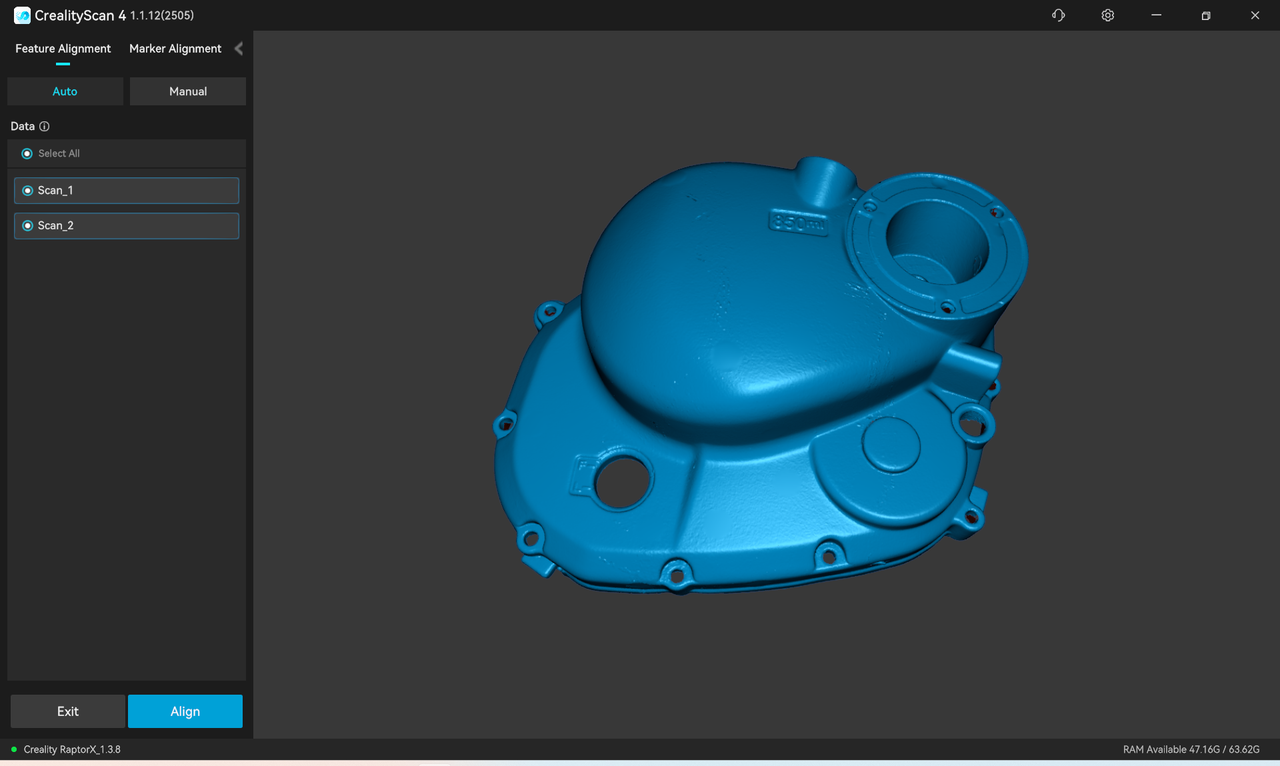
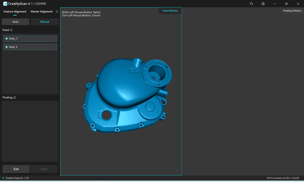
¶ Multi-project Alignment
When there are at least 2 projects that have undergone point cloud fusion in the Multi-Project Panel, click "Alignment" on the processing page to enter the stitching page.
.png)
Multi-project Alignment provide 4 modes: Feature Alignment-Auto,Feature Alignment-Manual, Marker Alignment-Auto, Marker Alignment-Manual. You can switch between modes at the top of the left-side list:
- Auto alignment (feature and marker) requires sufficient overlapping features or markers between two models.
- Manual alignment (feature and marker) requires at least three pairs of corresponding points on the fixed and floating window models.
¶ 1.Auto Feature Alignment
The left sidebar is the model list. In the auto feature alignment mode, select two target alignment sub-projects in the model list, then click "Align" and wait for the alignment to complete.
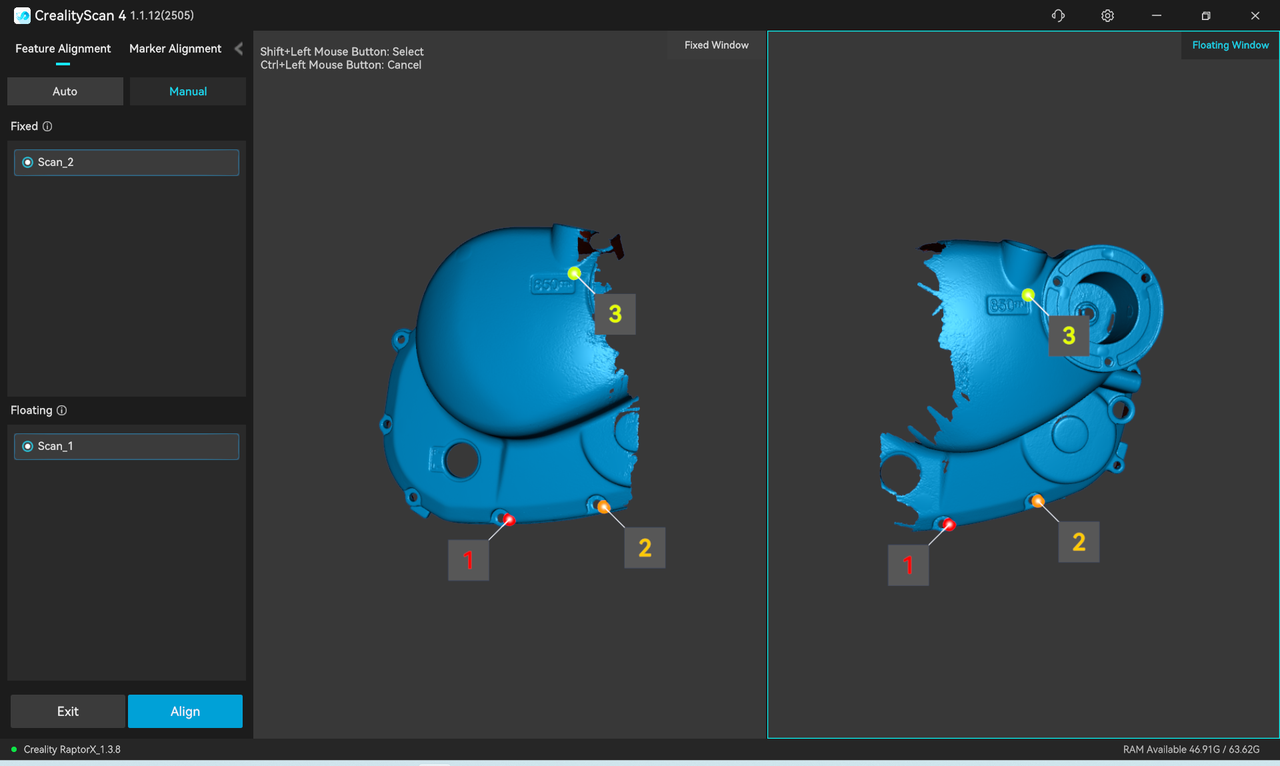
¶ 2.Manual Feature Alignment
The left sidebar displays a list of fixed and floating windows. In the manual feature alignment mode, select a sub-project to be aligned from each of the two lists on the left and display it in the corresponding fixed and floating windows. Then, select at least three pairs of matching points on the models in the fixed and floating windows.。
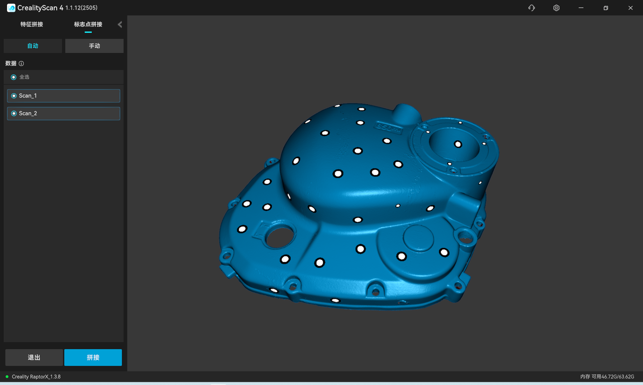
¶ 3.Auto Marker Alignment
The left sidebar is the model list. In the auto marker alignment mode, select two target alignment sub-projects in the model list, then click "Align" and wait for the alignment to complete.
¶ 4.Manual Marker Alignment
The left sidebar displays a list of fixed and floating windows. In the manual marker alignment mode, select a sub-project to be aligned from each of the two lists on the left and display it in the corresponding fixed and floating windows. Then, select at least three pairs of matching markers on the models in the fixed and floating windows.
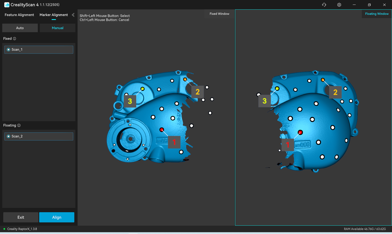
Finally, click "Align" and wait for it to complete.
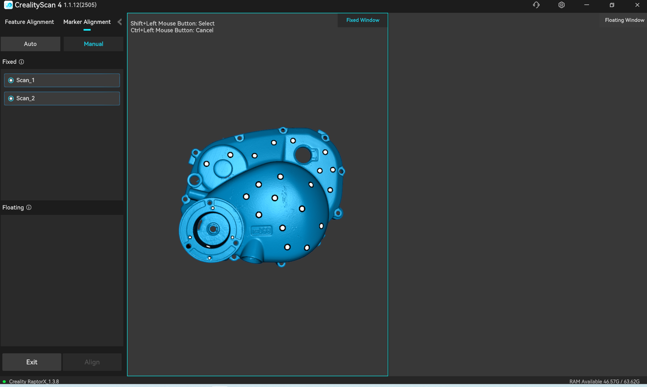
After confirming the alignment result, users can continue aligning two by two or click "Exit" to leave the alignment interface.
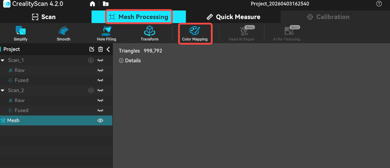
¶ Color mapping
The Raptor scanner is equipped with a high-definition RGB camera, allowing for the capture of true-color textures for 3D models.
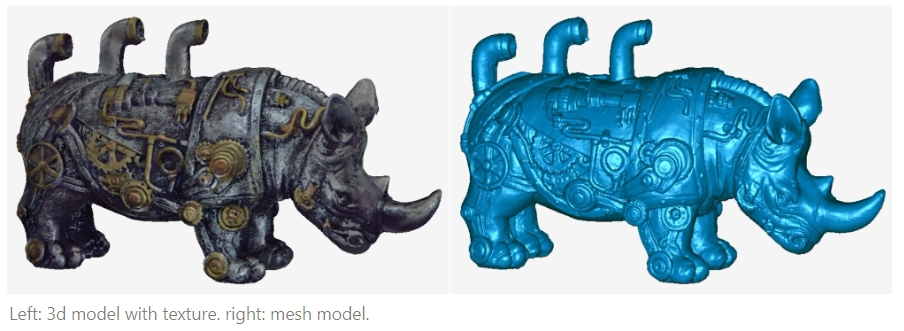
After meshing is complete, if the color mapping function is enabled in the scanning settings, you can click Mesh Processing -> Color Mapping to apply the texture.
¶ Export the completed 3D model
.png)
- Optimized point clouds support export in .asc, .ply, .stl, and .obj formats.
- Meshes support export in .asc, .ply, .stl, and .obj formats.
- When exporting texture images, only supported.ply ,.obj packages (including .obj, .mth, and .png files)
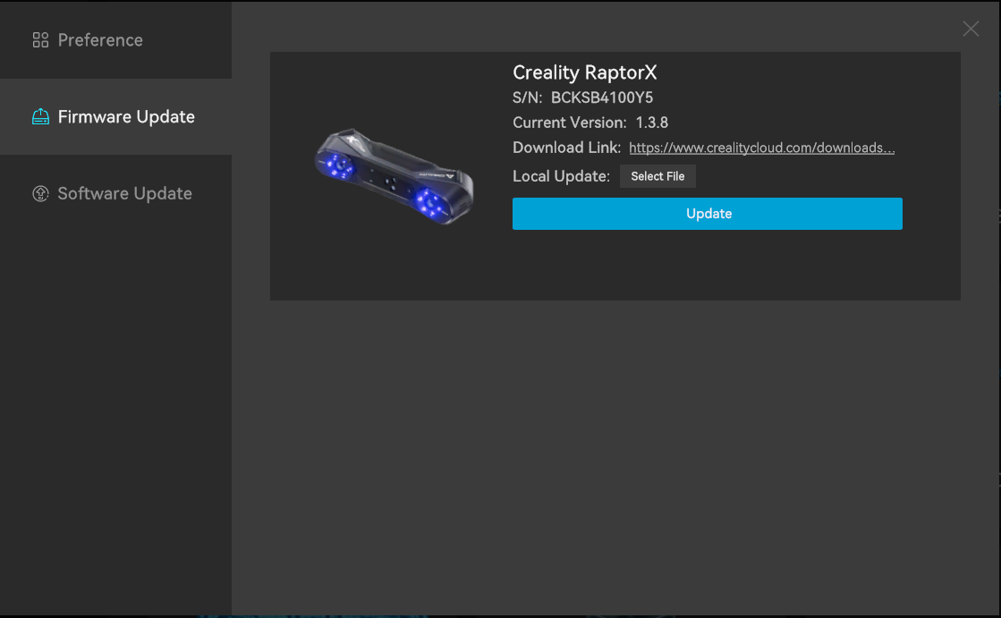
¶ Firmware Upgrade
Firmware upgrade is divided into automatic detection upgrade and manual firmware upgrade.
- After the scanner is successfully connected, if the software has an internet connection, it will automatically detect whether the scanner's firmware version needs an update. You can proceed with the update after confirming it manually.
- To update the firmware manually, navigate to Settings > Firmware Update in the top right sidebar. Download the corresponding latest firmware from the provided download link, click "Select File", then click "Update Now" and wait for the process to complete.