¶ Installation
¶ Software
https://www.crealitycloud.com/software-firmware/software/creality-scan
¶ Firmware
https://www.crealitycloud.com/software-firmware/other/type-26
(* Normally, you don't need to download the firmware manually. You can click Install in the prompt of the latest version of the software. Only if the installation fails, you need to try to install the firmware manually.)
¶ Windows 10/11 (64-bit)
Recommended configuration: CPU i7-Gen8 and above, Nvidia graphics card, 16GB RAM or above
Minimum configuration: CPU i5-Gen8 and above, 8GB RAM or above.
Software version: Creality Scan ≥ v3.1.22
¶ macOS
Recommended configuration: CPU Apple M1/M2/M3 series processor, 16G RAM or above
System version macOS 11.7.7 and above (Big Sur/Monterey/Ventura)
Minimum configuration: CPU i5-Gen8 and above, 8GB RAM or higher.
System version macOS 10.15.7 and above (Catalina/Big Sur/Monterey/Ventura)
Software version: Creality Scan ≥ v3.1.22
¶ Otter-series' Recommended Smart Phone Model
| Brand | Model | ||||
|---|---|---|---|---|---|
| iPhone | iPhone 16series | iPhone 15series | iPhone 14 series | iPhone 13 series | iPhone 12 series |
| Samsung | S24 series | S23 series | S22 series | S21 series | Note20 series |
| Z fold 3~6 | Z flip 4~6 | ||||
| Pixel 9 series | Pixel 8 series | Pixel 7 series | Pixel Fold | ||
| XIAOMI | 14 series | 13/13T series | 12/12T series | Redmi K70 series | |
| Motorola | Razr+ 2024 | Edge 50 Ultra | X50 Ultra | Edge 40 Pro | X40 |
| Edge 30 Ultra | X30 Pro | ||||
| OnePlus | 12 | 11 | 11 R | 10 Pro | 9 R |
| 9 | Ace 3 series | Ace 2 series | |||
| OPPO | Find X7 series | Find X6 /X6 Pro | Find X5 Pro | Find N3 series | Find N2 series |
| Nubia | RedMagic 8 pro/pro+ | RedMagic 9 pro/pro+ | RedMagic 9s pro/pro+ | ||
| Vivo | X200 series | X100/X110s series | X90 Pro/Pro+ | S19 Pro | |
| Honor | Magic 4/5/6 | Magic Vs3/Vs2/Vs | Magic 4/5/6 Pro | Honor 100/200 Pro |
¶ Home Page
.png)
Check whether the scanner is connected successfully in the upper left infobox of the homepage. It is recommended to use USB3.0 to connect the scanner.
① The left column shows the basic information of the device at the top, and supports entering the calibration page. '"Home", "User Guide", and "Discovery" are displayed below.
② The main area on the right side lists the recently opened projects. Click the corresponding picture to open the corresponding project.
.png)
③ Click “New Project” at the top to start the scan. Click “Open”, there are two options: click "Open Project or Model" to import projects from the local folder (.obp format) or view the model (.stl, .obj, .ply format); click “Import from Phone” to import projects from the "Creality Scan" APP through the LAN, and be sure to keep the mobile phone and computer in the same LAN.
④ The settings button on the top right supports switching languages and changing other settings.
.png)
⑤ If there are too many projects, users can search for the corresponding project through the search box.
¶ Quick Calibration
Reference Video:
https://www.youtube.com/watch?v=9L9K1wuEInc
After the device is connected, enter through the calibration button in the upper left infobox of the homepage.
.png)
When using it for the first time, be sure to aim the scanner at the back of the calibration board that comes with the package to scan the QR code.
.png)
After entering the acquisition process, be sure to aim the scanner at the front of the calibration board and move the scanner according to the guidance. When placing the calibration board on the desktop, pay attention to the arrow pointing upward.
.png)
The left side is the process guidance area, the "yellow scanner" displays the pose and angle requirements for the current acquisition. The "black scanner" represents the actual position of the scanner. Pay attention to matching the direction of the scanner and the calibration board as shown in the illustration.
The bottom of the guidance area displays the calibration board number and scanner temperature. Please make sure to perform calibration within the appropriate temperature range.
The calibration board area on the right side is mainly used to 3D guide the posture and angle of the scanner in real time. Slowly moves the scanner to the position indicated by the "yellow scanner". The "yellow scanner" will jump to the next height if qualified and maintain the same position unchanged if unqualified.
.png)
Upon completing all height acquisition of one angle, it will automatically enter the next stage of angle acquisition. Please move the scanner according to the guidance and repeat the entire process to collect all angles.
There is a step indicator bar on the far right. Upon completing all the steps, it will automatically enter the calibration process. Please wait patiently for the calibration results. After the calibration is successful, please turn on scanning for a high-quality scanning experience.
¶ Scanning Configuration
Click "New Project" , and in the pop-up window, users can set the project name and project save path. It is recommended to use the name of the scanned object as the project name to increase recognition.
.jpg)
In the "Scan Settings" area of the left sidebar, select the appropriate configuration based on the requirements of the scanning object and environment, referring to relevant video tutorials.
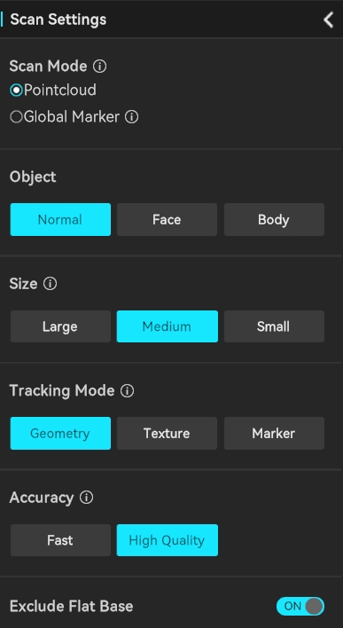
¶ Scan mode selection
In the Creality Scan software, multiple scanning modes are provided. It is important to choose the appropriate scanning mode for different types of targets.
How to choose Feature type?
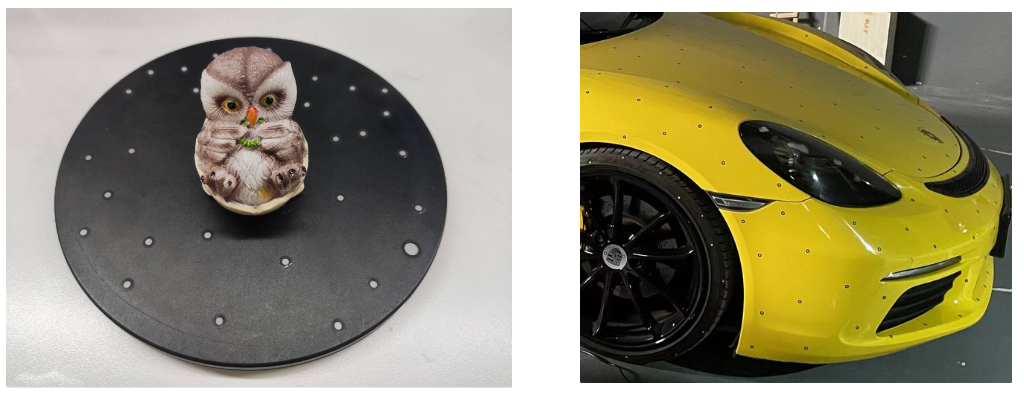
(1) Geometry: For objects with rich geometric features, it is recommended to use the Geometry Mode for scanning.
(2) Texture: For small objects with limited geometric features, it is suggested to apply the Texture Mode after placing marker points. For very small objects, the marker points can be placed on the table. For objects with rich texture but limited geometric features, the Texture Mode can be directly used for scanning.
(3) Marker: For large objects where reliable accuracy is desired, it is recommended to use the Marker Mode for scanning. This mode requires Non-reflective circular marker points to be attached to the surface of the object. For large objects, marker points with an inner diameter of 6mm should be used, while for small objects, marker points with an inner diameter of 3mm can be used.
How to determine if an object has rich geometric features?
Objects that have regular geometric shapes, or objects with large flat surfaces, such as cubes, cylinders, cylindrical mugs, square-shaped boxes, or truck cargo compartments often lack sufficient distinctive geometric features and do not have rich geometric features.
On the other hand, objects like portrait sculptures, shoes, or doll models have rich geometric features.
¶ Accuracy Setting
If you want to obtain better details, do not hesitate to choose “High-Quality”. If your computer has a dedicated graphics card (i.e. GPU), the High-Quality mode will provide smoother performance.
For large objects or lower computer specifications, you can choose "Fast Mode“ for scanning.
¶ Exclude Flat Base
Click  to enable or disable it, and the function will take effect in real time. When enabled, it can automatically remove planar background detected during scanning
Note:
- It is recommended to enable this function when scanning objects on the table that are small but do not require the assistance of markers.
- When the object to be scanned is extremely small and difficult to scan (e.g., only a few centimeters in size), it is recommended to use the "Marker" mode to scan after pasting markers on the desktop. Do not choose to “exclude flat base” at this time.
¶ Real-time Scanning
Click "Preview" to enter the main scanning interface for preview and scanning.
.png)
¶ 1.Start scanning/Pause scanning/ Restart scanning
Click Preview, point the scanner at the object you want to scan, and click "Start" to begin scanning. Click "Pause" to stop scanning.
When resuming after a pause, ensure that the scanner is aimed at the scanned and feature-rich area to quickly return to the state of tracking scanning.
Click "Fnish" to complete the scanning and will enter the processing page.
¶ 2. Clear/Undo/Redo/Reset
During the preview stage, if you need to adjust the scan settings, you can click "Reset" to reset the scan settings and start a new preview.
After starting the scan, click "Delete" to delete the currently scanned data and return to the preview state.
¶ 3. Depth Camera Preview Window:
Depth Camera Preview Window:
- The default exposure mode is auto exposure (auto exposure can be used for shooting large objects, human bodies, or faces).
- If the exposure effect is poor in auto mode, you can click "Manual" to manually adjust the infrared exposure to obtain the best point cloud effect.
- It is recommended to adjust the image to normal exposure (without blue or red) for better results.
 Click the rotation icon in the upper left corner of the window to perform a "Rotate right 90°" .
RGB Camera Preview Window:。
The RGB camera window displays the color image of the RGB camera.Click "Manual" to manually adjust RGB exposure and achieve a satisfactory RGB image effect.
Click the rotation icon in the upper left corner of the window to perform a "Rotate right 90°".
 If the environment is dark, click the light bulb icon under the rotate icon to enable the supplemental light for better color mapping.
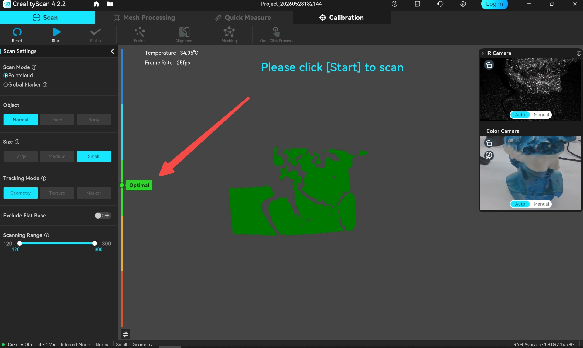
¶ 4. Distance Indicator Bar
Located on the left side of the main scanning interface, when the distance between the scanner and the object being scanned is at the "optimal" distance, the quality of the collected point cloud is optimal, and tracking stability is also optimal.
During scanning, please pay attention to the prompts on the distance indicator bar and promptly keep the scanner within the "optimal" distance range.
 Supports switching the distance indicator bar to cursor mode and histogram mode. It is recommended that beginners use cursor mode, while professional users use histogram mode.
Set the scanning range in the left sidebar, adjust the distance range for point cloud collection, and point clouds outside this range will not be collected or displayed in the 3D point cloud rendering area.
¶ 5. 3D Point Cloud Rendering Area
The main area is used to preview the current frame point cloud collected by the scanner and the point clouds collected historically.
.png)
During the pause phase, when the cursor enters the 3D point cloud rendering area, the point cloud can be operated on.
| Button | Operation | Remarks |
|---|---|---|
| Left mouse button | Hold and drag to pan the point cloud | Pause scanning |
| Middle button pressed | Hold and drag to rotate the rendering view | Pause scanning |
| Middle mouse button scroll | Scroll to zoom in/out the point cloud | Pause scanning |
.png) Reset: During the pause phase, after operating on the point cloud, the point cloud can be restored to its state at the time of the pause.
Reset: During the pause phase, after operating on the point cloud, the point cloud can be restored to its state at the time of the pause.
![]() Point cloud rendering mode switching: supporting switching to Without Texture, Quality Map, and With Texture. The default is "Quality Map". In the chromatogram mode, it is recommended to fully scan until the point cloud of the scanned object turns green before clicking "complete scan" to proceed to subsequent processing.
Point cloud rendering mode switching: supporting switching to Without Texture, Quality Map, and With Texture. The default is "Quality Map". In the chromatogram mode, it is recommended to fully scan until the point cloud of the scanned object turns green before clicking "complete scan" to proceed to subsequent processing.
¶ 6.Turn off "Full Screen Scanning"
By default, full-screen scanning display is enabled. If you need to see the IR camera preview window and RGB camera preview window during the scanning process, you can turn off "Full Screen Scanning" in "Settings" .
.png)
¶ 7.The current status shows (frames number, point cloud number, frame rates, temperature, available memory)
The number of currently collected frames, historically collected point clouds , the current scanner device temperature, and the collection frame rate are displayed in the upper left corner.
On the left side of the bottom status bar, the device connection status and scanning settings are displayed, while on the right side, the available memory is shown.
¶ Scan Suggestions
- When previewing, ensure that the depth camera preview window is in a normal exposure state (refer to the picture below, if the camera preview shows blue, it indicates underexposure, while red indicate overexposure).
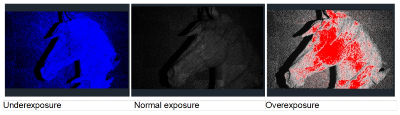
-
Click "Start" to start real-time scanning. During the scanning process, while maintaining a relatively fixed distance, carefully and slowly move the scanner towards the unscanned part of the object, and continue to ensure normal exposure and “optimal distance”.
-
Turn on the "Quality Map" mode, continue scanning according to the interface prompts until all point clouds of the scanned object turn green, click "Complete" to end the scan and enter the processing page.
¶ How to scan the bottom of an object?
When you need to scan the bottom of an object, you can place the object on a tabletop and scan the visible parts first. Then, create a new project and position the object on its side or upside-down for another scan. Use the Alignment function to merge these two sets of pointclouds together(Refer to the function guidance below), creating a complete 3D model of the object. During both scans, make sure that there are sufficient overlapping areas being captured.
After completing the first scan and performing pointcloud fusion, you can start a new scan by selecting "New Project." On the page for Alignment, you can automatically or manually merge the fused point clouds. Below is an example of manual alignment.
¶ Processing Page
After scanning is completed, it supports one-click process or manual processing. The sequence of manual processing is fusion - meshing - color mapping. Before fusion, you can edit the point cloud (delete redundant point clouds). After fusion, you can choose to continue editing the point cloud or use it for alignment (only available when there are two or more fused point clouds in the project panel).
¶ Point Cloud Fusion
Optimize the point cloud to obtain a better 3D point cloud model. There are two ways to achieve this function. Automatic mode ("one-click process" under "Scan") will use default parameters for fusion; Manual mode allows manual setting of resolution, noise removal, and whether to remove markers.
The smaller the resolution, the better the details, but it requires more memory and processing time.
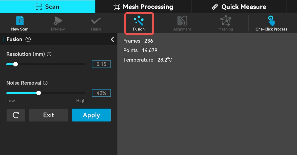
Noise Removal: The lower the noise reduction level, the more data can be retained.
Remove Markers: This function is only displayed when are set in markers tracking mode. It is used to remove markers and fill the corresponding holes. Removing markers will optimize the mesh for the identified marker positions.
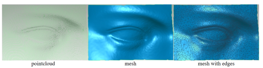
¶ Meshing
The meshing operation converts pointcloud data into a triangular mesh model.
During the meshing process, you can manually configure the number of the triangles, adjust the mesh smoothness, set the percentage for removing isolated parts, and choose whether to remove spikes, fill holes, and make the model watertight.
The more triangles in the mesh, the finer the model, but it also takes longer to generate the mesh.
.png)
- Triangles: The higher Triangles is set, the higher the degree of detail restoration of the model.
- Mesh Smoothing: The higher the smoothness level, the smoother the mesh.
- Boundary Smoothing: Smoothes the model and the boundaries of holes.The higher the smoothness level, the smoother the mesh.
- Remove Isolated Parts: Eliminates isolated components in the model. The larger the value, the more faces will be removed.
- Fill Small Holes: The hole-filling mode will automatically fill holes in the model.
- Watertight: The closing mode will automatically generate the missing surfaces of the model and create a geometrically closed 3D model. The non-closing mode will not automatically generate missing surfaces.
¶ Point Cloud/Mesh Editing
The main window is mainly used to display point clouds or models. When the cursor enters the 3D model preview area, you can operate point clouds/mesh models, as follows
| Button | Operation |
|---|---|
| Right mouse button | Click to select point cloud |
| Left mouse button | Hold and drag to pan the point cloud |
| Middle button pressed | Hold and drag to rotate the point cloud |
| Middle mouse button scroll | Scroll to zoom in/out the point cloud |
After the scan is completed, the, original point cloud and fused point cloud can be edited and processed. The editing toolbar is located on the right side of the main area.
| Icon | Function Description |
|---|---|
| Penetrate Selection: Supports selecting the mesh behind the selected area. For the raw data, selection always has a penetrate selection effect by default, so this option cannot be turned off. |
|
| Lasso Select: Selects an area by dragging the mouse. | |
| Rectangle Select: Selects an area in a rectangular shape. | |
| Connected Component: Select all connected points in the clicked area. | |
| Invert Selection: Automatically selects the unselected area (opposite of the current selection). | |
| Unselect: Cancels the current selection. | |
| Delete Selection: Removes the selected part. | |
| Undo:Reverts the last deletion operation. | |
| Redo:Restores the last undone deletion operation. | |
| Cancel Edit:Exits the editing mode without saving changes. | |
| Saved Edit: Saves the editing changes and exits the editing mode. |
.png)
Similarly, the meshed model can also be edited and processed (click the "Edit" button in the upper toolbar to perform "Mesh Simplification", "Mesh Smoothing", or "Hole Filling" operations.)
.png)
¶ Multi-project Alignment
Each scan can capture only a portion of the object, and then you can use the Multi-Project alignment feature to combine them into a complete model. This is extremely helpful for scanning larger objects.
After completing the first scan and performing pointcloud fusion, you can start a new scan by selecting "New Project." On the page for Multi-Project alignment, you can automatically or manually align the fused point clouds.

When there are at least two projects in the multi-project panel, click " Alignment " in the toolbar at the top of the "Scan" page to enter the Alignment page.
.png)
There are two types of align methods: "feature alignment" and "marker alignment", and users can switch the alignment method in the upper part of the left sidebar .
¶ 1. Feature alignment
Feature alignment provides both automatic and manual modes.
① Automatic alignment requires a sufficiently large common feature area between models.
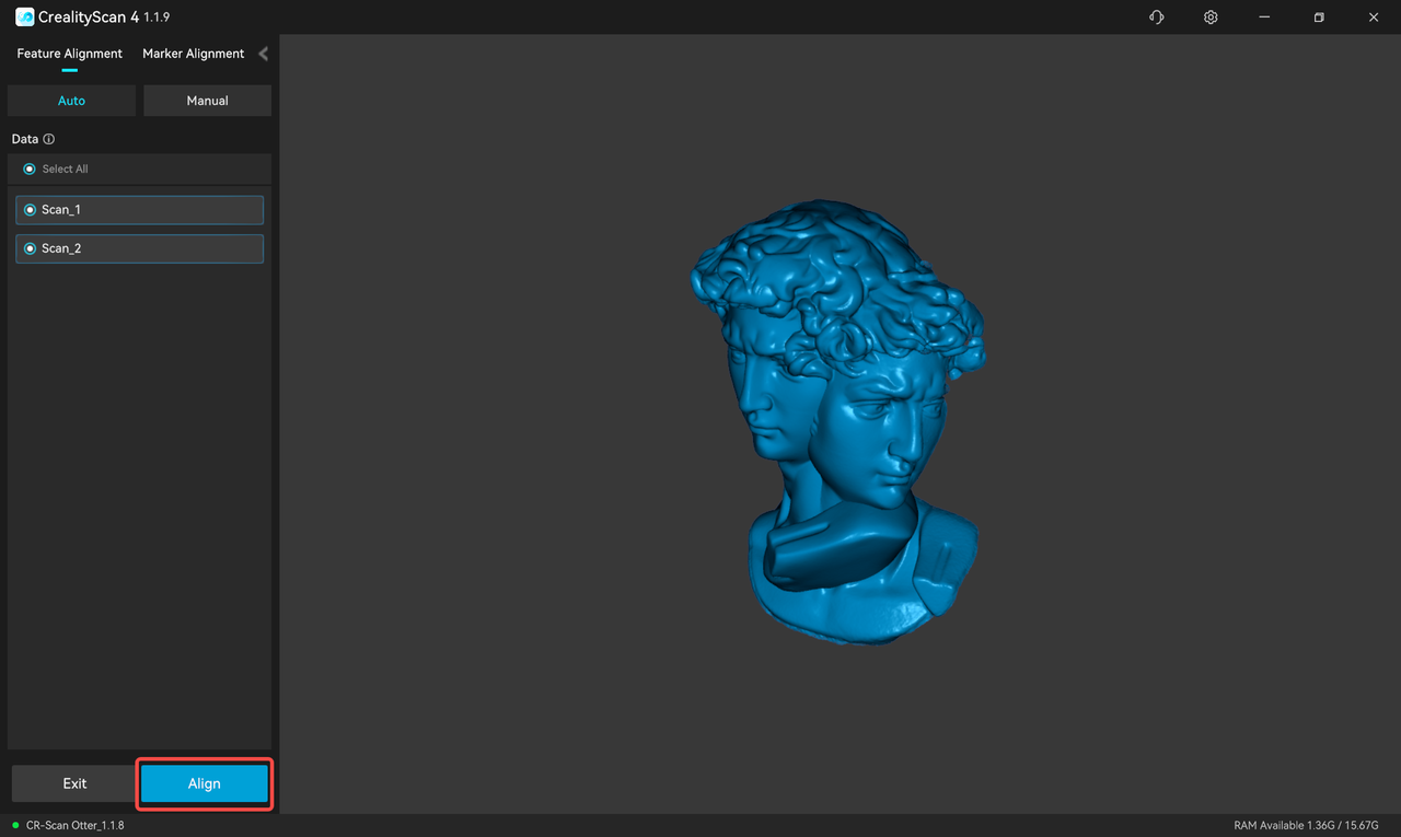
It is generally more recommanded to use Manual alignment.
On the left is the model list. In automatic Alignment mode, select two sub-projects to be spliced in the model list, then click "preview" to start alignment. After Alignment is completed, click "apply" to complete the alignment.
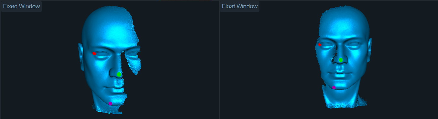
② Manual alignment
Manual alignment requires at least three pairs of corresponding points on the models of the fixed window and the floating window.
After confirming the Alignment result, click "apply" to save the change. User can continue to align one by one, or click "exit" to leave the Alignment page.
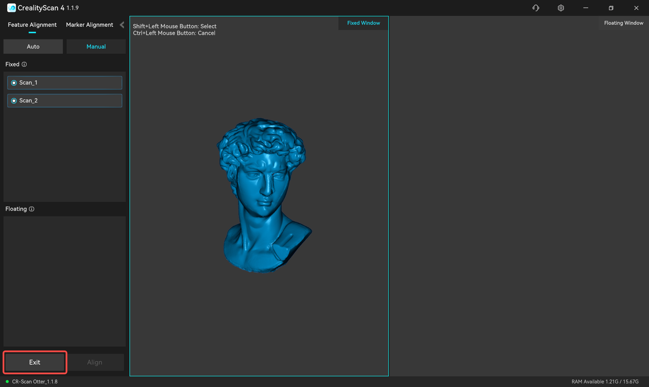
¶ 2. Marker Alignment
If you use "Marker" scanning mode, "Marker Alignment" is also available.
Marker alignment provides Auto and Manual modes.
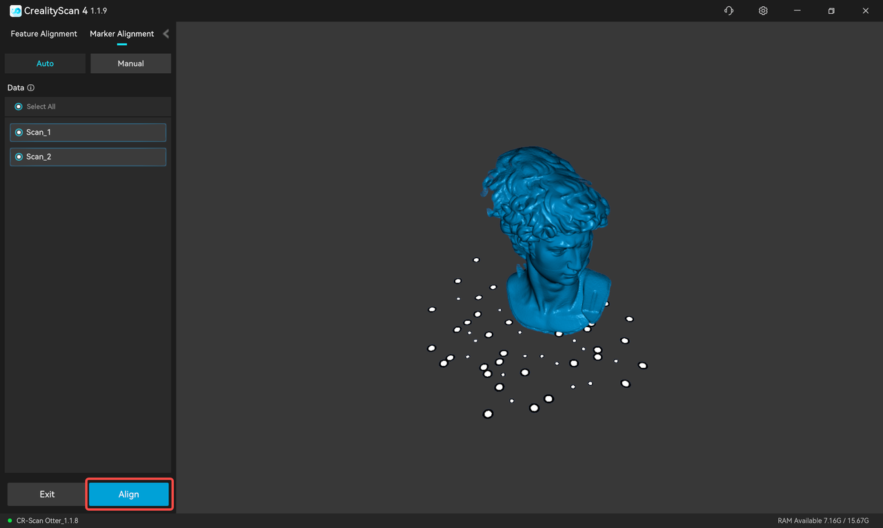
① Auto alignment requires enough overlapping marker areas between models.
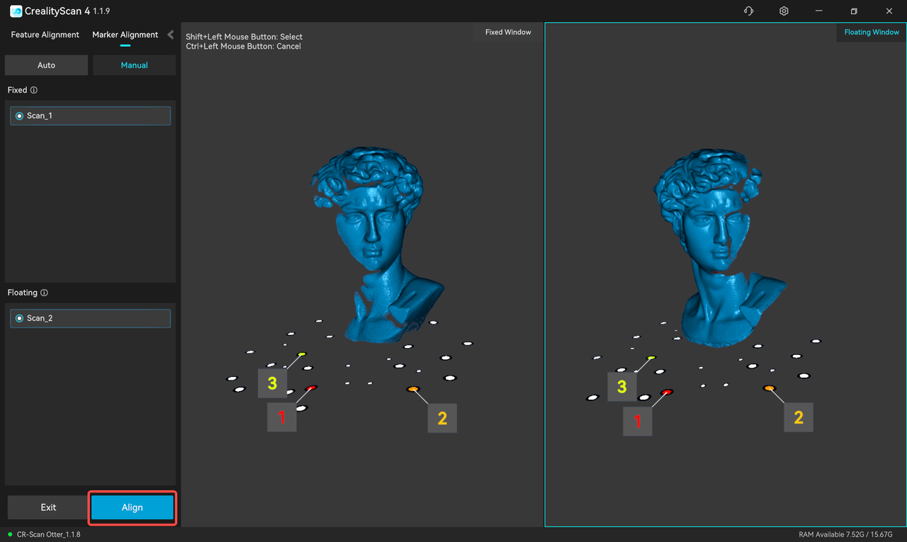
② Manual alignment requires at least three corresponding markers on each model.
Auto alignment
On the left is the model list. In auto alignment mode, select the two target subprojects in the model list, and then click "preview" to start aligning. After the alignment is completed, click “apply” to complete the alignment.
In the main area, the fixed window is on the left and the floating window is on the right. In manual alignment mode, select a subproject in the two lists on the left and display it in the corresponding fixed window and floating window, and then select at least three pairs of markers on the model in the fixed window and floating window. Finally click “preview”.
After confirming the alignment effect in the window, click “apply” to complete the alignment.
¶ Color Mapping
Match image pixels on the mesh model to improve texture and color resolution.
.jpg)
The completed effect :
.jpg)
¶ The multi-project panel
.jpg)
¶ 1. Data states display
The multi-project panel on the left shows the currently open projects/scans. Each sub-project unlocks up to four data states with the processing stage, namely raw, fused, mesh, and texture. Users can right-click to delete the corresponding data or rename the project.
¶ 2.Continue scanning
 Click to continue scanning.
¶ 3. Create New Scan/Import historical projects
.jpg) Click "New Scan"to create a new scan as a subproject of the current multi-project.
Click "New Scan"to create a new scan as a subproject of the current multi-project.
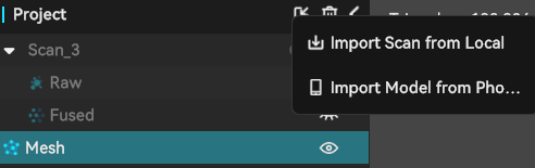
Click the first icon to the right of "Project". This feature supports:
Import Scan from Local as sub-projects of the current multi-project.
Import Model from phone as a sub-project of the current multi-project.
In the upper function bar, manual processing is recommended. The processing order is fusion - meshing - color mapping . "Point cloud fusion" is under "Scan", and "meshing" and "Color mapping" are under "Process".
¶ Export/Share 3D model
 Click the upper right corner icon of the software to Export completed 3D models. Fusion supports exporting in .asc and.ply formats. Mesh supports exporting in .stl,.ply, and.obj formats. Texture supports exporting in .ply and.obj formats.
 Click the upper right corner icon of the software to share the processed 3D model to the third party software, like Creality slicing software for direct printing.
¶ Firmware Upgrade
Firmware upgrade is divided into automatic detection and upgrade and manual firmware upgrade.
- After the scanner is successfully connected, if the software has an internet connection, it will automatically detect whether the scanner's firmware version needs an update. You can proceed with the update after confirming it manually.
- To update the firmware manually, navigate to Settings > Firmware Update in the top right sidebar. Download the corresponding latest firmware from the provided download link, click "Select File", then click "Update Now" and wait for the process to complete.
.png)