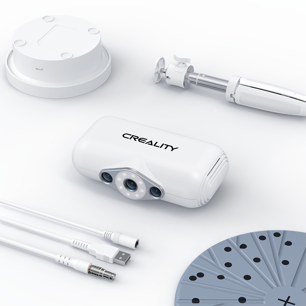
¶ Download the Software
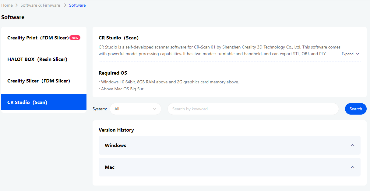
https://www.crealitycloud.com/software-firmware/software?type=11
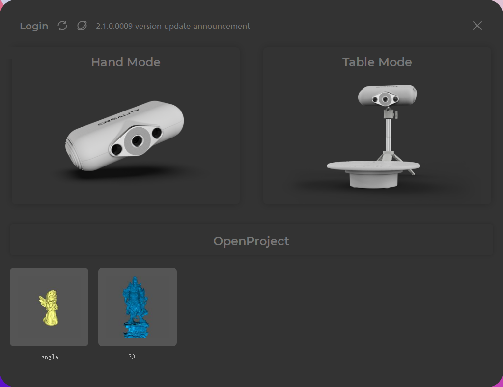
¶ Launch the Software
¶ The interface of the launching process
¶ The main interface of the software
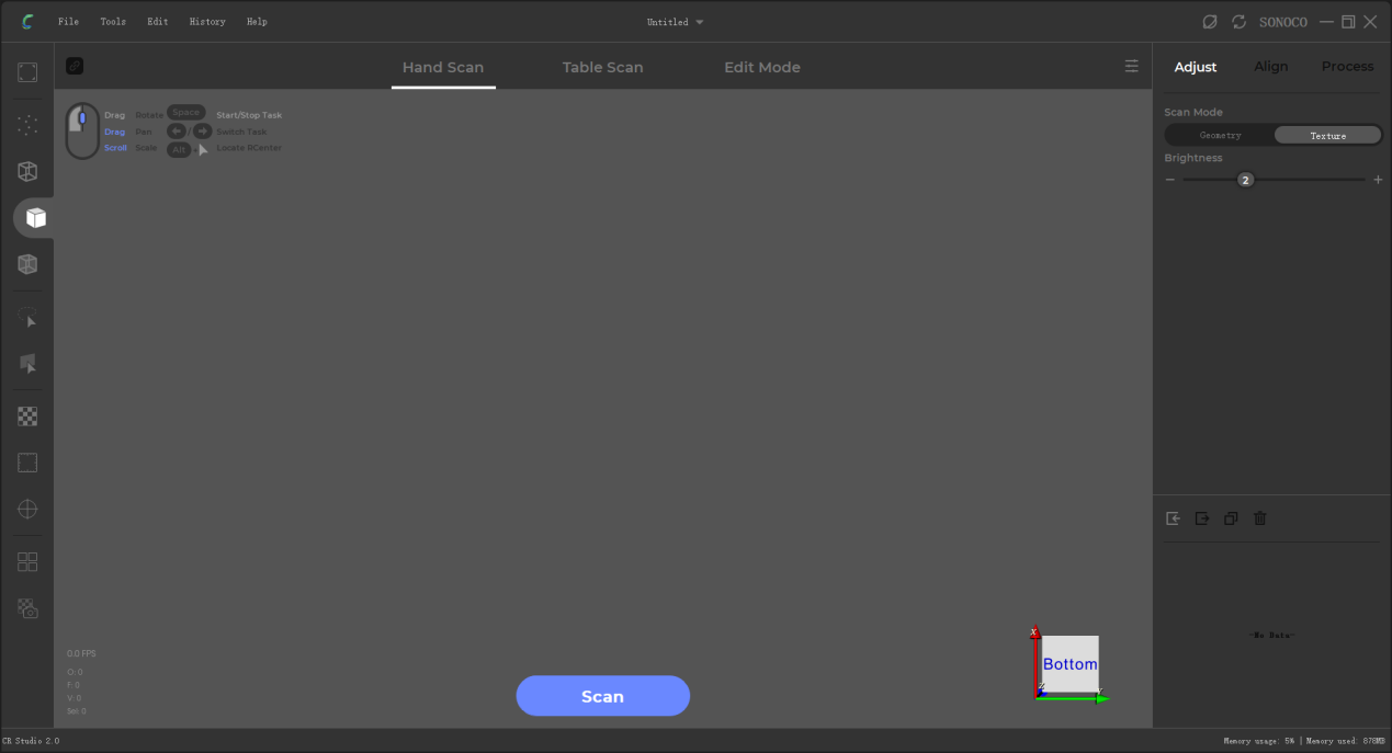
¶ Main shortcuts
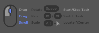
¶ Import the Calib File
¶ Click “File” in the menu-find “Import Calib”
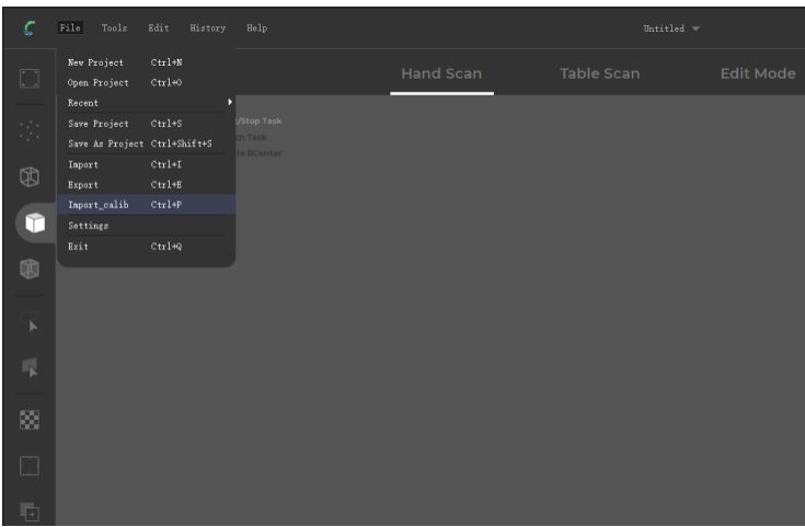
¶ Windows
Choose “Network Download”-click “Import”
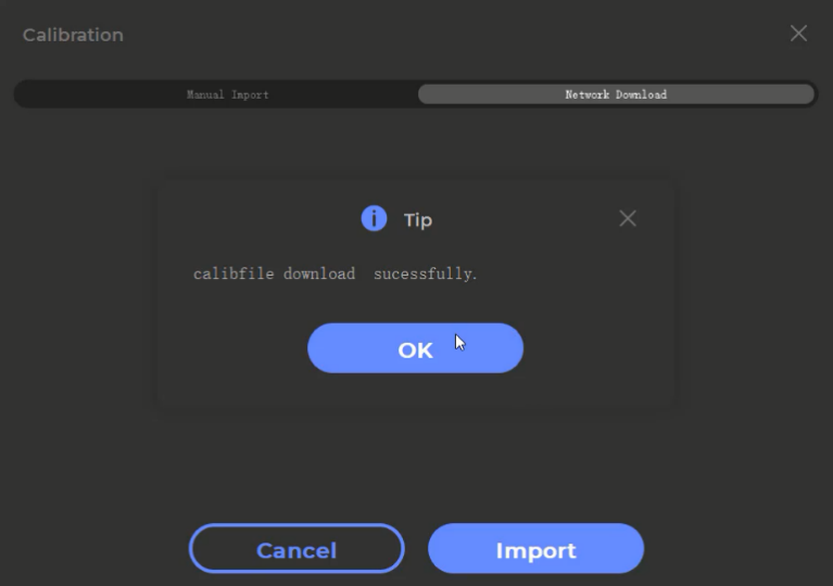
¶ Mac OS
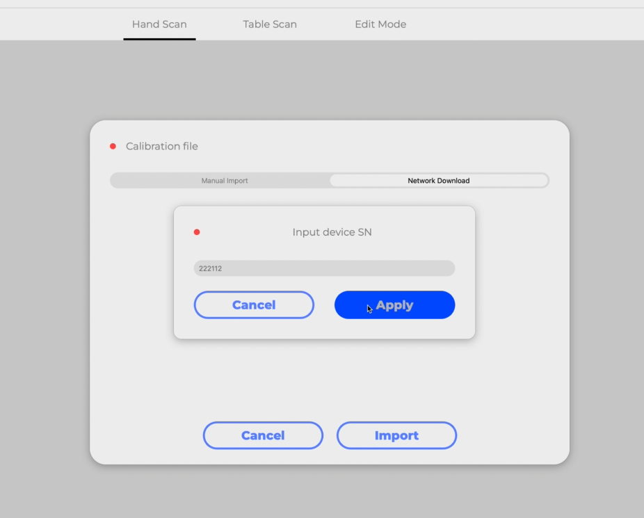
Choose “Network Download”-input the SN of the device-click “Apply” and “Import”
¶ Start the Scanning
¶ In the turntable mode
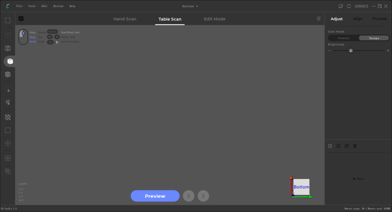
¶ Step 1: preview
Adjust the scanning angle and the distance between the turntable and the scanner to see the object in the center of the 3D view.
For CR-Scan 01, the distance should be kept within 600-800mm.
For CR-Scan Lizard, the distance should be kept within 300-400mm.
Attention: the tripod should be extended to the highest level.
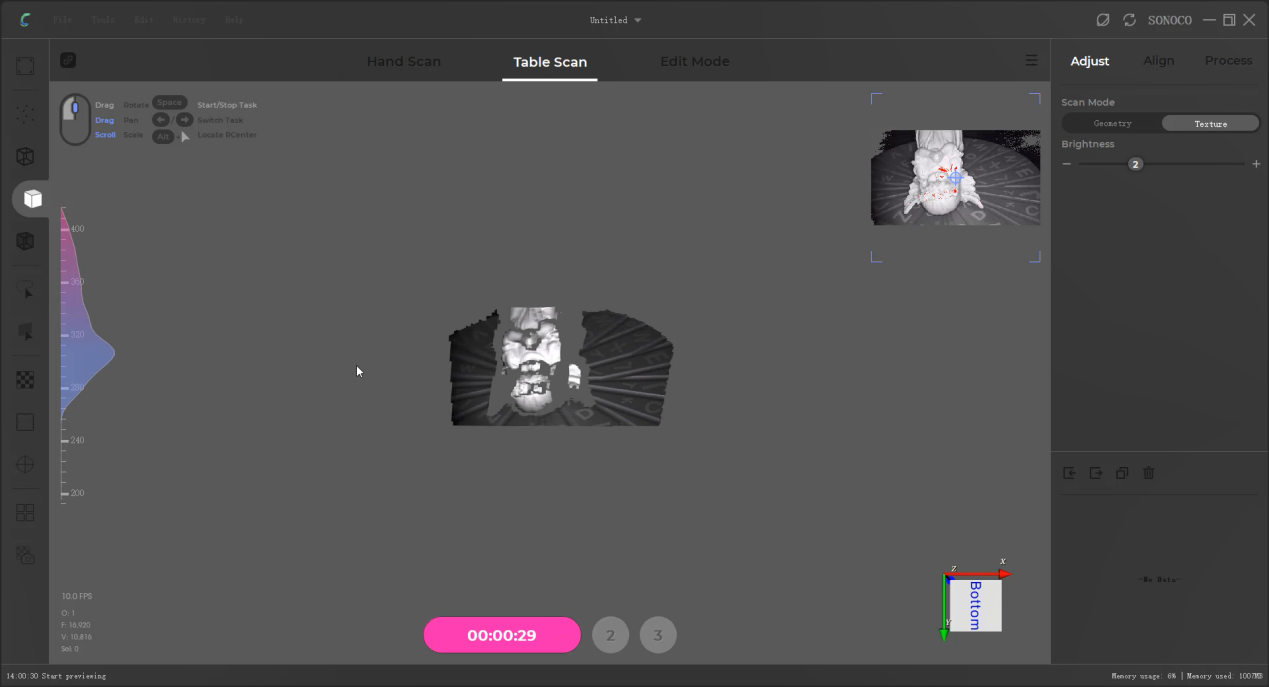
The ruler on the left side shows the scanning distance you keep. And the waveform represents whether the distance is appropriate or not.
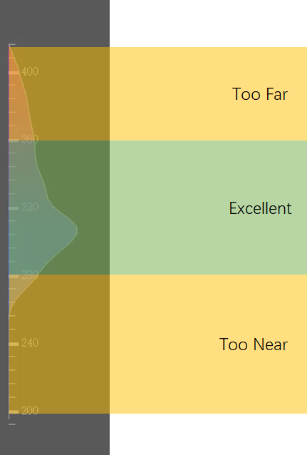
360mm-400mm: too far
280mm-360mm: excellent
200mm-280mm: too near
¶ Choose the scan mode between geometry and texture.
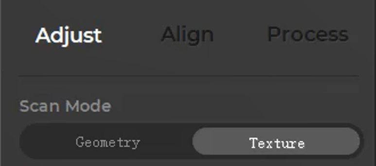
In the geometry mode
it’s suitable to scan objects with rich geometric features.
In the textural mode
it’s suitable to scan objects with vivid textures.

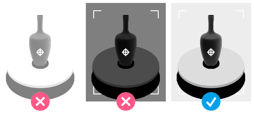
Pull the brightness adjustment slider to make the brightness appropriate.

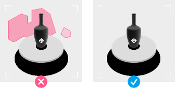
Keep the area around the turntable free of debris.
¶ Step 2: initialization
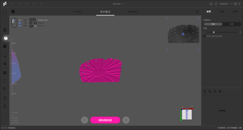
Move the object away and scan the turntable only. The initialization is successful when the turntable becomes red.
(This process takes only 1-2 seconds in most cases)
¶ Step 3: scan
Make sure the object in the center of the turntable, and click “scan” to start the automatic scanning.
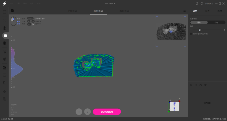
When the scanning ends, the turntable will become red automatically.
¶ Step 4: append
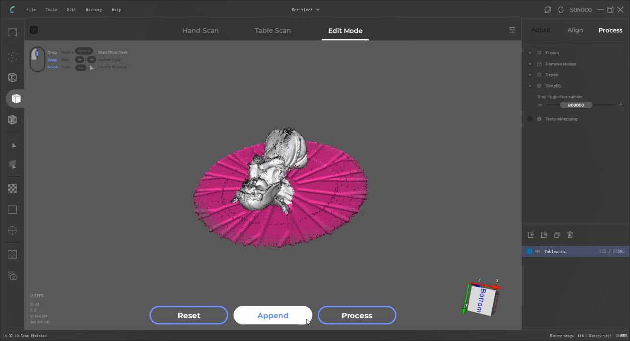
In order to get a complete scanning result, you can scan different postures. Change the posture of the object on the turntable, and click “append” and “scan” one at a time, then the automatic scan of the second posture will begin.
¶ Step 5: align
Now you can align the scanning results of different postures. First thing to do is make the models visible by picking up the scanning data, and click “align” to start automatic alignment.
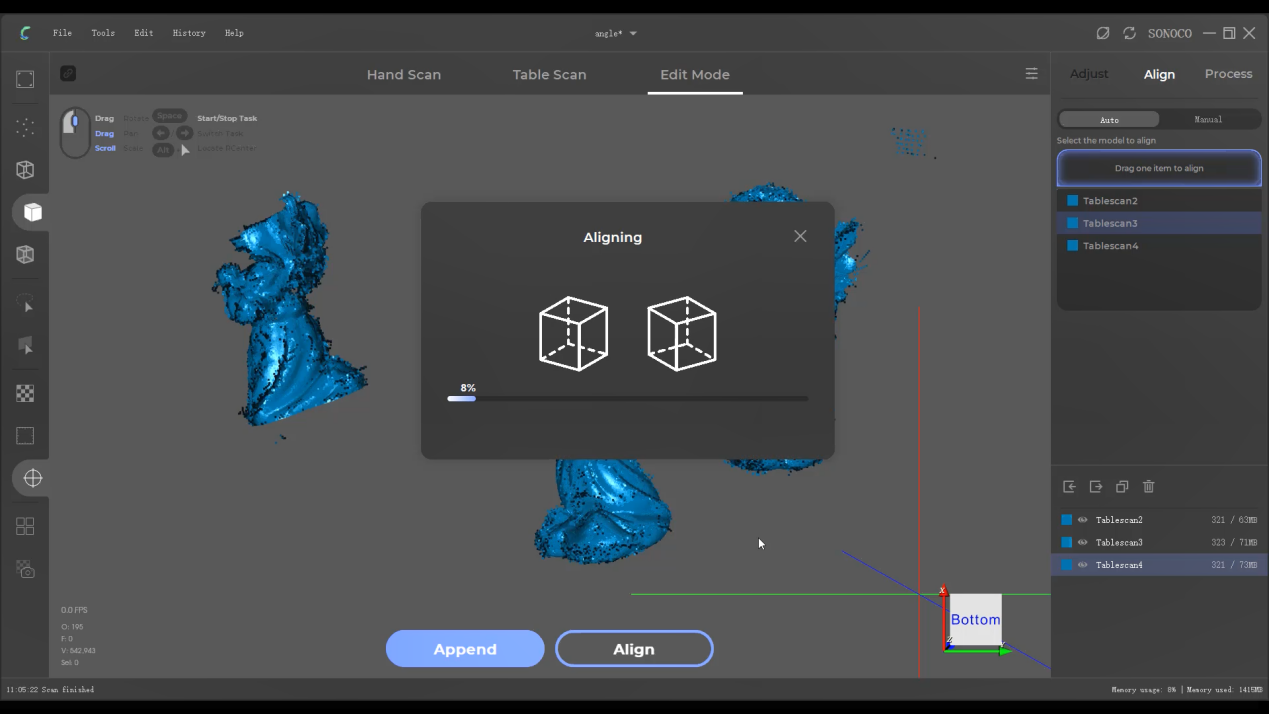
After finishing that, check whether the alignment is successful or not. If you’re not satisfied with the result, click “manual” and start manual alignment.
¶ Step 6: process
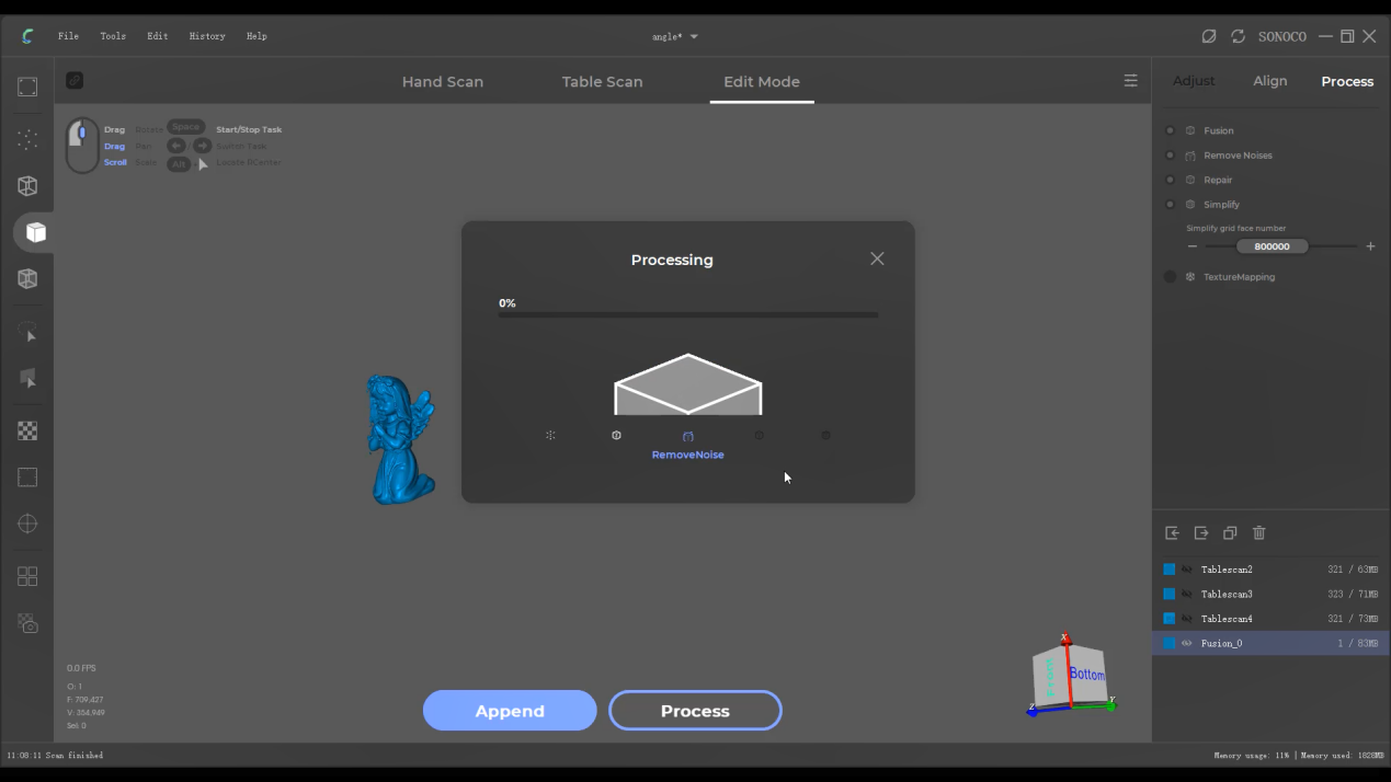
Once the alignment is done, click “process” to go through the automatic data processing. Before that, you can do some configuration about the processing.

1.Fusion: this is the process of data fusion, building the point cloud into the digital terrain model.
2.Remove Noises: automatic removal of noises around the data.
3.Repair: automatic data repair, which is to fill the holes where the area hasn’t been scanned. (Attention: Do not tick this option when scanning some objects with only one surface available, such as human face.)
4.Simplify: simplification of grids, so as to adjust the amount of the grids.
(PS: If there are only a few grids, the details of the model will mostly lose. Our recommendation: the objects of about 1000mm-2 million grid faces, and objects of about 300mm-800,000 grid faces.)
5.TextureMapping: texture mapping is to automatically map the pictures shot by the cameras inside the scanner onto the model.
¶ Click “Apply” to activate automatic processing.
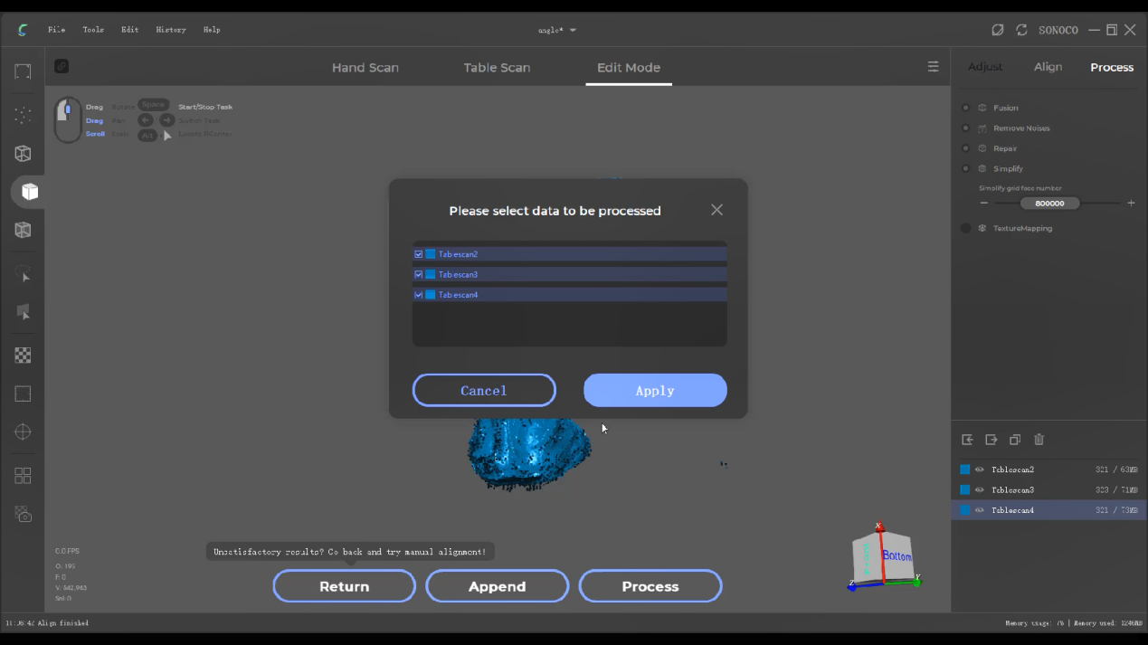
At last, please click “File” in the menu and click “Export” to get your data in the format of OBJ or STL.
¶ In the handheld mode
¶ Step 1: preview
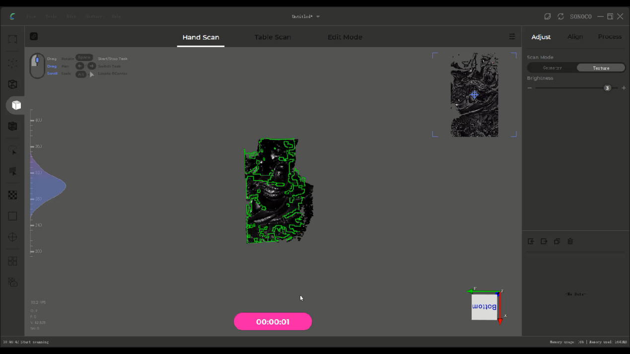
Click “preview” and there will be 10 seconds of countdown. During this period, you can adjust the brightness, the distance between the turntable and the scanner and your scanning angle.
¶ Step 2: scan
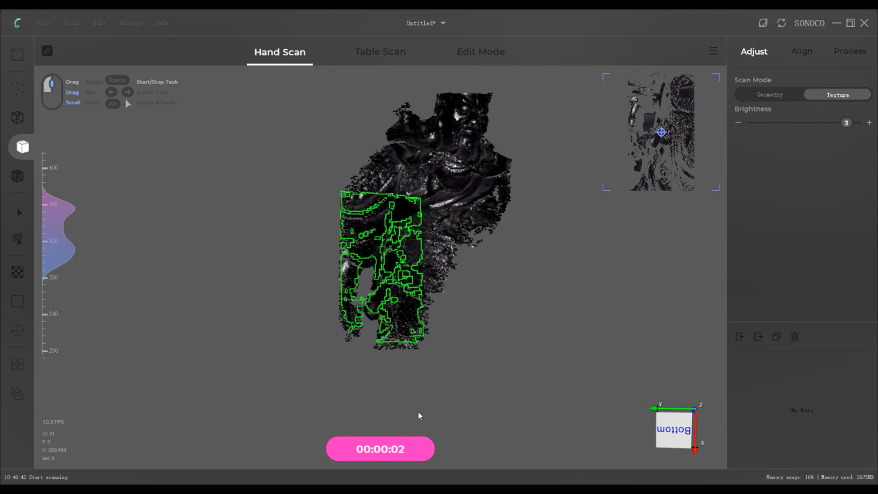
During the scanning process, try to move the scanner in the maximum scanning area. When the tracking is lost, you can retrieve the lost area by scanning the previously scanned area with the function of global relocation.
In the handheld mode, same with the turntable mode, you can also scan your model in different postures to get a descent and complete result.
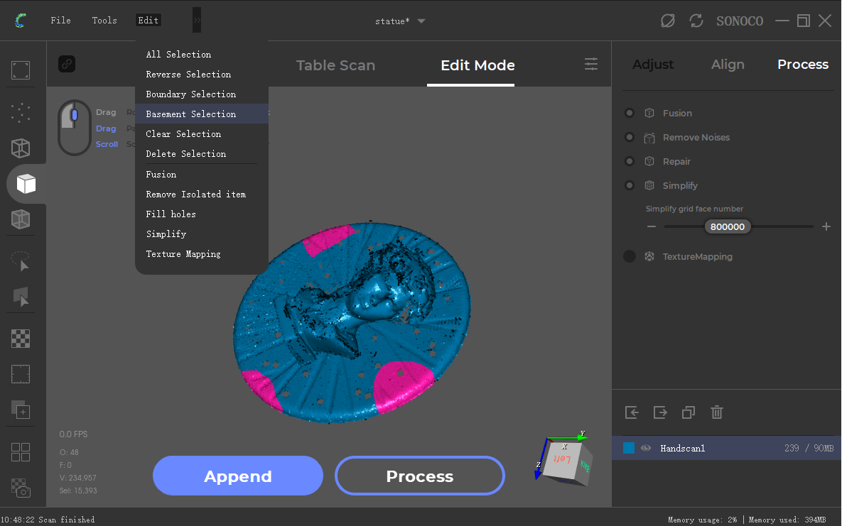
¶ Step 3: remove the basement
First, enter the edit mode.
Second, hold down the Ctrl key and the left mouse button to select 3 areas in the basement.
Then right click your mouse and choose “selection plane” to calculate the whole basement.
Now, the basement will turn red.
¶ Step 4: process
Click “process” , rename your project and save it. Then click “Apply” to activate automatic processing.
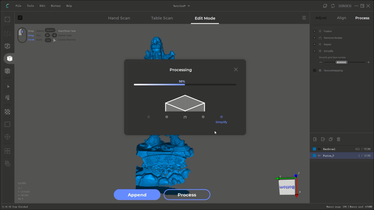
At last, please click “File” in the menu and click “Export” to get your data in the format of OBJ or STL.
¶ Advanced Tutorials
¶ Manual Alignment
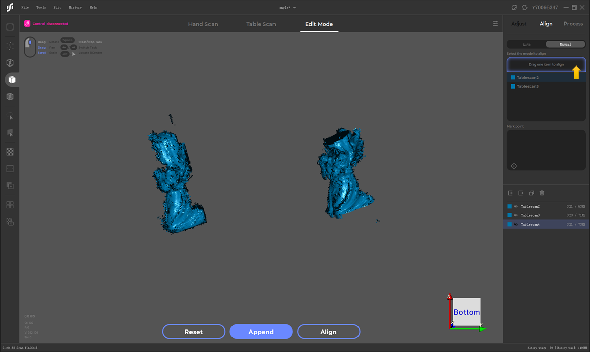
Drag one scan in the area where the arrow in the pic is pointing to, setting it as the reference model.
( In the following picture, we will align Tablescan3 with Tablescan2 and the reference model is Tablescan2.)
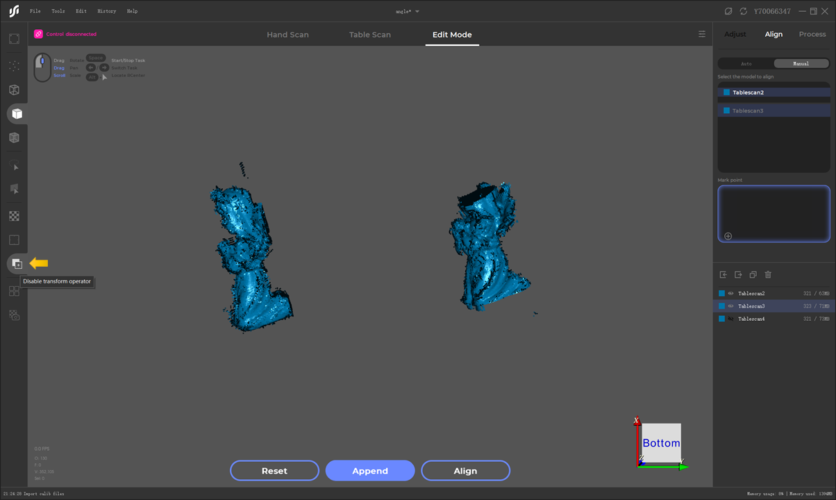
Click the button for separating models that the arrow in the pic is pointing to, hold Alt and the middle mouse button to separate them, and hold Alt and the left mouse button to adjust the posture of the model.
Click the little plus icon down here to add pairs of mark points.
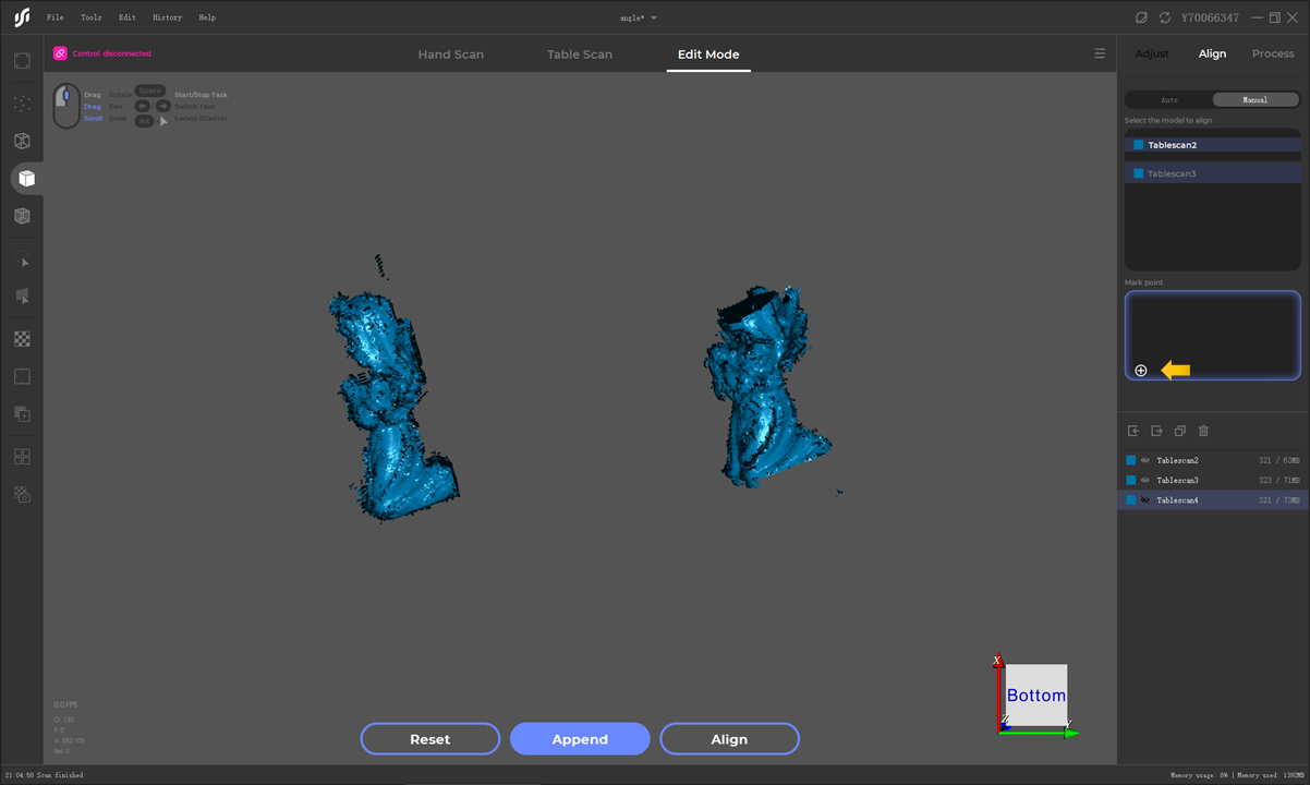
Pick up the pairs in the menu successively and create the corresponding mark points in the two models, as the picture shows:
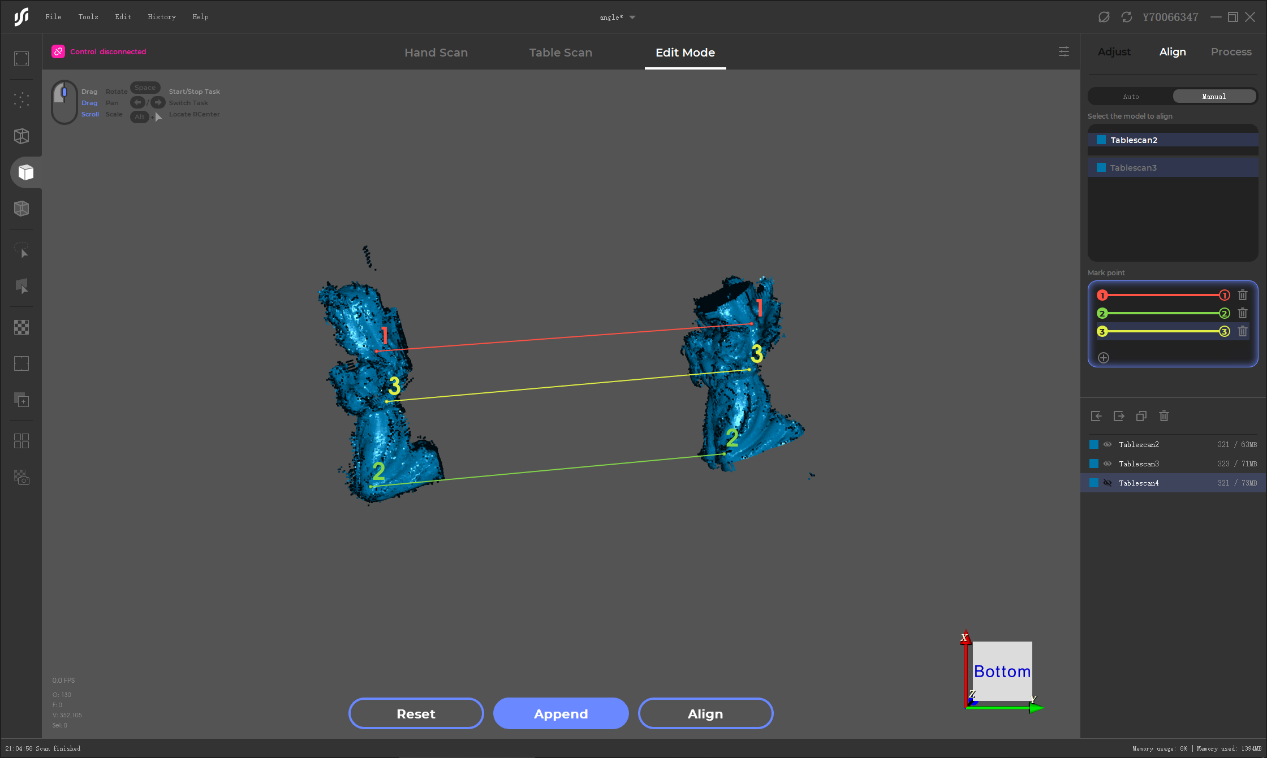
With three pairs of mark points created, click “ Align” and operate the manual alignment.
¶ Advanced TutorialsEditing the model
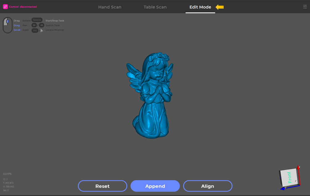
¶ Step 1: enter the editing mode
Switch into the editing mode as the picture shows:
Pick up the scan that needs editing in the data menu as the picture shows:
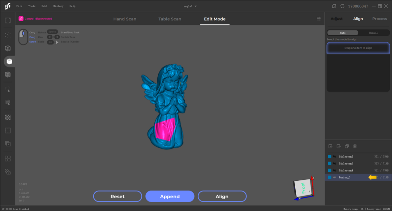
This is the selector for selecting area in the model.

Hold Ctrl and the left mouse button to select.
Click “Delete” on your keyboard to remove unwanted area.

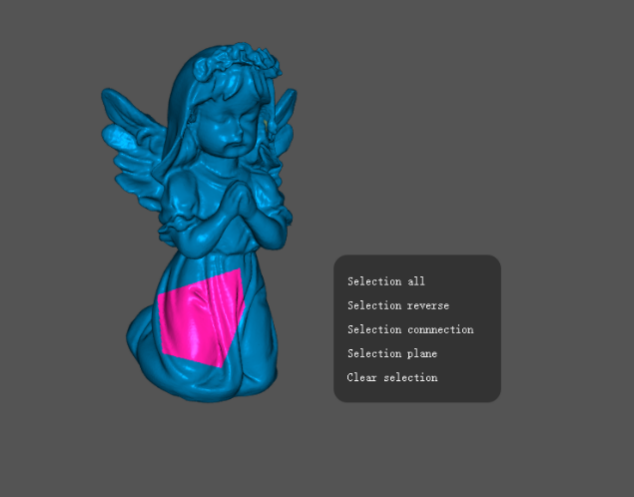
Right click your mouse to show the menu in the following picture:
1.Selection all
2.Selection reverse
3.Selection connection
4.Selection plane
5.Clear selection
