¶ 1.Propeller Scanning:
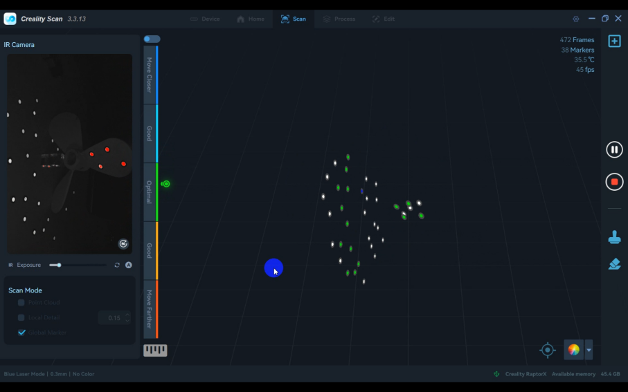
1)Stick 5 to 6 marker points on each of the front and back sides of the propeller.
Stand the propeller blades upright. In the software, select "Global maker" mode to capture all the marker points on the propeller.
Note: You can also paste some marker points on the desktop as auxiliary stitching points.
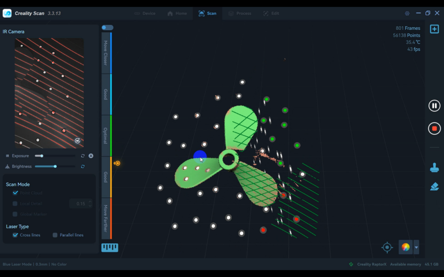
2) Switch to "Point Cloud" Mode and scan the point cloud data for both sides.
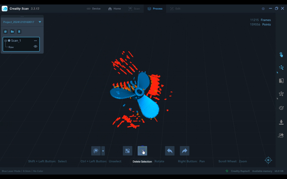
3)Click the "Finish Scan" button to process the point cloud. Delete any unnecessary points.
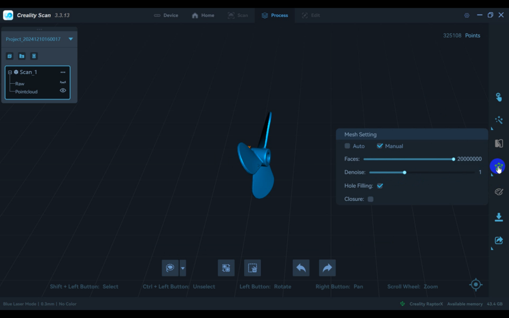
4)In the point cloud "Optimization Settings," adjust the "Resolution" and "Sensitivity," then click the icon to process.
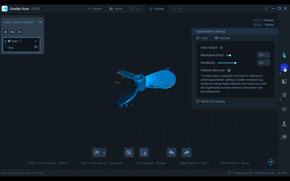
5)Click "Mesh" to mesh the point cloud and complete the scan.
¶ 2. Propeller Reverse Modelling:
¶ (1)Import Data:
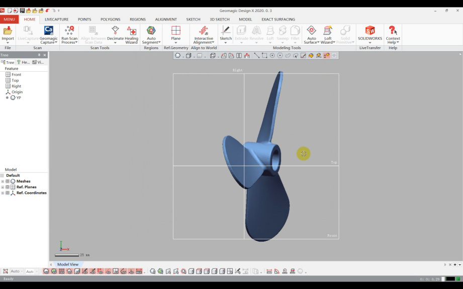
Import the "Propeller Data" into the reverse engineering software Geomagic Design X.
¶ (2)Coordinate Alignment:
1)Create alignment reference features.
2)Enter "Interactive Alignment" and perform a 321 alignment based on the workpiece structure, and complete alignment.

¶ (3)Blade Modeling:
1)Divide one blade surface into a "Regions" in the software
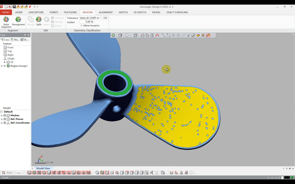
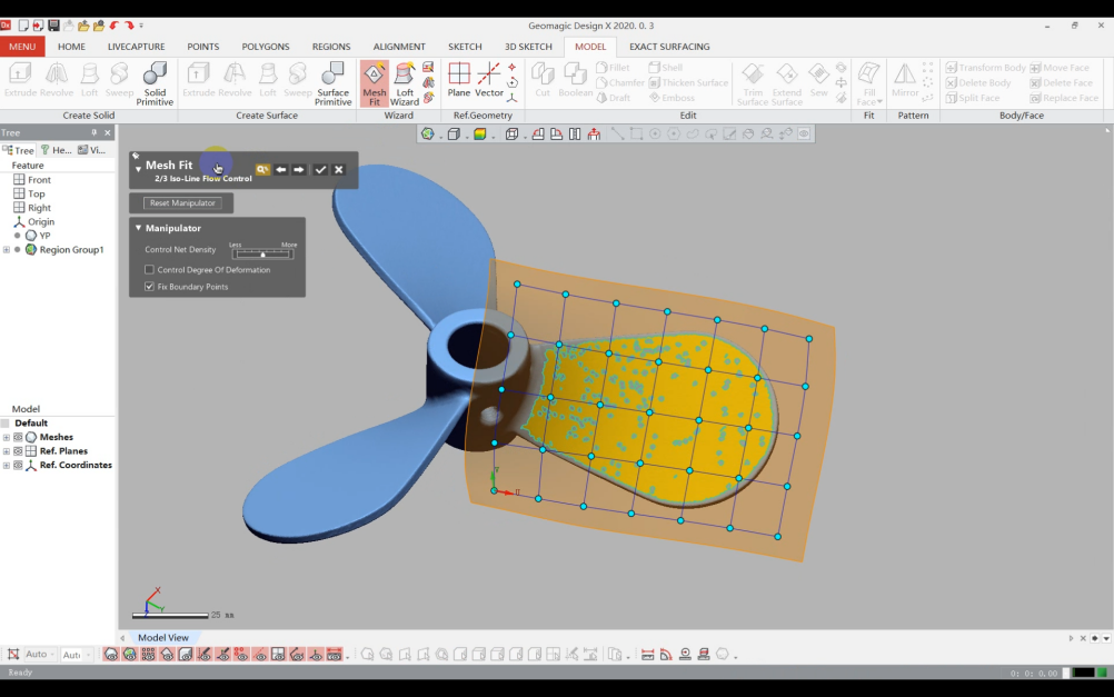
2)Use the "Mesh fit" tool to create the curved surface.
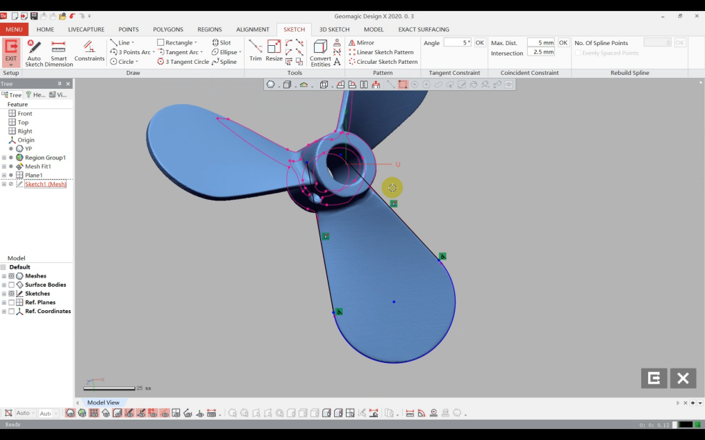
3)Create a sketch plane, enter "Sketch" with this plane, and redraw the blade contour using sketch lines.
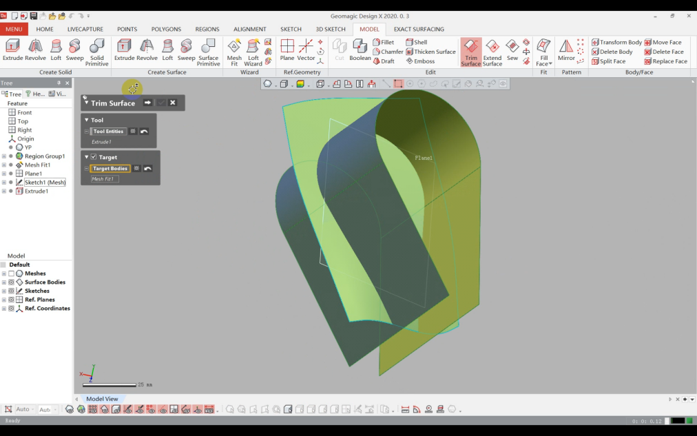
4)Extrude the surface and use it to trim excess areas.
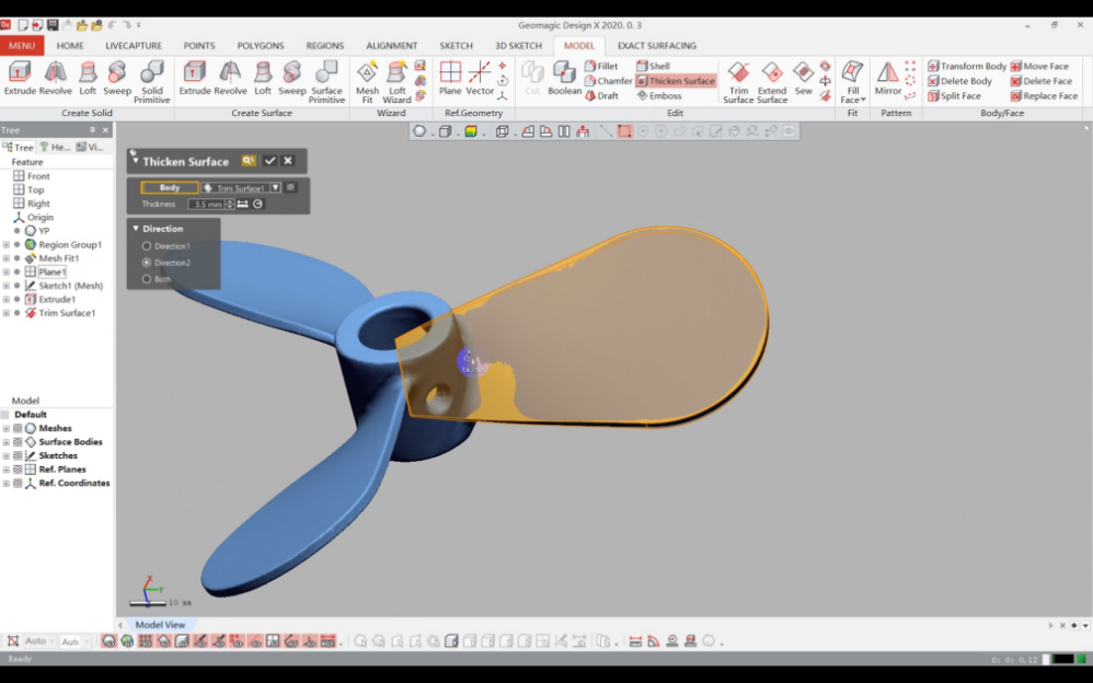
5)Thicken the blade surface based on its actual thickness
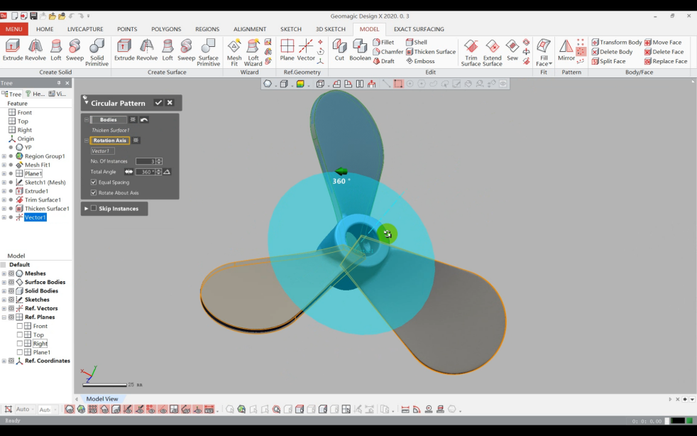
6)Array the blades, complete the solid modeling.
¶ (4)Hub Modeling:
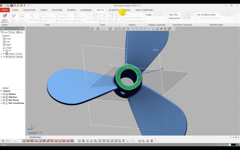
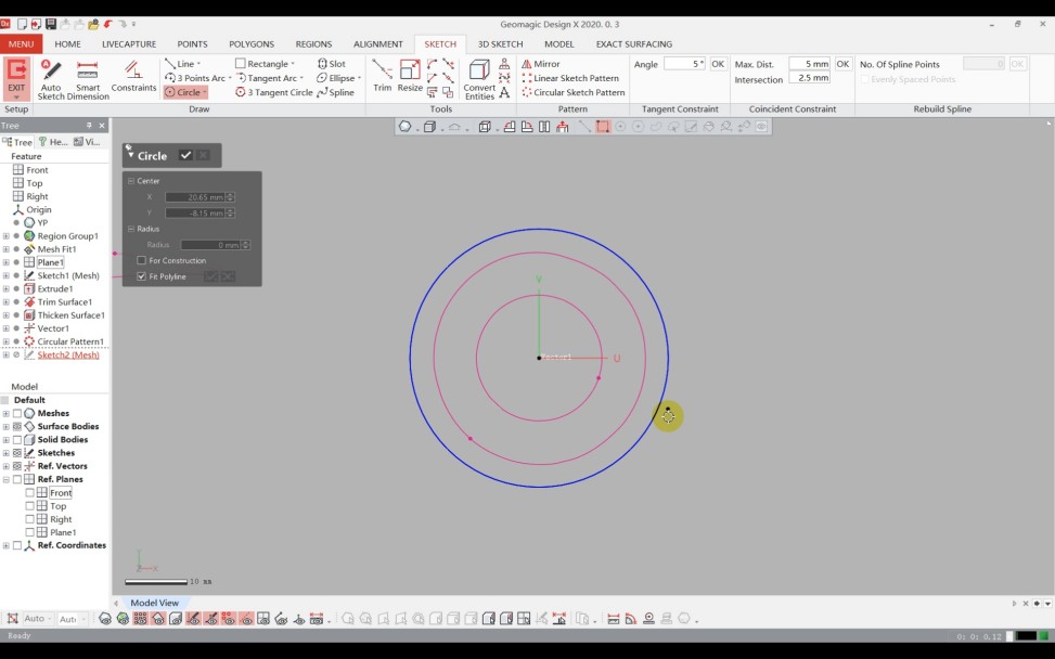
1)Use "Sketch" to draw the hub’s cross-sectional sketch.
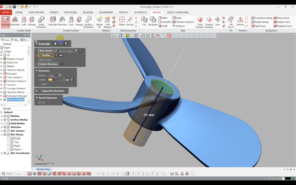
2)Extrude the hub sketch into a solid and merge it with the blades.

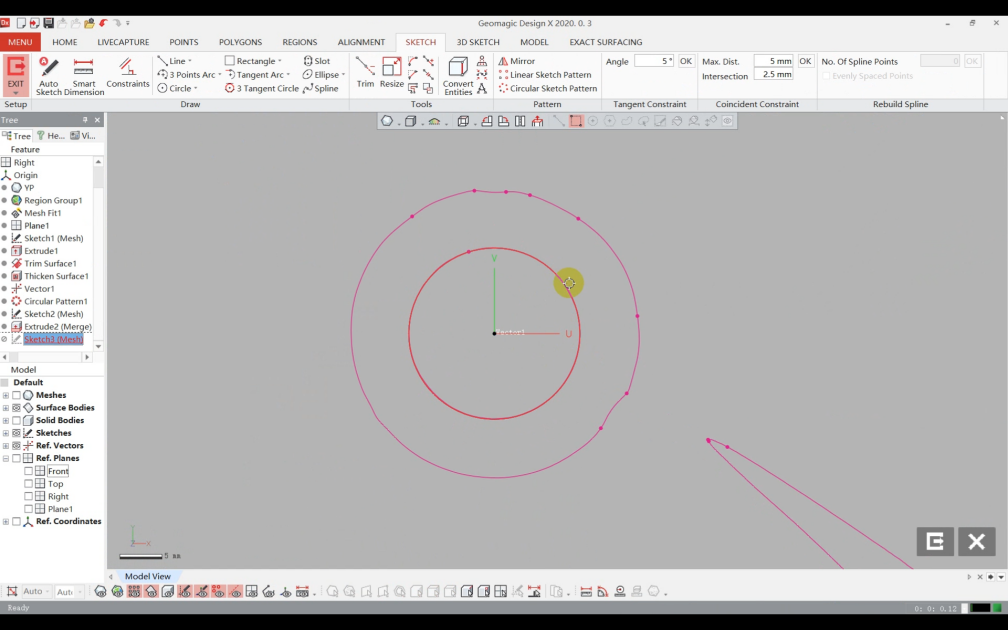
3) Use "Sketch" to draw the hub’s through-hole sketch.
4)Extrude the sketch and cut out the through-hole.
¶ (5)Fillet Edges:
Add fillets to edges as needed.

(6) Reverse Modeling Completed.